cc/td/doc/product/cable/cab_rout
hometocprevnextglossaryfeedbacksearchhelp
PDF

Table Of Contents

Installing a Cisco uBR-MC28U/X
Cable Interface Line Card

Purpose

Feature Description

Prerequisites

Installing the Card

Cabling

Removing the Card

Troubleshooting

Technical Specifications

Related Documentation


Quick Start Guide

Installing a Cisco uBR-MC28U/X
Cable Interface Line Card


Warning Only trained and qualified personnel should be allowed to install, replace, or service this product.


Caution You must be properly grounded before handling this ESD-sensitive product.

1 Purpose

This quick start guide shows you how to install a Cisco uBR-MC28 cable interface line card in the Cisco uBR7246VXR router.

2 Feature Description

The Cisco uBR-MC28 cable interface line card improves RF performance, supports spectrum management, increases system performance and supports online insertion and removal (OIR).
The line card is available in two configurations:

Cisco uBR-MC28U—with an onboard upconverter and green end tabs

Cisco uBR-MC28X—without an onboard upconverter and with yellow end tabs

3 Prerequisites

The Cisco NPE-400 or Cisco NPE-G1 must be used with this card.

If you are replacing a Cisco uBR-MC28C card with a Cisco uBR-MC28U/X card, you must reconfigure the card.


Caution We recommend that you reload a Cisco 7200 series universal broadband router when replacing a cable interface line card with a card of a different type.

4 Installing the Card


Step 1 Make sure that you are grounded.

Step 2 Use both hands to grasp the card by its metal carrier edges and align the card with the slot guides, component side up.

Step 3 With the metal carrier aligned in the slot guides (see Figure 1), gently slide the card into the card slot until you can feel it seat in the backplane connectors.

Step 4 Tighten the captive screws.


Note The captive screws provide grounding for the electromagnetic interference (EMI) shielding.


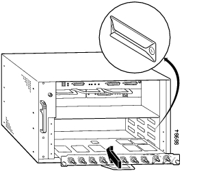
Figure 1 Installing the Card in the Chassis


Cabling


Caution Do not mix upstream ports in domain 0 with upstream ports in domain 1 (see Figure 2).

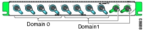
Figure 2 Domain 0 and Domain 1

Cabling the Cisco uBR-MC28U

The Cisco uBR-MC28U cable interface line card has an onboard upconverter. To cable the card:


Step 1 Connect the downstream cables to the downstream ports (DS0-DS1).

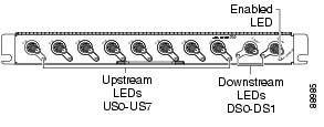
RF downstream port rings and end tabs are green. See Figure 5.

Step 2 Connect the upstream cables to the upstream ports (US0-US7).


Cabling the Cisco uBR-MC28X

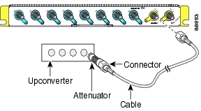
The Cisco uBR-MC28X cable interface line card does not have an onboard upconverter. The card may require up to 10-dB of attenuation due to a higher IF output power (higher then legacy Cisco line cards). To cable the card:


Step 1 Connect the downstream cables to the downstream ports on the card (DS0-DS1).

IF downstream port rings and end tabs are yellow. See Figure 3.

Step 2 Add RF attenuators as required to get the correct IF output. Insert the attenuator between the downstream IF output cable and the upconverter. See Figure 3.

Step 3 Connect the upstream cables to the upstream ports on the card (US0-US7).

Figure 3 Inserting an Attenuator


Note All upstream ports are light blue.


5 Removing the Card

To prevent the alarms from activating, administratively shut down the card before removing it from the chassis. Refer to "Shutting Down and Restarting the Interface" in the Cisco uBR7200 Series Universal Broadband Router Software Configuration Guide.


Step 1 Make sure that you are properly grounded.

Step 2 Disconnect all the cables from the cable interface line card.

Step 3 Unscrew the captive installation screws on the faceplate.

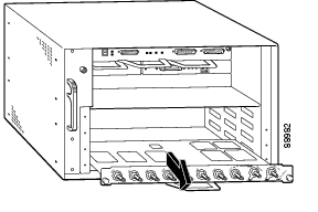
Figure 4 Removing the Card from the Chassis

Step 4 Grasp the handle and carefully pull the card out of its slot (see Figure 4).


Caution Always handle the cable interface line card by the carrier edges and handle; never touch the cable interface line card's components or connector pins.

Step 5 Place the card on an antistatic surface with its components facing upward.


Note If the card is being returned to the factory, immediately place it in a static shielding bag and proper packaging for protection.


Caution For proper cooling and airflow, always install a line card cover in an empty line card slot.


6 Troubleshooting

1. Make sure that the card is securely seated in the chassis.

If the captive screws do not tighten all the way, the card is not properly seated in the chassis or backplane. Carefully pull the card halfway out of the slot, reinsert it, and tighten the captive installation screws.


Caution A partially seated line card can cause the router to reboot.

2. Are all enabled LEDs on?

If yes, the system is operational.

If no, check the following possibilities:

a. Verify that the card has been enabled and configured for operations. The enabled LED remains off when a card has not been configured and enabled.

b. If a port is enabled but its corresponding enabled LED is still off, check to see if the card has pulled away from the router. Reseat the card in its slot. (You do not have to turn off the system power to do this.} After the system reinitializes the interfaces, the enabled LED on the card should come on.

3. If the enabled LED remains off after the above checks, it is likely that the system has detected a processor hardware failure.

Contact Cisco TAC for further information and help. To access the Cisco TAC web site, go to http://www.cisco.com/tac

Figure 5 LEDs

Table 1 LEDs/Status 

LED/Status
Description

ENABLED—green
ENABLED—off

Card operating normally
Card not enabled

US—green
US—off

Upstream enabled
Upstream not enabled

DS—green
DS—off

Downstream enabled
Downstream not enabled


7 Technical Specifications

Table 2 Technical Specifications 

Description
Order Num/ Specifications

Cisco uBR-MC28U,
with upconverter

Cisco uBR-MC28X,
without upconverter

UBR-MC28U, UBR-MC28U=

UBR-MC28X, UBR-MC28X=

Blank covers

UBR-MC-COVER=

Weight—MC28U
Weight—MC28X

6 lbs (2.72 kg)
4.75 lbs (2.15) kg)

Power consumption

MC28U
MC28X

80 Watts (273 BTU/h)
50 Watts (170.6 BTU/h)

Output—MC28U
Output—MC28X

+50 to 61 dBmV at RF
+42 dBmV at IF (+/-2 dB)

Modulation

Upstream (US0-US7)

QPSK
8-, 16-, 32-, 64-QAM

Downstream (DS0-DS1)

64-QAM, 256-QAM

RF output power range—50 to 61 dBmV

Frequency range

Upstream
Downstream

5-65 MHz
70-860 MHz

The Cisco uBR-MC28U/X line card is compatible with most cable systems worldwide, including but not limited to—Asia Pacific, Europe, and the Americas. See Cisco IOS release notes for more information.


8 Related Documentation

For more information, refer to the following:

Cisco uBR7200 Universal Broadband Series Hardware Installation Guide

Cisco uBR7200 Series Cable Interface Line Card Hardware Installation Guide

For other documentation about the Cisco uBR7200 series universal broadband routers, go to the following URL:

http://www.cisco.com/en/US/products/hw/cable/ps2217/tsd_products_support_series_home.html

For information about the 1-year warranty, enter 78-10747-01C0 at the following URL:

http://www.cisco.com/univercd/cc/td/doc/es_inpck/cetrans.htm


hometocprevnextglossaryfeedbacksearchhelp

Posted: Fri Jun 22 13:40:56 PDT 2007
All contents are Copyright © 1992--2007 Cisco Systems, Inc. All rights reserved.
Important Notices and Privacy Statement.