|
|

Product Number: L1010-PWR-1=
This document contains instructions for installing and configuring the LightStream 1010 ATM switch power supply. For complete hardware configuration and maintenance procedures, refer to the LightStream 1010 ATM Switch User Guide publication.
Cisco documentation and additional literature are available on a CD called Cisco Connection Documentation, Enterprise Series. The CD is updated and shipped monthly, so it might be more up-to-date than the printed documentation. To order the Cisco Connection Documentation, Enterprise Series CD, contact your local sales representative or call Customer Service. The CD is available both as a single CD and as an annual subscription. You can access Cisco technical documentation on the World Wide Web Universal Resources Locator (URL) http://www.cisco.com.
Sections in this document include the following:
 | Warning Only trained and qualified personnel should install or replace the LightStream 1010 ATM switch, chassis, power supplies, fan assembly, or modules. |
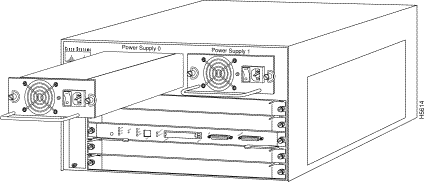
The LightStream 1010 uses a five-slot, modular chassis featuring the option of dual, fault-tolerant, load-sharing power supplies. (See Figure 1.) The central slot in the LightStream 1010 is dedicated to a single, field-replaceable ATM switch processor (ASP) module that supports both the 5-Gbps shared memory and the fully nonblocking switch fabric. The ASP also supports the feature card and high performance reduced instruction set (RISC) processor that provides the central intelligence for the device. The remaining slots support up to four hot-swappable Carrier Modules (CAMs). Each CAM supports up to two hot-swappable Port Adapter Modules (PAMs) for a maximum of eight PAMs per switch, supporting a wide variety of desktop, backbone, and wide-area interfaces.
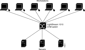
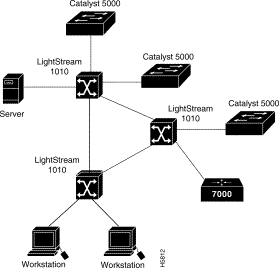
The LightStream 1010 ATM switch provides switched ATM connections to individual workstations, servers, LAN segments, or other ATM switches and routers using fiber-optic, unshielded twisted-pair (UTP), and coaxial cable.
Figure 2 shows an example of a network configuration using the LightStream 1010 ATM switch in a high-performance workgroup.

Figure 3 shows an example of a network configuration using the LightStream 1010 ATM switch for a campus backbone.

The LightStream 1010 ATM switch comes equipped with one 350W, AC-input power supply. An identical, optional, second power supply is also available for fault-tolerant power. Dual power supplies are automatically load-sharing and redundant, which means that a second power supply can be installed or replaced without interrupting system operation.
When two power supplies are installed and both are turned on, each concurrently provides about half of the required power to the system. If one of the power supplies fails, the second power supply immediately ramps up to full power to maintain uninterrupted system operation. Load-sharing and fault-tolerance are automatically enabled when the second power supply is installed; no software configuration is required.
Each power supply can be connected to a separate AC source so that, in case of an input power line or power supply failure, the second power supply maintains uninterrupted system power.
Table 1 lists the LightStream 1010 ATM switch and power supply specifications:
| Description | Specifications |
|---|---|
Dimensions (H x W x D) | 10.4 x 17.25 x 18.4" (26.4 x 43.1 x 46.0 cm) |
Weight | 9.55 lb (4.40 kg) |
Operating temperature | 32 to 104° F (0 to 40° C) |
Nonoperating temperature | -40 to 167° F (-40 to 75° C) |
Humidity | 10 to 90%, noncondensing |
Altitude | -500 to 10,000 ft (-52 to 3,048 m) |
Microprocessor | 100-MHz MIPs R4600 |
Connections | 32,000 point-to-point, 2,048 multi-to-multipoint |
Mean Time Between Failures | 2.6 years for system configuration |
Agency approvals | Safety: UL4 1950, CSA5-C22.2 No. 950-93, and EN60950 |
The eight available PAMs support any combination of network interfaces to provide the following maximum port densities:
You can install any combination of PAMs in any of the eight available PAM slots. There are no restrictions on either the number of modules that can be installed or their proximity to the ASP.
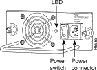
Each power supply has one LED. The LED is green when the power supply is powered on and operating within tolerances. The LED is off when the power supply is powered off, the power cord is disconnected, or if the power supply has malfunctioned.
See the section "ASP LEDs" for a description of the PS0 and PS1 LEDs on the ASP.
The LEDs on the ASP indicate the status of the system, which includes the fan assembly and power supply(ies) and the ASP. The ASP LEDs are shown in Figure 4 and described in Table 2.

| LED | Description |
|---|---|
Status | The switch performs a series of self-tests and diagnostic tests. |
Fan | Indicates whether or not the fan is operational. |
PS 0, left bay | If the power supply is operational, the PS0 LED is green. |
PS 1, right bay | If the power supply is operational, the PS1 LED is green. |
Link | Green---The Ethernet port is operational. |
RX (Receive) | Off---No signal received. |
TX (Transmit) | Off---Not transmitting. |
The power supplies are self-monitoring. Each power supply monitors its own temperature and internal voltages.
The environmental monitoring and reporting functions enable you to maintain normal system operation by identifying and resolving adverse conditions before the system fails. Environmental monitoring functions constantly monitor the internal chassis air temperature. Each power supply monitors its own voltage and shuts itself down if it detects a critical condition within the power supply. The reporting functions enable you to retrieve and display the present values of measured parameters, and the reporting functions display alarms on the console if any of the monitored parameters exceed defined thresholds.
The environmental monitoring functions use three levels of status conditions to monitor the system: normal, alarm, and critical. The processor monitors the temperature inside the module compartment, and the power supplies use the normal and critical levels to monitor DC voltages. Table 3 lists temperature thresholds for the processor-monitored levels. Table 4 lists the DC power thresholds for the normal and critical power-supply-monitored levels.
| Parameter | Normal | Alarm |
|---|---|---|
Airflow | 10 to 55° C | > 55° C |
| Parameter | Critical | Normal | Critical |
|---|---|---|---|
+5V | < 4.74V | 4.74-5.26V | > 5.26V |
The three levels of status condition includes:
The power supply monitors its own internal temperature and voltages. The power supply is either within tolerance (normal) or out of tolerance (alarm level), as shown in Table 4. If an internal-power-supply temperature or voltage reaches a critical level, the power supply shuts down without any interaction with the processor.
When preparing your site for network connections to the switch, you need to consider a number of factors related to each type of interface:
The length of your networks and the distances between connections depend on the type of signal, the signal speed, and the transmission media (the type of cabling used to transmit the signals). For example, fiber-optic cable has a greater channel capacity than twisted-pair cabling. The following distance limits are provided as guidelines for planning your network connections before installation.
The following publications contain information on determining attenuation and power budget:
The following guidelines help ensure your safety and protect the equipment. This list is not inclusive of all potentially hazardous situations that you may be exposed to as you install the module, so be alert.
 | Warning Metal objects heat up when connected to power and ground, and can cause serious burns. |
The supervisor engine, modules, and redundant (second) power supplies are designed to be removed and replaced while the system is operating without presenting an electrical hazard or damage to the system. Before removing a redundant power supply, ensure that the first supply is powered on. However, you must shut down the system before removing or replacing any of the replaceable components inside the front panel, for example, the backplane. Never install equipment that appears damaged.
Follow these basic guidelines when working with any electrical equipment:
In addition, use the guidelines that follow when working with any equipment that is disconnected from a power source but still connected to telephone wiring or other network cabling.
 | Warning Do not work on the system or connect or disconnect cables during periods of lightning activity. |
The switch is configured to your order and is ready for installation and startup when it leaves the factory. As your communication requirements change, you may want to upgrade your system and add or replace a power supply. This section describes the procedures for installing, replacing, and reconfiguring power supplies.
The 376W power supplies (AC-input) are used in the switch support redundant hot swapping. When two power supplies are installed, you can remove or replace one of the supplies without affecting system operation. When power is removed from one supply, the redundant power feature causes the second supply to ramp up to full power and maintain uninterrupted system operation. In systems with dual power supplies, connect each power supply to separate input lines so that, in case of a line failure, the second source is still available and can maintain maximum overcurrent protection for each power connection.
A modular power cord connects each power supply to the separate site power sources.
 | Caution Use both hands to remove and install power supplies. |
 | Caution Keep hands and fingers out of the power-supply bays. High voltage is present on the power backplane when the system is operating. |
You need a 1/4-inch flat-blade screwdriver to remove and install filler plates and to loosen or tighten the captive installation screws on the power supply.
Always install a filler plate over an empty power supply bay to protect the connectors from contamination.
Take the following steps to remove a power supply:
Step 1 Turn OFF the power switch on the power supply you are removing. (See Figure 5.)
 | Caution Failure to turn off the power supply could result in equipment damage. |

Step 2 Disconnect the power cord from the power source.
Step 3 Remove the power cord from the power inlet.
Step 4 Use a screwdriver to loosen and remove the captive installation screws on the sides of the supply. (See Figure 6.)

Step 5 Grasp the power-supply handle with one hand and place your other hand underneath to support the bottom of the supply, as shown in Figure 7.

Step 6 Pull the supply out of the bay and put it aside.
Step 7 If the power-supply bay is to remain empty, install a blank power-supply filler plate (part number 700-00177-01) over the opening and secure it with the mounting screws. This precaution protects the inner chassis from dust, as well as the connectors in the rear of the bay, which expose current levels when the chassis is powered on.
Step 8 Replace the power supply by following Step 1 through Step 5 in reverse.
 | Caution Keep hands and fingers out of the power-supply bays. High voltage is present on the power backplane when the system is operating. |


|
|