|
|

This chapter tells you how to determine the status of LightStream 2020 (LS2020) enterprise ATM switches and their components. It shows command examples and explains how you can obtain additional information.
This chapter also provides the monitoring procedures for the CLI, the LS2020 monitor and the LS2020 topology map. The monitor displays a graphical representation of an LS2020 switch, its cards and ports, and the topology map displays a graphical representation of the LS2020 network.
Two tools are available for monitoring the LS2020: the LS2020 monitor program and the CLI. In the monitor program, you click on components to display information about them. In the CLI, you use the show command to monitor a switch or its components. When you issue a show command, the switch retrieves the requested information from the MIB. You may see a collection of MIB attributes displayed or you may see only a single attribute. You can monitor the following LS2020 components and subsystems:
CLI procedures to monitor all of these components and subsystems, except traps, are described next. See the LightStream 2020 Traps Reference Manual for descriptions on trap monitoring.
This section provides the steps for monitoring the hardware components of an LS2020 switch:
To monitor the chassis, follow these steps. The information that displays applies to the LS2020 switch.
Step 1 Verify that the target switch is correct by entering the following at the cli> prompt:
cli> show snmp
If you need instructions on changing the target switch, see the section on "Setting the Target Switch for CLI Commands" in the chapter entitled "The Command Line Interface."
Step 2 Enter the following at the cli> prompt:
cli> show chassis <parameter>
where
<parameter>= all (default)
general
agent
congestion
primaryswitch
powersupply
card
listff
listdlci
listvci
listtrunk
listpvc
Figure 4-1 and Figure 4-2 show what information displays when you enter show chassis all.
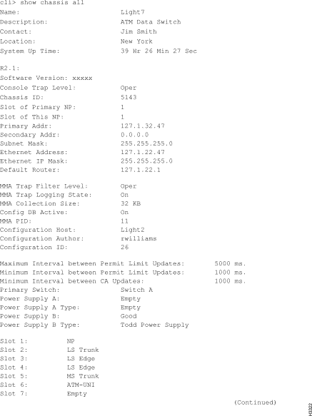
If you enter any parameter except all, a subset of the previous screen shown displays. For example, if you enter the command show chassis agent, information similar to the following is displayed:
cli> show chassis agent
MMA Trap filter Level:            Oper
MMA Trap Logging State:           On
MMA Collection Size:              32 KB
Config DB Active:                 On
MMA PID:                          11
Configuration Host:               boston
Configuration Author:             Bob Williams
Configuration ID:                 26
cli>
You can monitor network processor (NP) cards, edge cards, trunk cards, and switch cards. You select the card you want to monitor by specifying its card number (slot number).To determine a card's slot number, you can look at the front of the system to see the numbered slots as shown in Figure 4-19. When you specify a card, you also get information on its associated access card. To monitor the cards in the LS2020 switch, follow these steps.
Step 1 Verify that the target switch is correct by entering the following at the cli> prompt:
show snmp
If you need instructions on changing the target switch, see the section on "Setting the Target Switch for CLI Commands" in the chapter entitled "The Command Line Interface."
Step 2 Enter the following at the cli> prompt:
show card <card #> <parameter>
where
<card #> = The slot in which the card you want to monitor is located.
1 - 2 for NP cards
2 - 10 for line cards
switcha or switchb for switch cards
<parameter>= all (default)
name (no information available for switch cards)
processid
status
version
peak-cell-rate
hardware
ports (no information available for NP or switch cards)
The results of this command will vary, depending on the type of card in the slot. If you enter any parameter except the all parameter, a subset of the attributes displays.
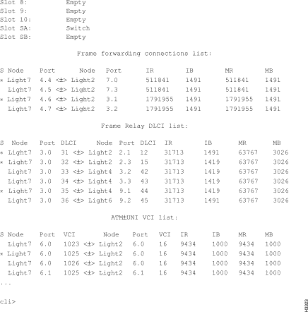
When you enter show card 5 all, information similar to the following (for a low-speed edge card) is displayed as shown in Figure 4-3:
The csumon tool, available from the bash shell, lets you monitor the DSU/CSU for the following:
In addition, you can use csumon to issue commands to an external DSU/CSU attached to a low-speed interface.
You can obtain CSU statistics by connecting to an external data service unit/channel service unit (DSU/CSU) from an LS2020 switch through a serial line. This provides a terminal to the DSU/CSU. You use its own interface to set up and monitor the DSU/CSU. (See the documentation for the DSU/CSU for details.)
Step 1 Connect the LS2020 switch to the external DSU/CSU by connecting an EIA/TIA-232 serial cable from the control port on the fantail to the CSU craft (or console) port.
Step 2 To access the bash prompt, log in as root or fldsup on the LS2020 switch to which the DSU/CSU you want to monitor is attached.
Step 3 Test the connection by using the following command:
csumon <.card.port#>
where
<.card.port#> = The target switch card and port number in the LS2020 switch, entered in .card.port format (card 2 - 10; port 0 - 7)
Figure 4-4 shows a screen displaying the kind of information you might see in a DSU/CSU status display. The display you see may vary, depending on the DSU/CSU you are using.
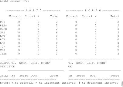
While the statistics are displayed, you can enter the following input to refresh the screen or alter the counter display.
| Input | Action |
| ? | Refresh screen |
| + | Display the next interval counters |
| - | Display the previous interval counters |
Step 5 Terminate the display by pressing ^C. This returns you to the bash prompt.
Step 6 To learn about commands you can issue to the DSU/CSU, consult its documentation. To obtain help on csumon, enter the following command at the bash prompt:
csumon
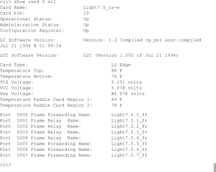
The medium-speed line card (MSC) has a built-in DSU/CSU. Use the following steps to monitor and display the DS3 MIB statistics for MSC ports. MSC CSU statistics are available using the standard DS3 MIB variables.
Step 1 To access the bash prompt, log in as root or fldsup to the LS2020 switch.
Step 2 Enter the following at the bash prompt:
csumon <.card.port#>
where
<.card.port#> = The target switch card and port number in the LS2020 switch, entered in .card.port format (card 2 - 10; port 0 - 7).
A screen similar to the one in Figure 4-5 is displayed. Although you enter only one port number, information for both ports on the MSC displays.
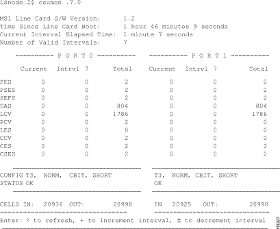
The DS3 MIB maintains these counters over a 24-hour period in 15-minute intervals. The Total column in the display includes up to 96 complete intervals. The Current column includes all counts that will make up the next complete interval. The Intrvl column shows the selected complete interval (from 1 to 96), depending on the actual number of complete intervals. The values that change are updated once per second.
Table 4-1 lists the counters and their definitions.
| Counter1 | Definition |
| PES | P-bit Errored Seconds |
| PSES | P-bit Severely Errored Seconds |
| SEFS | Severely Errored Framing Seconds |
| UAS | UnAvailable Seconds |
| LCV | Line Coding Violations |
| PCV | P-bit Coding Violations |
| LES | Line Error Seconds |
| CCV | C-bit Coding Violations |
| CES | C-bit Errored Seconds |
| CSES | C1-bit Severely Errored Seconds |
| Status Term | Definition |
| OK | No alarms present |
| RED | Loss of Framing |
| YELLOW | Far End Receive Failure |
| BLUE | Receiving an Alarm Indication Signal |
| |
While the statistics are displayed, you can enter the input shown below to refresh the screen or alter the counter display.
| Input | Action |
| ? | Refresh screen |
| + | Display the next interval counters |
| - | Display the previous interval counters |
Step 4 Terminate the display by pressing ^C. This returns you to the bash prompt.
Step 5 To obtain help on csumon, enter the following command at the bash prompt:
csumon
These steps allows you to monitor the ports on a particular card. You can look at information for a single port, a collection of ports, or a range of ports.
Step 1 Verify that the target switch is correct by entering the following at the cli> prompt:
show snmp
If you need instructions on changing the target switch, see "Setting the Target Switch for CLI Commands" in the chapter entitled "The Command Line Interface."
Step 2 Enter the following at the cli> prompt:
show port <port#> <parameter1> <parameter2>
where
<port#> = The number of the port for which information displays. The port number is in card.port format (card = 2 - 10; port = 0 - 7).
<parameter> = all (default)
name
status
statistics
physical
frameforward
framerelay
listdlci
listpvc
listvci
dlci
vci
vpi
fddi
datarate
wgrp
bflt
ipflt
ipxflt
np-deliver
sonet
stb
bflt-def
ipflt-def
ipxflt-def
bcast-limit
An example for each of the port types is shown in this section. Figure 4-6 is an example of the display you see when you enter show port 5.0 all for an MS trunk port.
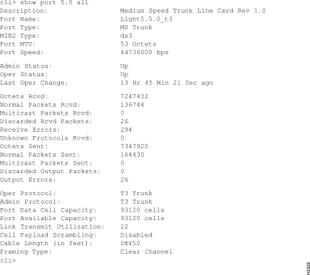
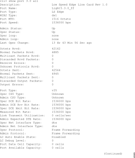
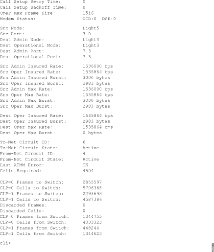
Figure 4-7 and Figure 4-8 are examples of the display you see when you enter show port 3.0 all for a frame forwarding port.
To monitor the modem port on the switch card's console/modem assembly, follow these steps:
Step 1 Verify that the target switch is correct by entering the following at the cli> prompt:
show snmp
If you need instructions on changing the target switch, see "Setting the Target Switch for CLI Commands" in the chapter entitled "The Command Line Interface."
Step 2 Enter the following at the cli> prompt:
show modem <slot #> <parameter>
where
<slot #> = sa or sb for the switch cards
<parameter> = all
initstring
The following is an example of the display you see when you enter show modem sa all:
show modem sa all
These steps tell you how to monitor the status of your redundant components (switch cards, NPs, and power supplies).
Step 1 Verify that the target switch is correct by entering the following at the cli> prompt:
show snmp
If you need instructions on changing the target switch, see "Setting the Target Switch for CLI Commands" in the chapter entitled "The Command Line Interface."
Step 2 To look at the status of switch cards, enter the following at the cli> prompt:
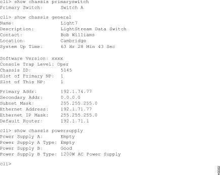
show chassis primaryswitch
This command indicates which switch card is the active switch card. If you have a second switch card, you can assume it is the backup switch card.
Step 3 To look at the slot associated with each of the NPs, enter the following at the cli> prompt:
show chassis general
This command displays a number of details including the slot for the active NP, the slot of this NP, and the system up time. The system up time indicates how long this NP has been up.
Step 4 To look at the status of power supplies, enter the following at the cli> prompt:
show chassis powersupply
This command displays the status and type of the two power supplies, A and B.
Figure 4-9 shows the output for the three commands previously described.
This section provides steps to monitor configuration and status of the following connections and processes of an LS2020 switch:
To monitor the ATM UNI virtual channel identifiers (VCIs) configured on a particular ATM UNI port, follow these steps. They provide you with information on the individual connections configured on each port. This information is available for ATM UNI ports only.
Step 1 Verify that the target switch is correct by entering the following at the cli> prompt:
show snmp
If you need instructions on changing the target switch, see "Setting the Target Switch for CLI Commands" in the chapter entitled "The Command Line Interface." To get a list of all VCIs configured on a particular ATM UNI port, enter the following at the cli> prompt:
show port <port#> listvci
where
<port#> = The number of the port for which information displays. The port number is in card.port format (card = 2 - 10; port =0 - 7).
Step 2 Once you have a list of all ATM-UNI VCIs, you can look at a particular VCI by entering the following at the cli> prompt:
show port <port#> vci <vci#>
where
<vci#> = The number of the VCI for which information displays.
Figure 4-10 is an example of the display you see when you enter show port 6.0 vci 16.
You can also get a list of all the ATM UNI VCIs for the entire chassis by entering the show chassis listvci command.
These steps allow you to monitor individual data link connections configured on frame relay ports. These connections are recognized by their data link connection identifiers (DLCIs).
Step 1 Verify that the target switch is correct by entering the following at the cli> prompt:
show snmp
If you need instructions on changing the target switch, see "Setting the Target Switch for CLI Commands" in the chapter entitled "The Command Line Interface." To get a list of all data link connections configured on a particular frame relay port, enter the following at the cli> prompt:
show port <port#> listdlci
where
<port#> = The number of the port for which information displays. The port number is in card.port format (card = 2 - 10; port = 0 - 7).
Step 2 Once you have a list of DLCIs, you can look at a particular circuit by entering the following at the cli> prompt:
show port <port#> dlci <dlci#>
where
<dlci#> = The DLCI number for which information displays. The DLCI number must be between 16 and 991.
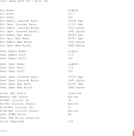
Figure 4-11 is an example of the display you see when you enter show port 10.7 dlci 141.
You can also get a list of all the frame relay connections for the entire chassis by entering the show chassis listdlci command.
These steps let you monitor the attribute settings for the CLI program itself.
Step 1 Enter the following at the cli> prompt:
show cli <parameter>
where
<parameter> = all (default)
echosource
lineedit
log
term
time
timer
timestamp
timeout
traplevel
debug
banner
The following is an example of the display you see when you enter show cli.
cli> show cli
The collector lets you run up to 25 collections at one time. You can set up the collections to save user-defined data for a specified time interval and you can use this data for future analysis. For further information on creating collections, see the "Statistics and Data Collection" chapter.
To monitor the status of a particular collection, follow these steps:
Step 1 Verify that the target switch is correct by entering the following at the cli> prompt:
show snmp
If you need instructions on changing the target switch, see "Setting the Target Switch for CLI Commands" in the chapter entitled "The Command Line Interface." To look at the status of a particular collection, enter the following at the cli> prompt:
show collection [<collection #>]
where
[<collection #>] = The number of any collection that has been defined. If you do not enter a collection number, CLI displays all collections that have been defined.
The following is an example of the display you see when you enter show collection 1.
show collection 1
To monitor the status of the global information distribution (GID) software, follow these steps.
Step 1 Verify that the target switch is correct by entering the following at the cli> prompt:
show snmp
If you need instructions on changing the target switch, see the section on "Setting the Target Switch for CLI Commands" in the chapter entitled "The Command Line Interface."
Step 2 Enter the following at the cli> prompt:
show gid <parameter>
where
<parameter> = all (default)
general
synchronization
cards
clients
neighbors
ports
ip
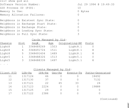
Figure 4-12 is an example of the display you see when you enter show gid all.
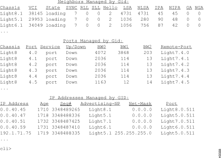
If you enter any parameter except all, a subset of the attributes is displayed.
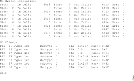
These steps let you monitor the status of the neighborhood discovery (ND) software. This information can tell you what hardware configuration the running software is using or the neighbors of the switch.
Step 1 Verify that the target switch is correct by entering the following at the cli> prompt:
show snmp
If you need instructions on changing the target switch, see the section on "Setting the Target Switch for CLI Commands" in the chapter entitled "The Command Line Interface."
Step 2 Enter the following at the cli> prompt:
show nd <parameter>
where
<parameter> = all (default)
general
ndcards
neighbors
switchupdown
switchstat
Figure 4-14 and Figure 4-15 are examples of the display you see when you enter show nd all.
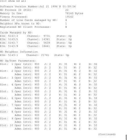
If you enter any parameter except all, a subset of the attributes shown above is displayed.
These steps let you monitor the status of a particular process. You select the process you want to monitor by entering either its number or name.
Step 1 Verify that the target switch is correct by entering the following at the cli> prompt:
show snmp
If you need instructions on changing the target switch, see the section on "Setting the Target Switch for CLI Commands" in the chapter entitled "The Command Line Interface."
Step 2 If you do not know which processes are running, enter the following at the cli> prompt:
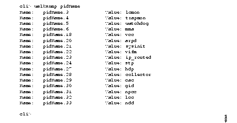
walksnmp pidName
This command lists the process identification (pid) numbers and alias names of all the processes running on this LS2020 switch. The pid numbers follow the term "Name: lwmaTrapCliAlias." and the alias names follow the term "Value" as shown in Figure 4-16.
Step 3 Choose the processes that you want to monitor from this list.
Step 4 To display the status of a particular process, enter the following at the cli> prompt:
show pid {<#>|<alias>} [<parameter>]
where
{<#> | <alias>} = The number of the process or the alias name of the process from which you want to display status.
[<parameter>] = all (default)
name
clialias
createtime
adminstatus
operstatus
traplevel
Figure 4-17 is an example of the display you see when you enter show pid 9 all.
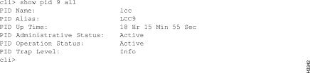
The same information displays when you enter show pid lcc9 (The lcc9 entry is the alias name for process 9).
If you enter any parameter except all, a subset of these attributes displays.
SNMP operation is controlled by a number of parameters that are set to default values when the system is started. These parameters can be changed using the set snmp command. (See the "SNMP Commands" chapter for a discussion of this command.)
To monitor SNMP parameters, enter the show snmp command at the cli> prompt:
The following is an example of the display you see when you enter show snmp.
cli> show snmp
Community: public
HostName:  localhost
cli>
This section provides the steps to monitor the Test and Control System (TCS).
To monitor the values collected by the TCS on a particular card in the chassis, follow these steps. The cards you can monitor are in slots 1 - 10, switch A (SA), and switch B (SB).
Step 1 Verify that the target switch is correct by entering the following at the cli> prompt:
show snmp
If you need instructions on changing the target switch, see the section on "Setting the Target Switch for CLI Commands" in the chapter entitled "The Command Line Interface."
Step 2 Enter the following at the cli> prompt:
show tcs <card #> [<parameter1>] [<parameter2>]
where
<card #> = 1 - 2 for NPs
2 - 10 for line cards
SA and SB for switch cards
Table 4-2 describes <parameter1> and <parameter2>.
| <parameter1> = | <parameter2>1 = |
|---|---|
| all (default) | N/A |
| state | N/A |
| config | all assembly postcode serialnum slavecode type |
| daughter | all assembly serialnum |
| paddle | all assembly serialnum |
| oem | all assembly serialnum |
| midplane | all assembly serialnum nodeaddress |
| temperature | N/A |
| voltage | N/A |
| power | N/A |
| |
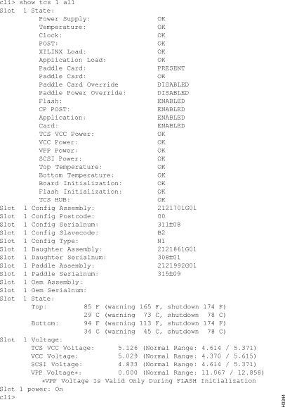
When you enter show tcs 1 all, a display similar to Figure 4-18 displays. If you use any value except all for the argument, a subset of this information displays (see Figure 4-18).
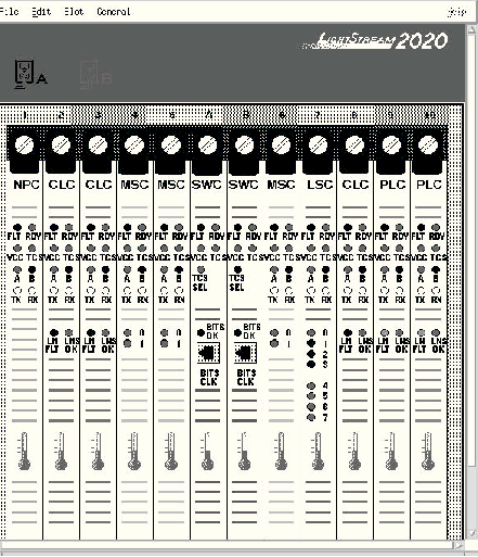
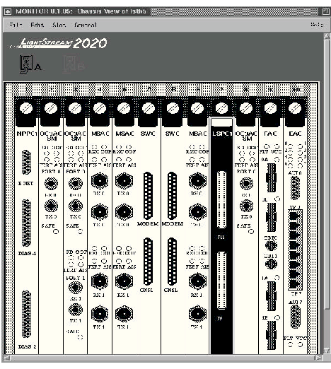
The LS2020 monitor provides a graphical display of individual LS2020 switches, cards, and ports. The display shows the front of an LS2020 switch with bulkheads for the cards as they appear in the actual switch. Information pertinent to the switch displays above the bulkheads. This section explains how to access the monitor to display switches, cards, and ports. You must have a color monitor to use the monitor software.
Step 1 Log in to the NMS workstation.
Step 2 Invoke the LS2020 monitor by selecting it from the HP OpenView menu or by entering the following command at the system prompt:
monitor <chassisname>
where
<chassisname> = the name of the node you want to view
A display similar to Figure 4-19 appears showing the front view of the LS2020 switch, its components, and their status. The area above the bulkhead in the display contains general indicators and summary information about the switch. For a description of the LEDs displayed on each card in the monitor, see the LightStream 2020 Hardware Reference and Troubleshooting Guide.
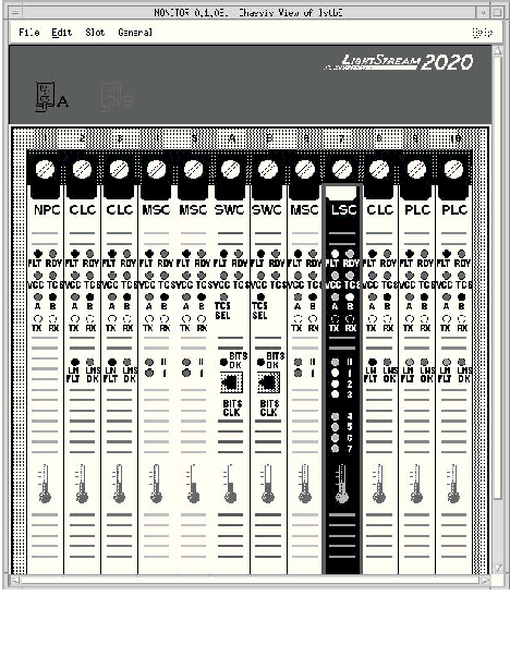
Step 3 To select an object in the display, point the mouse at the object and click on it with the left mouse button. The object appears highlighted. Figure 4-20 shows an LS2020 switch with a selected low-speed line card (LSC).
Step 4 To display the access card for a particular line card, click on the screw above it.
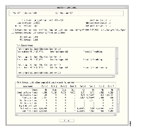
Step 5 To display more information for a particular object in the display, point the mouse at the object and double click with the left mouse button. If more information is available for the object, a screen appears with the relevant information. Figure 4-21 shows a typical monitor card and port information display.
Step 6 Select Show All Access Cards from the Slot menu to obtain a rear view of the switch (see Figure 4-22).
Step 7 To select a menu option from the menus at the top left of your display:
Table 4-3 lists the possible options. All menu options may not be available at all times. Availability depends on the display in the window. Available options are highlighted.
| Menu Name | Options |
| File | Open |
| New Chassis | |
| Exit | |
| Edit | No Options Available |
| Slot | Open Selected Object |
| Show Access Card for Slot | |
| Show Line Card for Slot | |
| Show All Access Cards | |
| Show All Line Cards | |
| General | snmp CLI |
Step 8 You can also display the additional information for an object (discussed in Step 5) by selecting the object with a single click of the left mouse button and then choosing the Open Selected Object option from the Slot menu.
The color of the objects displayed by the monitor provides you with valuable information, as listed in Table 4-4. As you view an object with the monitor, note its color and see the table for an explanation. LEDs on the rear view of the switch are unreadable and appear in white.
| Object | Color | Meaning/Cause |
| LED | Amber | LED is lit. |
| LED | Black | Shut off the machine. Bad connection. |
| LED | Green | LED is lit. |
| LED | Red | Shut off the machine. Over voltage condition exists. Serious power supply problem. |
| LED | White | LED state is unknown. |
| Screw | Black | No information available for card. |
| Screw | Gray | Card is missing. |
| Screw | Red | Card is not operational. (The card has failed or it has been powered off.) |
| Screw | White | Normal card. |
| Any Icon | Red | Abnormal condition. The orange rectangle around a red icon emphasizes the abnormal condition. |
| Any Icon | Yellow | Abnormal condition. The orange rectangle around a yellow icon emphasizes the abnormal condition. |
| Power Supply | Red | Power supply is not operational. |
| Thermometer | Blue | Temperature is within normal range. |
| Thermometer | Red | Temperature is over normal range. Cause unknown. |
| Thermometer | Orange | Temperature is in the warning range. Cause unknown. |
| Thermometer | Yellow | Temperature is in the warning range. Cause unknown. |
Step 9 To iconify a monitor display, click in the Close box in the bar at the top of the window.
The LS2020 topology map application displays a map that represents the actual topology of an LS2020 network. The map is a set of related objects, symbols, and submaps that provide a graphical and hierarchical presentation of the network.
The LS2020 topology map application runs on HP OpenView. If you are not familiar with the HP OpenView Windows product, see the HP OpenView User's Guide. When you start HP OpenView, the LS2020 Topology map application is automatically invoked. Once you start the application, it builds the current LS2020 submap and then periodically polls each LS2020 node for status information. When creating a new HP OpenView map, you can turn off the LS2020 topology function. You must have a color monitor to use the LS2020 topology map application.
The LS2020 topology map provides:
Once the LS2020 submap is created, you can modify it by
You can also show multiple trunk connections, which are represented by meta-connection symbols. The symbol for a meta-connection is <n> where n is the number of connections being represented (see Figure 4-24).
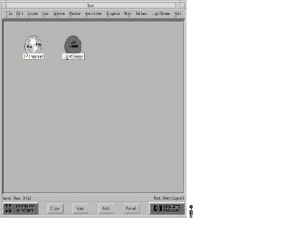
As previously mentioned, once you start HP OpenView, it can create any number of maps and each map is able to be configured to build an LS2020 topology. However, you do not view a map directly. You view the submaps that make up the map. A submap is a particular view of the network environment. Each submap displays a different view of your map. The application creates a Root submap for each LS2020 map. The Root submap provides a standard, top-level submap for every network map.
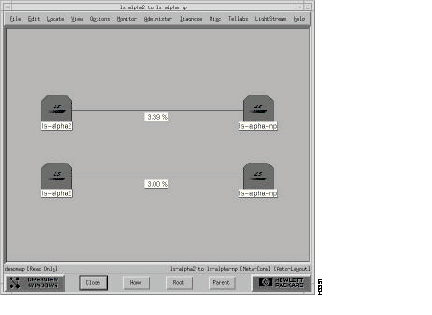
Figure 4-23 shows an example of a Root submap. In this figure, the Root submap contains two symbols: one that represents the Internet and another that represents an LS2020 network.
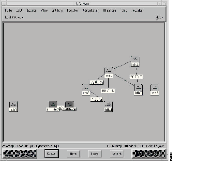
When you open a map, you actually view submaps of the map. To open the LS2020 submap, double click on the LightStream symbol. Figure 4-24 shows a sample LS2020 topology submap.
In this example, the trunk between the ls-alpha2 and ls-alpha-np nodes actually represents two trunks as indicated by the meta-connection symbol <2>.
When a meta-connection is first drawn, its symbol is not displayed. To display a meta-connection symbol (see Figure 4-25), follow these steps.
Step 1 Click the right mouse button on the trunk.
Step 2 Select Describe/Modify Symbol... from the option menu.
Step 3 Select the Display Label.
The next sections describe how to modify the LS2020 submap and view its meta-connection submap.
LightStream domains (logical groups of nodes) can consist of any number of LS2020 nodes. All trunk connections between selected nodes and non-selected nodes are redrawn between the LS2020 domain and the non-selected nodes. Any meta-connections between an LS2020 domain icon and either another LS2020 domain or a node show the two nodes that are connected. When you show an exploded view of an LS2020 domain icon, the nodes that make up the domain and any trunk connections between these nodes are displayed.
To create an LS2020 domain, follow these steps:
Step 1 Select the LS2020 nodes that you want grouped together.
Step 2 Pull down the LightStream menu from the menu bar, and click on Topology...Build Domain.
The selected nodes are removed from the map and replaced by a single domain icon.
When you remove a domain from the topology map, the LS2020 nodes that were originally grouped in that domain are redrawn onto the current submap. To remove an LS2020 domain, follow these steps.
Step 1 Select the domain you want to remove.
Step 2 Pull down the LightStream menu from the menu bar, and click on Topology...Remove Domain.
If you want to remove a node or connection from the LS2020 submap, follow these steps:
Step 1 Double click on the node or trunk that you want to delete.
Step 2 Pull down the Edit menu on the menu bar, and click on Delete.
When you remove a node or trunk connection from the LS2020 submap, it is rediscovered and placed back on the map. To prevent this from happening, click on Hide on the Edit menu. This option keeps a node or trunk connection from being rediscovered and placed back into the submap.
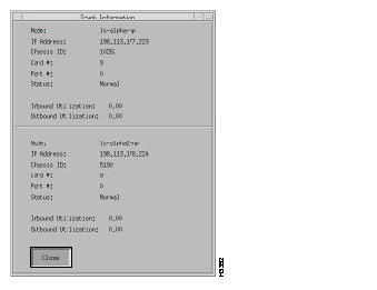
Within the LS2020 submap, a trunk connection is displayed including its interface bandwidth. If you want to get chassis, port, and utilization information about this connection, you click the left mouse button on a trunk. A pop-up dialog box appears and information similar to the following displays (see Figure 4-26).
The LS2020 Topology Manager periodically queries each LS2020 node for its trunk information to see if new trunks have been added or known trunks have been removed. It also communicates with HP OpenView for any new objects that are discovered. If new objects are found, the LS2020 Topology Manager (LTM) checks to see if the object's SysOid number matches its own.
The LS2020 submap attributes that you can modify are
The next sections provide a brief description of the attributes and the steps for changing them.
You can modify these attributes from either the OpenView Root dialog box or the LS2020 Submap dialog box.
Step 1 Pull down the File menu on the menu bar, and click on Describe/Modify Map. The Map Description dialog box appears (see Figure 4-27).
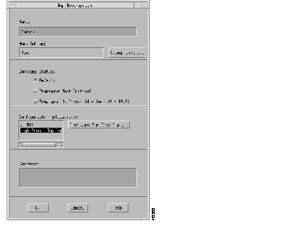
Step 2 Click on the appropriate entry in the Configurable Applications list.
Step 3 Click on the Configure for this Map button. For example, if you click on the LS2020 Topology Map, the Configuration box appears (see Figure 4-28).
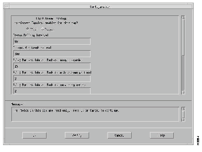
From the Configuration box, you can enable or disable the LS2020 Topology Manager (LTM) and select the attributes that you want to modify, such as status polling interval, timeout for trunk removal, and so on.
The default is to enable the LS2020 Topology Manager (LTM) when you start HP OpenView.
The LS2020 topology map application polls each LS2020 node periodically for status information (the default polling time is 60 seconds).
Status changes in the network are displayed through changing colors on the network map and writing messages to HP OpenView Alert window.
Table 4-5 lists the possible status conditions of a node in the network and their meanings. Table 4-6 lists the same information for a trunk connection in the network.
| Status | Meaning |
| Unknown | Unable to access the node through SNMP. |
| Critical | One of the following problems has been detected: a chassis ID conflict, a bad power supply, abnormal temperature, or a diagnostic error on a card. |
| Major | One or more cards within the node reported a down operational status. |
| Marginal | One of the following problems on an edge port has been detected: congestion, high error rate, large amount of discarded traffic, or attempt to use an improperly configured PVC. If any of these problems is detected, a message appears in the HP OpenView Events window. Note that for release 2.1 edge port monitoring is turned off. |
| Normal | No known problems detected. |
| Unmanaged | The user has configured the node to be unmanaged. |
| Status | Meaning |
| Critical | The ifOperStatus reported down for either port in the connection, or the trunk is no longer being discovered in the GID table. |
| Testing | The ifOperStatus reported testing for either port in the connection. |
| Normal | No known problems detected. |
| Major | One of the following problems on either of the ports on the trunk connection has been detected: high number of packets being discarded, high trunk utilization, high error rate, or attempt to use an improperly configured PVC. If any of these problems is detected, a message appears in the HP OpenView Events window. |
| Warning | One of the following problems on either of the ports on the trunk connection has been detected: high number of packets with unknown protocols being received or the output queue length is excessively high. |
| Unmanaged | The user has configured the trunk to be unmanaged. |
Unknown | Unable to get port information through SNMP. |
|---|
The default for the timeout for trunk removal attribute is 300 seconds.
The LS2020 topology map application collects information for each interface to determine the condition of the LS2020 network. There are rule definitions that apply to the data collected. For example, the default value for the percent inbound packets being discarded is 15%. If the percent of packets being discarded exceeds either the default value or the value you set, a message gets logged to the HP OpenView Alert window. You can change the rate of the default value according to your network needs. Table 4-7 lists the rules and their default values that are applied to the data collected.
| Rule | Default Value |
|---|---|
| Percent inbound packets being discarded | 15% |
| Percent inbound packets with unknown protocol | 2% |
| Percent inbound packets containing errors | 2% |
| Percent outbound packets being discarded | 15% |
| Percent outbound packets containing errors | 2% |
| High output queue length | 10 |
Marginal status indications for nodes and major status indications for connections indicate potential network integrity problems. Once a problem is discovered, such as a large number of packets being discarded, the appropriate status is set. The status remains in effect until a time period (the default is 5 minutes) elapses without the problem being rediscovered. To change the default, select the File...Describe/Modify Map menu item.
In an LS2020 network, traffic shaping is applied at all packet interfaces, as shown in Figure 4-6. Traffic entering ATM UNI interfaces does not need to be shaped, since it obeys the traffic policing parameters set for each virtual circuit.
|
|