|
|

This chapter describes how to change configuration attributes using the CLI. Normally, these changes are made to run-time memory only. If the switch is reset, the changes are overwritten by the attribute settings in the configuration database.
The modem password and the modem initialization string are stored in EEPROM in the midplane. The default modem password is
atmhiway
the default modem initialization string is
AT&F&D2&C1&Q0S0=1S2=128S7=30S36=7S95=44
You may retain these default values. If you change them, the changes you make are permanent and remain in effect unless you change them again. Rebooting the system or restarting the CLI does not change the modem password or the modem initialization string.
If you change the modem password or the modem initialization string for one switch card slot, make the same change for the other. This is especially important for a two-card system because the backup switch card takes over if the active switch card fails. It is also important for a single switch card system because you may want to add an additional switch card later or you may decide to move the single switch card to the other slot.
You must have a switch card in the switch card slot to change the modem password or the modem initialization string. Therefore, if you have only one switch card, move it from one switch card slot to the other as you effect the change for both slots.
To change the default modem password and the modem initialization string, follow these steps:
Step 1 Enter the protected command at the cli> prompt.
Step 2 Enter the protected mode password when you see the following prompt:
Step 3 To verify that the target switch is correct, enter the show snmp command at the *cli> prompt.
If you need instructions on changing the target switch, see "Setting the Target Switch for CLI Commands" in the chapter entitled "Command Line Interface."
Step 4 To change the modem password, enter the following at the *cli> prompt:
*cli> set modem <slot #> password <password>
Where
<slot #> is the slot number for the switch card (SA or SB) whose modem password you are changing.
<password> is the new modem password.
Step 5 To change the modem initialization string, enter the following at the *cli> prompt:
*cli> set modem <slot #> initstring <initstring>
Where
<slot #> is the slot number for the switch card (SA or SB) whose modem initialization string you are changing.
<initstring> is the new modem initialization string. The format of the modem initialization string should be the same as the default modem initialization string. The content of the modem initialization string depends on the type of modem you are using. Refer to the documentation for your modem to determine the contents of the modem initialization string.
Step 6 To verify the contents of the modem password and the modem initialization string, enter the following at the *cli> prompt:
*cli> show modem <slot #> all
The password and the modem initialization string are permanently changed. Inform all authorized users of the changes you make.
Different types of modems require different modem initialization strings. If you have different modems connected to each switch card, the init strings may be different. The passwords may or may not be different.
Inform authorized users of the changes you make.
You can change this password from within protected mode only.
To change the protected mode and npadmin password, follow these steps:
Step 1 Enter the protected command at the cli> prompt.
Step 2 Enter the protected mode password when you see the following prompt:
The *cli> prompt appears to indicate that you are in protected mode.
Enter the password command at the *cli> prompt.
Step 3 Enter the protected mode password when you see the following prompt:
Step 4 Enter the new protected mode password when you see the following prompt:
The password must contain at least six alphanumeric characters.
Step 5 Retype the new protected mode password when you see the following prompt:
If you retype the new password correctly, the system changes the password and displays the *cli> prompt.
If you enter an inappropriate password, one or more of the following messages may appear:
Inform all authorized users of the changes you make.
Each SNMP manager (the CLI, for example) and each managed system (the MMA in an LS2020 switch, for example) has a community name. The SNMP manager specifies a community name in each command it sends. The managed system validates the commands before executing them by comparing the community name in the command against its own community name.
Before you can set attributes or use the CLI control commands, you must set the SNMP community to a community that has read/write access privileges. The read/write community provided with the system is named write. (A switch can have several SNMP community names with read/write privileges.) The read-only community provided with your system is named public.
To prevent unauthorized access to your system, you should set the SNMP community names that the LS2020 switch uses to validate the commands before it executes them. Follow the procedure below to set the SNMP community name that the CLI puts in commands.
Step 1 At the cli> prompt, enter
set snmp community <name>
Where
<name> is the name for the SNMP community with read/write privileges that you want to access.
Step 2 To verify the SNMP community name, enter the show snmp command at the cli> prompt.
The community name is set to the SNMP community you specified.
The SNMP community reverts to the read-only community when you log out of the CLI. However, if you leave your terminal without logging out of the CLI, be sure to change the SNMP community back to the read-only community to prevent unauthorized access to your system.
The LS2020 switch uses the spanning tree protocol to detect loops within a bridged network. When a loop is detected, one port on the bridge performs a blocking function to break the loop. All bridging traffic on that port is discarded and MAC address learning is not performed. This section provides the steps to define and display spanning tree bridging parameters and static filters using the CLI show and set commands.
To define and display spanning tree bridge parameters, follow these steps:
Step 1 To verify that the target switch is correct, enter the show snmp command at the cli> prompt.
Step 2 To view the current general spanning tree bridge parameters, enter the following at the cli> prompt:
show stb general
A screen similar to the following is displayed:
Step 3 To set the spanning tree timeout parameters, enter the following commands at the cli> prompt:
set stb maxage <maxagevalue>
Where
<maxagevalue> is the maximum interval that is used to time out spanning tree information.
set stb hellotimer <hello-timer-val>
Where
<hello-timer-val> is the time interval between Hello BPDUs.
set stb forwdelay <fwd-delay-val>
Where
<fwd-delay-val> is the time interval to be used before changing to another state.
set stb priority <priority>
Where
<priority> is the priority for using this node versus others for a path using the Spanning Tree Protocol. The range is 0 to 65535, and the default is 32768.
Step 4 To verify that the spanning tree parameter changes have been made, enter the following at the cli> prompt
show stb general
The changes appear in the display. The spanning tree parameters are set as you specified.
To make entries into the bridge filtering database, follow these steps:
Step 1 To verify that the target switch is correct, enter the show snmp command at the cli> prompt.
If you need instructions on changing the target switch, see "Setting the Target Switch for CLI Commands" in the chapter entitled "Command Line Interface."
Step 2 To view the current statically entered spanning tree bridge filtering entries, enter the following at the cli> prompt:
show stb static
Step 3 To make entries into the spanning tree bridge static filtering database, enter the following at the cli> prompt:
set stb static <MACaddr> rcv <rcv-port> xmit <xmit-port(s)>
Where
<MACaddr> is the MAC address. The MAC address must be entered in xx:xx:xx:xx:xx:xx (hex) format.
<rcv-port> is the port to which this MAC address is assigned. This may be an ifIndex (for example, c.p) or the keyword any.
<xmit-port> is the comma-separated list of ports to which received frames are to be forwarded.
Step 4 To verify that your entries have been made, enter the following at the cli> prompt:
show stb static
Your entries should appear in the display.
Step 5 To view the spanning tree bridge forwarding table entries and their associated variables, enter the following at the cli> prompt:
show stb fwd
The entries appear in the display.
Step 6 To view bridge port information, enter the following at the cli> prompt:
show stb ports
LS2020 custom filtering allows you to define filters to block or forward incoming packets for specific ports. A filter is a set of conditions that is compared to information in the header of incoming packets. As an incoming packet is received, its level 2 and level 3 headers are broken into components. The header information is evaluated against all filters (in priority order) associated with the receiving port. If a filter condition matches the header information, the action specified by that filter is taken. If the filter condition does not match the packet header information, the next filter is evaluated. If no filter conditions match the packet header information, the default action for the port is taken.
You must first define the traffic filter (bridge filter, IP filter, or IPX filter) and then assign the filter with a port or ports. Optionally, you can associate a multicast group and traffic profile to a filter or a port. You must define a filter, a multicast group, and a traffic profile before you can assign that filter to a specific port.
To define a custom traffic filter, you assign a number to the filter and write the filter expression. The next sections discuss defining traffic filters, multicast groups, and traffic profiles and assigning filters to a specific port.
For a description of filter attributes, construction, and examples, see the LightStream 2020 CLI Reference Manual.
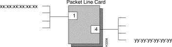
The following steps define sample traffic filters that block the LAN end stations in Figure 5-1 from communicating with each other. To successfully block the communications, filters must be created for the ports (1 and 4) supporting each LAN.
Step 1 Set the SNMP community to write.
Step 2 To determine if any filters are currently defined for either of these ports, enter the following at the cli> prompt:
show port <c.p> {bflt|ipflt|ipxflt} [ID]
Where
<c.p> is the card and port number in card.port format
(card = 2 to 10; port = 0 to 7)
{bflt | ipflt | ipxflt} is a bridge filter, IP filter, or IPX filter, respectively.
[ID] (optional) is the number that identifies the filter whose contents are to be displayed.
Step 3 To display a current filter, enter the following at the cli> prompt:
show {bflt|ipflt|ipxflt} [ID]
Where
{bflt | ipflt | ipxflt} is a bridge filter, IP filter, or IPX filter, respectively.
[ID] (optional) is the number that identifies the filter whose contents are to be displayed.
If you want to display all traffic filters, leave off the ID number.
Step 4 To define the new filter for port 1, blocking all traffic from the source end station (xx:xx:xx:xx:xx:xx) that is directed to the destination end station (yy:yy:yy:yy:yy:yy), enter the following at the cli> prompt:
define bflt <ID> (macDst == yy:yy:yy:yy:yy:yy) && (macScr == xx:xx:xx:xx:xx:xx)
Where
<ID> is the identifying number that you assign to the filter.
Step 5 To define the new filter for port 4, blocking all traffic from the source end station (yy:yy:yy:yy:yy:yy) that is directed to the destination end station (xx:xx:xx:xx:xx:xx), enter the following at the cli> prompt:
define bflt <ID> (macDst == xx:xx:xx:xx:xx:xx) && (macSrc == yy:yy:yy:yy:yy:yy)
You must now assign each filter to the appropriate ports.
Step 6 To assign the appropriate filter with port 1, enter the following at the cli> prompt:
set port <c.p> {bflt|ipflt|ipxflt} <ID> {block|forward} <priority>
[tprof <ID>] [mcast <ID>]
Where
<c.p> is the card and port number in card.port format
(card = 2 to 10; port = 1).
<ID> is the identifying number that you assigned to the filter.
{block | forward} is the action to be taken when the frame value matches the filter value (one of forward or block).
<priority> is the priority number applied to this filter. The filter is added to a priority list according to this value. Incoming frames are compared to the filters in priority order. One is the highest priority. It is recommended that you assign the priorities by 10s (10, 20, 30, and so forth) to leave ample numbers available for the reordering or adding of filter assignments.
[tprof <ID> is the word "tprof" followed by the traffic profile ID associated with the specified port for traffic forwarded by the specified filter.
[mcast <ID>] is the word "mcast" followed by the multicast group ID associated with the specified port for traffic forwarded by the specified filter.
Step 7 To assign the appropriate filter with port 4, enter the following at the cli> prompt:
set port <c.p> bflt [ID] block <priority>
Where
<c.p> is the card and port number in card.port format
(card = 2 to 10; port = 4).
[ID] is the identifying number that you assigned to the filter.
block is the action to be taken when the frame value matches the filter value.
<priority> is the priority number applied to this filter. The filter is added to a priority list according to this value. Incoming frames are compared to the filters in priority order. One is the highest priority. It is recommended that you assign the priorities by 10s (10, 20, 30, and so forth) to leave ample numbers available for the reordering or adding of filter assignments.
If the default for both of these ports is to forward, then all other traffic is allowed (unless, of course, other filters have been defined to block certain traffic).
Step 8 To verify that the filters have been assigned, enter the following at the cli> prompt:
show bflt
show port <c.p> {bflt|ipflt|ipxflt}
<c.p> is the card and port number in card.port format
(card = 2 to 10; port = 0 to 7).
The filters you created now block traffic from being sent between the end stations on the LANs.
A multicast group is a list of destination ports on nodes in the network. Traffic that matches an associated filter condition is sent to each member of the group. Only one multicast group may be associated with any given filter on a given port, and the action of the filter must be forward. These steps describe how to define the multicast group parameter for a filter:
Step 1 To determine if any multicast groups have been created, enter the following at the cli> prompt:
show mcast [ID]
Where
ID is the identification number by which the filter is identified, in the range 1to 255.
If you do not give an ID argument, then all defined multicast groups are displayed.
Step 2 To define the multicast group parameter for a filter, enter the following at the cli> prompt:
define mcast ID [node:]c.p [[node:]c.p...]
Where
ID is the identification number by which the filter is identified, in the range 1to 255.
[node:]c.p [[node:]c.p...] specifies a port on an LS2020 node.
If you do not specify a node, it defaults to the current node.
A traffic profile is a set of type-of-service attributes that can be applied to traffic flows by associating the profile with a filter. Only one profile can be associated with any given filter on any given port, and the action of the filter must be forward. These steps describe how to define the traffic profile parameter for a filter:
Step 1 To determine if any traffic profiles have been created, enter the following at the cli> prompt:
show tprof [ID]
Where
ID is the identification number by which the filter is identified, in the range 1to 255.
If you do not give an ID argument, all current traffic profiles display.
Step 2 To define a traffic profile parameter enter the following at the cli> prompt:
define tprof ID arguments
Where
ID is the identification number by which the filter is identified, in the range 1to 255.
arguments are max-rate, max-burst, insured-rate, insured-burst, principal-service-type, secondary-scale, transmit-priority
If you do not give an ID argument, all current traffic profiles display.
For a description of the previously listed arguments, see the LightStream 2020 CLI Reference Manual.
Any filter can be assigned to any port (which is up and running) at any time. Incoming packets for that port are subsequently compared with the filter conditions. If the value of a specific field in the packet header matches the value of the filter, the action specified by the filter condition is taken.
To associate a filter with a specific port or ports, follow these steps:
Step 1 To view the filters currently defined for a specific port, enter the following at the cli> prompt:
show <c.p> {bflt|ipflt|ipxflt}
Where
<c.p> is the card and port number in card.port format
(card = 2 to 10; port = 0 to 7).
{bflt | ipflt | ipxflt} is a bridge filter, IP filter, or IPX filter, respectively.
Step 2 To associate the filter with a specific port, enter the following at the cli> prompt:
set port <c.p> {bflt|ipflt|ipxflt}
<filter ID> {block|forward} <priority>
Where
<filter ID> is the number that identifies the filter being assigned to the port.
{block | forward} is the action that is taken when the frame value matches the filter value (forward or block).
<priority> is the priority number applied to this filter. The filter is added to a port filter list according to its priority. Incoming frames are compared to the filters in priority order. One is the highest priority. It is recommended that you assign the priorities by 10s (10, 20, 30, and so forth) to leave ample numbers available for the reordering or adding of filter assignments.
This procedure describes how to define the default filter action for a specific port. This determines the action to take with incoming traffic (forward or block) when incoming traffic matches none of the defined filter conditions.
Step 1 To view the current default filter action parameter for a specific port, enter the following at the cli> prompt:
show port <c.p> {bflt-def|ipflt-def|ipxflt-def}
Where
<c.p> is the card and port number in card.port format
(card = 2 to 10; port = 0 to 7).
Step 2 To define or alter the default filter action parameter for this port, enter the following at the cli> prompt:
set port <c.p> {bflt-def|ipflt-def|ipxflt-def} {block|forward}
Where
<c.p> is the card and port number in card.port format
(card = 2 to 10; port = 0 to 7).
{bflt | ipflt | ipxflt} is a bridge filter, IP filter, or IPX filter, respectively.
{block | forward} is the action that is taken when the frame value matches the filter value (forward or block).
Step 3 To verify the change, enter the following at the cli> prompt:
show port <c.p> {bflt-def|ipflt-def|ipxflt-def}
This procedure describes how to define the default broadcast limit parameter for a specific port. It applies only to bridge filters.
Step 1 To view the current default broadcast limit parameter for a specific port, enter the following at the cli> prompt:
show port <c.p> bcast-limit
Where
<c.p> is the card and port number in card.port format
(card = 2 to 10; port = 0 to 7).
Step 2 To define or alter the default broadcast limit parameter for this port, enter the following at the cli> prompt:
set port <c.p> bcast-limit {discard-all|forward-all|packets/sec}
Where
<c.p> is the card and port number in card.port format
(card = 2 to 10; port = 0 to 7).
<bcast-limit> is the rate at which broadcast packets can be forwarded through the bridged LAN port. Excess broadcast packets are dropped.
<discard-all> means discard all broadcast packets sent to this port.
<forward-all> means forward all broadcast packets to this port.
<packets/sec> is the maximum number of broadcast packets per second to be forwarded through this port, in the range of 1to 127.
To restore the default broadcast limit, enter the above command with forward all as the number of packets per second.
To disassociate a filter from a specific port or ports, follow these steps:
Step 1 To view the filters currently defined for a specific port, enter the following at the cli> prompt:
show port <c.p> {bflt|ipflt|ipxflt}
Step 2 To break the association between a filter and a port, enter the following at the cli> prompt:
set port <c.p> {bflt|ipflt|ipxflt} <filter ID> delete
Where
<c.p> is the card and port number in card.port format
(card = 2 to 10; port = 0 to 7).
{bflt | ipflt | ipxflt} is a bridge filter, IP filter, or IPX filter, respectively.
<filter ID> is the number that identifies the filter being assigned to the port.
This command removes the specified filter from the list of filters associated with a port. The filter is still defined but no longer affects traffic on the specified port.
Step 3 To verify that the association was removed, enter the following at the cli> prompt:
show port <c.p> {bflt|ipflt|ixpflt}
This procedure describes how to delete a filter. You cannot delete a filter that is associated with a port. You must first perform the procedure "Deleting the Association Between a Filter and a Port " as previously described.
Step 1 To view the currently defined filters, enter the following at the cli> prompt:
show {bflt|ipflt|ipxflt}
Step 2 To view the filters currently defined for a specific port, enter the following at the cli> prompt:
show port <c.p> {bflt|ipflt|ipxflt} <filter ID>
Where
<c.p> is the card and port number in card.port format
(card = 2 to 10; port = 0 to 7).
{bflt | ipflt | ipxflt} is a bridge filter, IP filter, or IPX filter, respectively.
<filter ID> is the number that identifies the filter being assigned to the port.
Step 3 To delete a filter, enter the following at the cli> prompt:
delete {bflt|ipflt|ipxflt} <filter-id>
Where
<filter-id> is the number that identifies the filter.
Step 4 To verify that the filter was deleted, enter the following at the cli> prompt:
show {bflt|ipflt|ipxflt}
The filter you deleted should not appear in the display.
Virtual LAN Internetworking (VLI) allows you to transcend the physical limitations of LAN internetworking. The LS2020 configurator lets you arrange stations in distinct workgroups and to restrict access between workgroups. Stations on different physical segments can belong to the same workgroup, and they can belong to more than one workgroup. For further information, see the LightStream 2020 Configuration Guide.
You establish the default workgroup by having no workgroup IDs at all in an exclude list; that is, excluding no one. An exclude list that is not empty includes everybody except those that have at least one of the listed workgroup IDs in their include list. An include list admits only those that have at least one of the listed workgroup IDs in their include list. An empty include list blocks all communications.
Step 1 To create an include list, enter the following at the cli> prompt:
set port <c.p> wgrp include
Where
<c.p> is the card and port number in card.port format
(card = 2 to 10; port = 0 to 7).
Step 2 To create an exclude list, enter the following at the cli> prompt:
set port <c.p> wgrp exclude
To add a workgroup ID to a list for a specific port, follow these steps:
Step 1 To verify that the target switch is correct, enter the show snmp command at the cli> prompt.
If you need instructions on changing the target switch, see "Setting the Target Switch for CLI Commands" in the chapter entitled "Command Line Interface."
Step 2 To add a workgroup to the list for the port, enter the following at the cli> prompt:
set port <c.p> wgrp add <wgrp#>
<c.p> is the card and port number in card.port format
(card = 2 to 10; port = 0 to 7).
<wgrp#> is the number that identifies the workgroup.
Step 3 To verify that the workgroup was added to the list, enter the following at the cli> prompt:
show port <c.p> wgrp
A screen similar to the following is displayed.
show port <c.p> wgrp
To delete a workgroup from a list for a specific port, follow these steps:
Step 1 To view the workgroups currently defined for a specific port, enter the following at the cli> prompt:
show port <c.p> wgrp
Where
<c.p> is the card and port number in card.port format
(card = 2 to 10; port = 0 to 7).
<wgrp#> is the number that identifies the workgroup.
Step 2 To disassociate the workgroup from a port, enter the following at the cli> prompt:
set port <c.p> wgrp del <wgrp#>
Step 3 To verify that the association was removed, enter the following at the cli> prompt:
cli> show port <c.p> wgrp
A screen similar to the following is displayed:
|
|