|
|

In a LightStream 2020 multiservice ATM switch (LS2020 switch), all traffic that passes over the network is connection-oriented. This means that connections must be established before any traffic (ATM cells) can be transmitted or received. This chapter describes connections in an LS2020 network.
The call admission control mechanism determines whether the network can support a requested virtual channel connection (VCC). An LS2020 network establishes requested VCCs through one of two methods:
Provisioning is the explicit creation of a VCC in which a user specifies its endpoints and other attributes in a configuration database. Provisioned VCCs are called permanent virtual circuits (PVCs).
When you specify the endpoints of a connection, the LS2020 network automatically sets up a pair of VCCs to provide bidirectional communication between the two endpoints. For each VCC, you can configure a separate set of traffic management parameters, including bandwidth.
A VCC is implicitly established when a module recognizes the need for a new connection. For example, when a LAN port on an Ethernet interface module does not recognize an incoming packet as belonging to an existing VCC, the system creates a new VCC and routes the data across the connection. After a period of inactivity, the system tears down the VCCs so they no longer consume network resources.
An LS2020 switch provides the following methods of connecting external devices to the network and passing traffic through the network:
These services are described separately in the following sections.
The LS2020 ATM user network interface (UNI) service supplies an ATM interface that allows non-LS2020 ATM networks or other ATM-capable devices to use the LS2020 backbone network. The LS2020 ATM UNI interface conforms to the structure and field encoding conventions defined by the American National Standards Institute (see Table 2-1). The ATM UNI is managed through the use of structures in the standard Management Information Base (MIB) and the LS2020 enterprise-specific MIB.
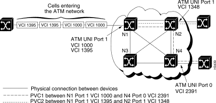
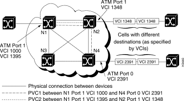
An ATM UNI PVC is defined by two endpoints (ATM ports) on the edges of the network and the local virtual channel identifiers (VCIs) associated with the particular PVC that runs between the source port and the destination port. (The VCI is a number used by an ATM device to identify a virtual channel link that makes up a part of the virtual channel connection.) Figure 3-1 shows two ATM UNI PVCs: PVC 1, and PVC 2.
It is not necessary for the LS2020 switch to segment incoming traffic into ATM cells, because the traffic exists in this form on arrival. The LS2020 switch looks at the VCI in the arriving ATM cells and determines the PVC on which the traffic should be passed. Each cell is passed through the network on the selected PVC. When the cells reach the final LS2020 switch in the PVC, they are passed out of the LS2020 network on the correct destination port and VCI.
Figure 3-2 shows ATM cells entering an LS2020 network; Figure 3-3 shows the ATM cells exiting the LS2020 network.
An LS2020 network supports transparent and translation bridging. Specifically, it supports Ethernet-to-Ethernet, FDDI-to-FDDI, and Ethernet-to-FDDI bridging within a switch, as well as across the ATM network.
LS2020 bridging is implemented as a cell internet with underlying ATM features (see the following subsections). Bridging services also include the following features, each of which is described later in this section:
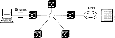
From a user's point of view, an LS2020 network can be understood as a collection of bridges connected through the ATM backbone with one bridge per LS2020 switch. Externally, all the bridges in the network appear to be sharing a single broadcast medium on the inside of the ATM network. Each bridge in an LS2020 network has one internal connection to an internal broadcast backbone. Figure 3-4 shows the LS2020 bridging model.
If you want to overlay a connectionless service such as bridging on an ATM network infrastructure, the LS2020 network automatically manages bandwidth and VCCs for bridged traffic. These operations are invisible to the user of the network. The LS2020 switch supports the following ATM services:
The LS2020 bridging model is structured so that loops cannot occur in a network composed solely of LS2020 switches. However, spanning-tree support is required for interoperability with bridges from other vendors. Ports that are configured for bridging implement the spanning-tree algorithm defined in IEEE 802.1d. The algorithm eliminates loops that may be caused by external bridges or incorrect cabling attached to multiple LS2020 ports.
The logical network that the algorithm creates is always a spanning tree with the following characteristics:
If the spanning-tree protocol detects a loop, one of the ports on the bridge goes into a blocking state to break the loop. While in the blocking state, the port discards all bridged traffic and stops learning Media Access Control (MAC) address information.
The LS2020 bridge supports custom filters on LAN interfaces. You create custom filters and assign them to ports using either the LS-Configurator or the CLI. Based on the filters applied to a port, the bridge drops or forwards incoming frames. You could, for instance, prohibit a particular protocol from passing between two ports by creating the appropriate filter for each port.
You create custom filters on a per-chassis basis. Creating a custom filter consists of defining the filter and then assigning the filter to a port or ports. You can assign multiple filters to one port, and you can assign the same filter to multiple ports. Custom filtering is applicable only at inbound ports.
Before you can create custom filters, you must configure a chassis and at least one FDDI, Ethernet, or Fiber Ethernet card with its associated ports.
The LS2020 bridge custom filtering capability for LAN flows supports the following:
For information about how to configure custom filters, see the LightStream 2020 Configuration Guide.
The LS2020 bridging software supports static filtering (also called static bridge forwarding as defined in IEEE 801.d). Through the LS-Configurator or the CLI, you can make static entries in the bridge's filtering database. You may, for instance, want to make a static entry if you are directing a broadcast to specific ports in order to limit broadcast propagation. You would also make a static entry if you have an end station that only receives traffic, in which case the bridge cannot learn about the station.
For information about how to configure static filters, see the LightStream 2020 Configuration Guide.
The LS2020 bridging software provides the following capabilities to limit the amount of broadcast traffic on the network:
The following three sections describe VirtualStream, the Cisco Systems suite of virtual LAN internetworking facilities:
AS/QoS allows you to assign traffic management attributes to LAN flows. By associating a traffic profile with a custom filter, you can determine which LAN flows should receive a specific type of service. These types of services are configurable.
For example, you can configure the following traffic profile parameters:
For more information about setting a traffic profile, see the LightStream 2020 Configuration Guide.
High-performance multicast service (HPMS) allows multicast and broadcast flows to be sent across an LS2020 network at wire speed. This feature supports multicast groups. Multicast groups (lists of destination ports) deliver LAN traffic using an ATM point-to-multipoint VCC. Members of multicast groups may be anywhere in the network and need not have the same media type. For example, members can have a mix of Ethernet and FDDI ports. Furthermore, members can have multiple multicast groups, and a LAN port can belong to multiple groups.
When you assign a custom filter to a port, the port may have associated with it a multicast group, assuming the action of the filter is to forward the matching LAN flow. At this time, a traffic profile must be assigned to it. You are provided with a set of default parameters for the traffic profile associated with the multicast group, which may be used instead of explicitly configured traffic profile parameters.
When a LAN flow matching that custom filter is detected, a point-to-multipoint VCC is created from that source port to each of the ports in the multicast group. If the source is also a member of the multicast group, it is not included as a destination of the point-to-multipoint VCC.
You cannot modify the definition of a multicast group while the multicast group is assigned to a filter. If you want to define a new multicast group (with a different ID), you need to change the assignment for the filter to the new ID. When you do this, the active flows terminate and rebuild with the new multicast group configuration.
For more information about assigning multicast groups, see the LightStream 2020 Configuration Guide.
A workgroup is a collection of LAN ports that are allowed to communicate with each other. By assigning groups of ports to different workgroups, you can provide privacy between groups or limit the impact of one group's traffic on another. The workgroup membership for a port defines the membership of all the stations attached to the port.
You can create workgroups through the StreamView configurator or the CLI. By default, all ports in the network are assigned to a single workgroup. This makes the default behavior the same as that of an ordinary bridged network.
In an LS2020 network, ports can
Figure 3-5 shows a typical workgroup configuration.
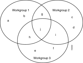
Ports a, b, c, d, e, and f belong to only one workgroup; they can communicate only with other ports in that workgroup.
Ports g, h, and i belong to two workgroups; therefore, they can communicate with ports in either of those workgroups.
Port j belongs to all three workgroups; therefore, it can communicate with all the other ports.
For more information about workgroup configuration, see the LightStream 2020 Configuration Guide.
The LS2020 supports a Frame Relay DCE interface to which you can connect routers, packet switches, and other devices that have Frame Relay DTE interfaces. It also supports a Frame Relay network-node interface (NNI) to which you can connect other Frame Relay switches or networks.
Using the Frame Relay service, the LS2020 network can accept traffic at a single port and send that traffic to multiple destinations. This contrasts with the Frame Forwarding service, in which all traffic received on a particular port is sent to one destination port.
A Frame Relay PVC is defined by two endpoints (Frame Relay ports) on the edges of the network and the local data link connection identifiers (DLCIs) associated with those endpoints. The LS2020 network uses the DLCI associated with each frame of the traffic to determine its PVC. The LS2020 switch then segments each frame into cells and sends it to its destination.
Figure 3-6 shows three Frame Relay PVCs. As the figure indicates, there can be more than one Frame Relay PVC between the same LS2020 switches.
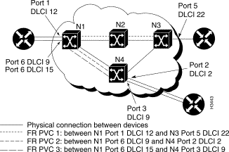
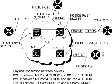
Figure 3-7 and Figure 3-8 show how frames with multiple destinations are received on one port and passed through the LS2020 network to their correct destinations.
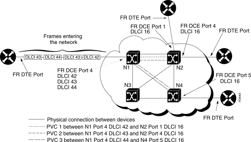
The LS2020 switch at which the traffic enters looks at each frame's DLCI and determines the PVC on which the traffic should be passed. The frame is then segmented into cells. Each cell is passed through the network on the selected PVC. When the cells reach the final LS2020 switch in the PVC, they are reassembled into a frame and passed out of the LS2020 network on the correct destination port and DLCI (see Figure 3-8).
Frame Forwarding services let you replace direct connections between devices that support HDLC and SDLC with a connection through the LS2020 network. This allows you to connect older devices that do not support Frame Relay, ATM UNI, or LAN interfaces. For example, you can use the Frame Forwarding service to connect X.25 packet-switching nodes or SNA devices through the LS2020 network.
Frame Forwarding PVCs provide a "virtual wire" between two network ports on the edge of the LS2020 network. All traffic that enters the LS2020 network on a particular Frame Forwarding port is sent through the network to the port on the other end of the virtual wire. All traffic that enters the network on a particular Frame Forwarding port must have the same destination on the other side of the LS2020 network.
Unlike circuit-switched connections, which require permanent reservation of the bandwidth needed between the two ports, the Frame Forwarding function uses only internal network bandwidth when there is an actual frame to be sent and does not use any bandwidth during interframe gaps.
A Frame Forwarding PVC is defined by two endpoints (Frame Forwarding ports) on the edges of the network. Figure 3-9 shows two Frame Forwarding PVCs, numbered 1 and 2. The endpoints of
PVC 1 are Port 1 on N1 and Port 3 on N3. The endpoints of PVC 2 are Port 2 on N1 and Port 6 on N4. There may be any number of LS2020 switches between the endpoints. The LS2020 network selects the best route between the two endpoints and sends the ATM cells along that route.

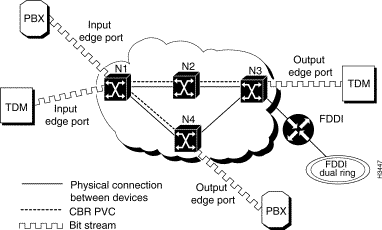
Circuit emulation services let you interconnect existing T1/E1 interfaces and other kinds of constant bit rate (CBR) equipment. Some CBR services include such features as PBX interconnect, consolidated voice and data traffic, and video conferencing.
With circuit emulation, data received from an external device at the edge of the LS2020 network is converted to ATM cells, sent through the network, reassembled into a bit stream, and passed out of the LS2020 network (see Figure 3-10). T1/E1 circuit emulation does not interpret the contents of the data stream. All the bits flowing into the input edge port of the ATM network are reproduced at one corresponding output edge port.
An emulated circuit is carried across the LS2020 network on a PVC, which is configured through the network management system.
When equipped with appropriately configured hardware, software, and network management tools, an LS2020 switch can be used to globally synchronize constant bit rate (CBR) interfaces in an LS2020 network to a central reference clock signal. This network timing distribution service, called Nettime, enables synchronous clocking and synchronous residual time stamp (SRTS) clocking functions to be accomplished through an LS2020 switch.
Network timing services depend on specific hardware capabilities in an LS2020 switch. The Nettime facility requires the presence of at least one Release 2 switch card in the chassis, as well as one or more Nettime-capable access cards. A Nettime-capable access card can provide the clock signal received from one of its line ports to a Release 2 switch card in chassis Slot A or B, to both the Release 2 switch cards in chassis Slots A and B, or to neither of the Release 2 switch cards in chassis Slots A and B.
The reference clock signal can be distributed throughout the Nettime-capable interfaces in an LS2020 network. The LS2020 access cards that support network timing services include the following:
These access cards can receive reference clock signals on their ports; similarly, their ports can serve as a source of reference clock signals for Nettime services within an LS2020 network.
Nettime software ensures consistency of clock signals within the LS2020 chassis. For example, no more than one access card can provide clock signals to a switch card. Also, a Nettime-capable access card can detect when an external clock source fails and can generate a Nettime trap to signal this event.
You can specify three possible sources for the reference clock signal for Nettime services:
The Nettime service uses the Release 2 switch card to distribute a single reference clock signal to the line cards in the LS2020 chassis.
Up to ten Nettime reference clock sources can be configured for the LS2020 chassis. These clock sources are ordered by preference for use. Thus, at LS2020 node initialization time, a table of clock source preferences is searched, and the first available clock source is selected for performing Nettime functions.
If the preferred source is not available or fails, the Nettime service automatically switches to the next most preferred source, unless a more preferred source, which was previously unavailable, has since become available.
Note that you can specify the internal/local oscillator on a Release 2 switch card as the preferred reference clock source. In the event that you specify other than the internal/local oscillator as the preferred source and that source is unavailable, the internal/local oscillator of the switch card then becomes the source by default.
If one of the switch cards fails in an LS2020 chassis equipped with redundant Release 2 switch cards, the Nettime service automatically gives control to the other card for distributing the reference clock signal.
If a more preferable clock source becomes available, the Nettime service does not cut over to that source until you specifically request it to do so by issuing the set nettime reset-level command in the CLI or by using the StreamView configurator tool.
Using the CLI, you can request a cutover to a specific clock source. If the requested clock signal is available, Nettime uses that signal. If the requested clock signal is not available, Nettime searches through the preference list for the next available clock source. For detailed information about requesting a cutover to a specific clock source, refer to the LightStream 2020 CLI Reference Manual.
In a dual switch card configuration, you can request a planned cutover of network timing functions to the other switch card in the chassis, thereby allowing testing to be done on the clock distribution circuitry of the backup card.
The LS2020 network offers limited IP routing capability to enable the flow of SNMP, Telnet, and FTP traffic between LS2020 switches and an external network management system (NMS). An NMS can attach directly to an NP Ethernet port, or it can attach through an Ethernet or FDDI edge interface. Every NP has an internal IP address, and the network routing database contains enough information for incoming IP packets to be routed between any NP in the network and any FDDI or Ethernet port, including the Ethernet ports on the NPs.
The LS2020 provides comprehensive traffic management services for virtual channel connections (VCCs). This section presents the user-configurable aspects of these services.
Many of the internal mechanisms that govern the traffic management services supplied to individual VCCs are affected by the settings of user-configurable parameters. These mechanisms are summarized below.
There are five priority levels for servicing cell queues wherever they exist within the network. All cells waiting to be forwarded at a given level are serviced prior to those that have a lower priority. The highest priority is reserved for CBR traffic. The next highest priority is for internal control traffic. The remaining three priorities are for user traffic.
The LS2020 network tracks two kinds of available bandwidth: allocated and best effort. Allocated bandwidth is increased when a call is established and decreased when it is torn down. The amount of allocated bandwidth is determined by the requirements of VCCs for a specific traffic capacity. Best effort bandwidth is the sum of the unallocated bandwidth (the difference between the allocated bandwidth and total capacity) and the currently unused allocated bandwidth. Best effort bandwidth allocation represents statistically sharable capacity for carrying bursty traffic.
For the network to support a requested VCC, it must be able to allocate bandwidth along the intended path and impose a limit on the amount of traffic that the VCC will be allowed to carry. However, bandwidth allocation must be sufficient to meet service goals, while at the same time protecting the network from unruly traffic sources.
The policing function in an LS2020 network is done at the edges of the network for both frame- and cell-based traffic. The policing function determines whether the traffic is allowed to proceed into the network, and whether admitted traffic should use allocated or best effort bandwidth allocation. For a given VCC, the policer operates with the following static parameters:
In addition, the VCC policer uses a dynamic parameter (controlled by the rate-based congestion avoidance mechanism) called total rate, which is never lower than the insured rate or higher than the maximum rate. Traffic that exceeds the insured rate and burst parameters, but is within the total rate and maximum burst parameters, is called excess and uses best effort bandwidth allocation. Traffic that exceeds the total rate and maximum burst parameters is dropped.
Although traffic policing is the prevalent mechanism for discarding traffic that the network cannot handle, occasional congestion can occur within the network because of statistical fluctuations that cause local overload. When this happens, cells are discarded according to their cell drop eligibility. Cells with higher drop eligibility are discarded before cells with lower drop eligibility. Cell drop eligibility is at one of three levels (ranging from most to least eligible): best effort, best effort plus, and insured.
The rate-based congestion avoidance mechanism continuously monitors best effort bandwidth availability within the network and adjusts the total rate parameter of each VCC policer. It aims at maximizing the use of bandwidth resources (such as trunk lines) and preventing too much traffic from entering the network and causing congestion.
The following attributes affect the operation of one or more of the internal mechanisms described above for VCCs carrying user traffic. These attributes are explicitly configurable for Frame Relay, Frame Forwarding, CBR, and ATM UNI PVC VCCs. In addition, a predefined set of attribute values is assigned to implicitly-established VCCs carrying internal control traffic and bridged Ethernet/FDDI traffic. You can also set these attribute values for LAN traffic according to traffic profiles.
The following configurable attributes allow you to control the traffic rate aspects of VCC services:
The first four of these attributes establish the corresponding traffic policing parameters. The allocated bandwidth, used by the bandwidth allocation and call admission control mechanisms, is the sum of the insured rate plus a fraction (specified by the secondary scale) of the difference between the maximum and insured rates.
Two principal service types, guaranteed and insured, share with the rate parameters control over cell drop eligibility.
If the rate is within the insured rate value, the traffic is given lowest drop eligibility (insured), whether or not the VCC is designated as having the guaranteed or insured principal type of service. The likelihood of any cell dropping of insured traffic is negligible, because all available bandwidth has been allocated to that service type.
For best effort traffic, insured principal service provides best effort (highest) drop eligibility, and guaranteed principal service provides best effort plus (medium) drop eligibility.
The transmit priority attribute controls the delay characteristics of traffic on a user VCC and has only two values, 0 and 1. Zero indicates the lowest of the five priorities maintained by the transmit priority mechanism, and 1 indicates the second of these priorities. The highest priority is used for CBR traffic, and the next is reserved for control traffic VCCs.The middle priority is currently unused. Traffic that is significantly delay-sensitive should use transmit priority 1, and traffic that is less delay-sensitive or relatively delay-insensitive should use priority 0.
The transmit priority has a secondary effect on the selective discard mechanism, in that for a given cell drop eligibility, those cells that are assigned a higher transmit priority are less likely to be dropped than those assigned a lower transmit priority.
A traffic profile is a specific set of values for configurable attributes. Traffic profiles allow the AS/QoS feature to associate user-configurable traffic parameters with bridged traffic flows.
The LS2020 network performs two important services automatically:
These services, which are described briefly in the following sections, simplify network configuration and help you to maintain a consistent, network-wide database of routing and address information.
A neighborhood discovery process runs on every network processor (NP) in an LS2020 network. This process performs three main tasks:
Whenever you add or remove a local resource, the neighborhood discovery process informs the global information distribution (GID) system, which floods information about the change from NP module to NP module throughout the network. The neighborhood discovery process also keeps the local GID process informed about who its neighbors are so it can flood information properly.
Neighborhood discovery simplifies the network configuration process and eliminates the need to manually configure some of the interface module attributes in each LS2020 switch and all of the connections to other switches in the network.
Global Information Distribution (GID) services maintain a consistent network-wide database. GID is a process that runs on every NP in a LightStream 2020 network. It maintains the GID database and keeps nodes in the network apprised of changes in network topology, such as ports, cards, and nodes being added or removed from the network, and trunks going up or down.
All switches in the network contribute to the database, and all switches extract information from the database. The GID system ensures that every switch has an up-to-date copy of the information in the database.
NPs use a flooding algorithm to distribute global information to neighboring NPs. The flooding algorithm is similar to that used by the Open Shortest Path First (OSPF) routing system, but the updates are much more frequent. Flooding can occur only between NPs that have established a neighbor relationship and, therefore, a communication path between them. These relationships and communication paths are established, maintained, and removed by the neighborhood discovery process.
The GID system is represented by a process on every NP in the network. Each GID process serves several clients that produce and consume information. A GID process issues an update whenever a client contributes new information. The GID also has mechanisms for quickly initializing a GID database when a new LS2020 switch enters the network.
|
|