|
|

Read this chapter for instructions on removing and replacing field-replaceable units (FRUs) in a LightStream 2020 multiservice ATM switch (LS2020 switch).
For instructions on how to isolate hardware problems to the FRU level, see the previous chapter, "Hardware Troubleshooting."
 | Warning Procedures in this chapter can expose you to electrical and mechanical hazards. To avoid injury, carefully read and adhere to all cautions and warnings in the instructions. |
 | Caution Before removing any components from or adding any components to the chassis, read the section "Safety Instructions" in the "Hardware Troubleshooting" chapter. If you handle components without proper ESD precautions, you may damage the system. |
LS2020 switches are designed to have a low mean time to repair (MTTR). FRUs are easily accessible and easy to replace. You should be able to complete each of the procedures detailed here within 15 minutes, except where otherwise noted.
Most of the procedures in this chapter can be completed by one person. The exception is the disk assembly connector replacement, which should be done by two people.
The LS2020 switche allows power-on servicing, which means that most portions of the system can be serviced while the unit continues to operate. You can perform power-on servicing on the following FRUs:
Before replacing the following FRUs, you must perform an orderly shutdown of the LS2020 system and turn off power to the
Refer to the section "Performing an Orderly Shutdown ," later in this chapter, for instructions on performing an orderly shutdown of an LS2020 switch.
If you discover a problem in a component that is not itself an FRU, you must replace the FRU of which the component is a part. For example, if you find a fault in a hard disk drive, replace the entire disk assembly.
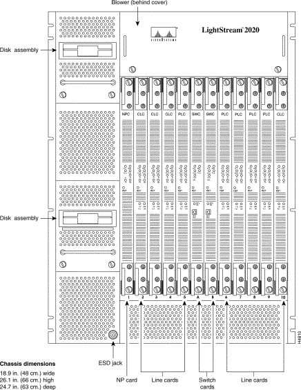
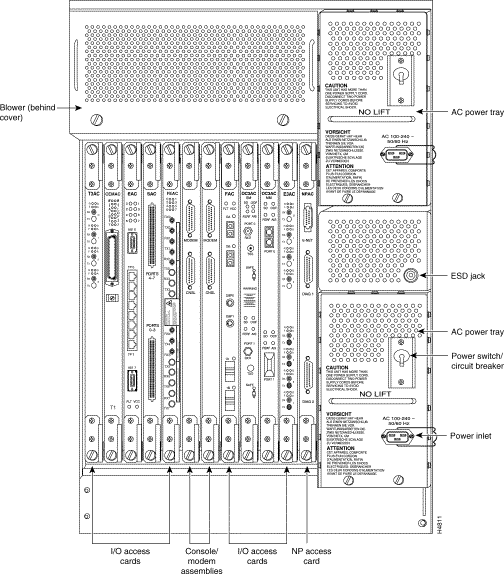
Figure 3-1 and Figure 3-2 show the locations of FRUs from the front and rear of the chassis.
When you remove a faulty component from an LS2020 system, you can return it for repair. Here is what to do:
Step 1 Contact the Cisco Systems Customer Response Center (CRC) to obtain a return material authorization (RMA) number and an address to which to ship the FRU. Here is how to reach the CRC:
Give the CRC the following information:
Step 2 Attach a tag to the FRU that lists the RMA number and describes the problem you experienced. Include instructions on how to reproduce the problem and a list of the diagnostic test numbers that the FRU failed.
Step 3 Pack the FRU securely and ship as directed.
Step 4 Record the replacement in your system's maintenance log.
The following is a complete list of tools and equipment you must have on hand when replacing FRUs:
This section explains how to remove and replace a switch card. Note that replacing the switch card in a nonredundant system causes the system to halt.
Step 1 In a redundant system, you can remove either switch card at any time. When you remove the primary switch card, the system cuts over to the secondary one without any loss of data.
To remove a switch card from a nonredundant system, first reboot the NP(s) to kill any UNIX processes. To do so, enter the following at the bash prompt:
LSnode:2# reboot -n
Wait for the menu of boot options to display before going to step 2.
Step 2 Unscrew the captive screws at the top and bottom of the card.
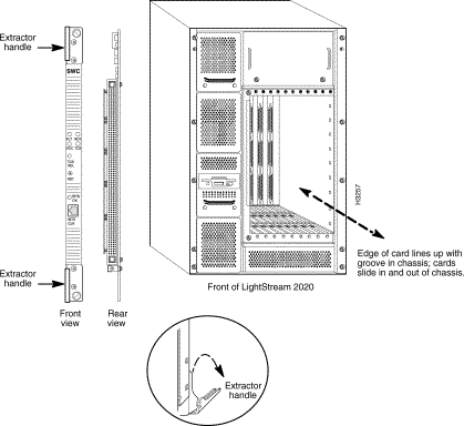
Step 3 Using the extractor handles, pull the card out of its slot. (See Figure 3-3.)
 | Warning 48V potential is present on the midplane at high levels. Be very careful when accessing this area; don't touch the midplane unnecessarily, and avoid contact with connectors and alignment pins. |
Step 1 Insert the new switch card into the slot, taking care to seat the card firmly in the midplane.
If a cable was detached from the BITS CLK port on the switch card, re-attach it.
Step 2 Lock down the extractor handles and tighten the screws that hold the card in place.
This section explains how to remove and replace an NP card. If you remove an NP card from a nonredundant system, traffic is interrupted until the card is replaced and rebooted. If you remove an NP from a redundant system, traffic is interrupted until the backup NP takes over.
Step 1 To remove an NP card on a redundant or nonredundant system, first reboot the NP card you want to remove to kill any UNIX processes. To do so, enter the following at the bash prompt:
LSnode:2# reboot -n
Wait for the menu of boot options to display before going to step 2.
Step 2 Unscrew the retaining screws at the top and bottom of the card.
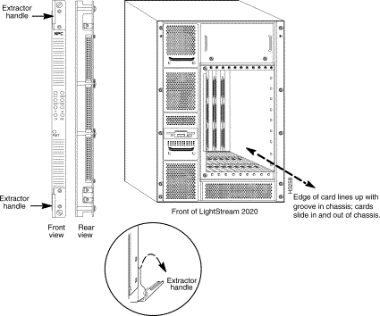
Step 3 Using the extractor handles, pull the card out of its slot. (See Figure 3-4.)
Step 1 Insert the new NP card into the slot, taking care to seat the card firmly in the midplane.
Step 2 Lock down the extractor handles and tighten the screws that hold the card in place.
This section explains how to remove and replace a line card.
 | Caution Do not swap one line card for another unless you are sure that the cards are of the same type. Most line cards can be configured as either edge or trunk cards. You cannot determine by looking at a card whether it is an edge or a trunk; check the configuration or use the show card command in CLI. |
Step 1 Unscrew the retaining screws at the top and bottom of the card.
Step 2 Using the extractor handles, pull the card out of its slot. (See Figure 3-5.)
Step 1 Insert the new line card into the slot, taking care to seat the card firmly in the midplane.
Step 2 Lock down the extractor handles and tighten the screws that hold the card in place.
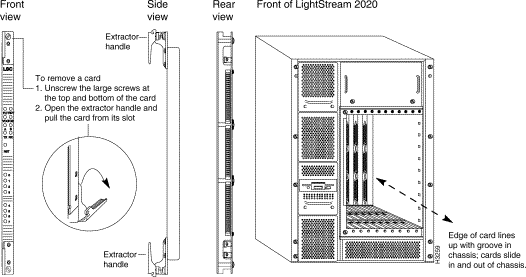
This section explains how to remove and replace an access card.
Step 1 Disconnect any cables attached to the access card. Label them so that you will be able to reconnect them to the new access card in exactly the same configuration.
Step 2 Unscrew the retaining screws at the top and bottom of the card.
Step 3 Using the extractor handles, pull the card out of its slot. (See Figure 3-6.)
 | Caution Before installing the new access card, ensure that the function card in that slot is turned off. (Check the VCC (power) LED on the card.) Connecting an access card to a powered-on function card can damage the access card. |
Step 1 Insert the new access card into the slot, taking care to seat the card firmly in the midplane.
Step 2 Lock down the extractor handles and tighten the screws that hold the card in place.
Step 3 Reconnect any cables that you disconnected when you removed the old access card.
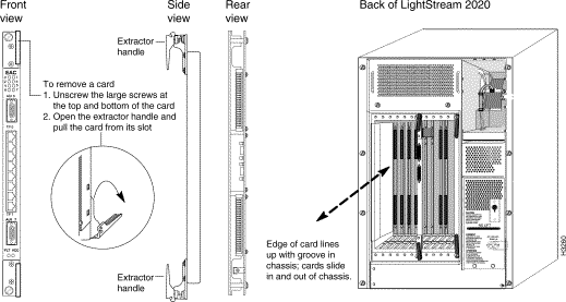
This section explains how to remove and replace a bulk power tray. Power trays are accessible from the rear of the chassis.
There are two types of AC power tray:
In addition, there is a DC power tray for DC-powered systems. This section gives separate removal procedures for each type of power tray, followed by a single replacement procedure for all three tray types.
Step 1 If this system has two power trays, skip to Step 2. If it has only one and is still operating, shut the system down before proceeding. (If you remove the only power tray in a system that is operating, the system loses power and ceases to operate.) See the section "Performing an Orderly Shutdown " later in this chapter for instructions.
Step 2 On the power tray you intend to replace, flip the circuit breaker to OFF and disconnect the power cord. (See Figure 3-7.)
Step 3 Unscrew the two captive screws that hold the power tray in place.
 | Warning When you remove the power tray, lethal AC voltage levels as well as 48 VDC are exposed. Touch only the front panel and the handle of the power tray. Do not insert tools or hands into the power supply tray or into the chassis. |
Step 4 Slowly slide the power tray out of the chassis.
Step 1 If this system has two power trays, skip to Step 2. If it has only one and is still operating, shut the system down before proceeding. (If you remove the only power tray in a system that is operating, the system loses power and ceases to operate.) See the section "Performing an Orderly Shutdown " later in this chapter for instructions.
Step 2 Unscrew the two captive screws that hold the power tray's cover in place. Remove the cover.
 | Warning When you remove the power tray cover, lethal AC voltage levels as well as 48 VDC are exposed. Touch only the front lip and the sides of the power tray. Do not insert tools or hands into the power supply tray or into the chassis. |
Step 3 Unscrew the two captive retaining screws that hold the power tray assembly in place. (See Figure 3-7.)
Step 4 Slowly slide the power tray out of the chassis.
Step 1 Shut the system down and turn off the power. See the section "Performing an Orderly Shutdown " later in this chapter for instructions.
Step 2 Disconnect the power wires and the alarm wires (if any) from the front of the power tray.
Step 3 Unscrew the two captive retaining screws that hold the power tray assembly in place. (See Figure 3-7.)
Step 4 Slowly slide the power tray out of the chassis.
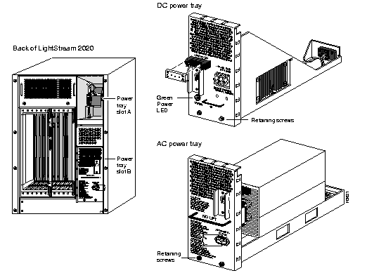
Step 1 Slide the new power tray into the housing in the chassis. Make sure that the power tray fits snugly.
Step 2 Tighten the two screws that hold the power tray assembly in place.
Step 3 Do one of the following:
Step 4 Turn on the power.
Step 5 Check the green LED on the power tray to ensure that the power is on. (On power trays with circuit breaker switches, the LED is just below the switch. On other trays, you should be able to see the LED through the cover.)
This section explains how to remove and replace a blower.
The blowers are at the top of the LS2020 chassis. One is accessible from the front and the other is accessible from the rear.
Step 1 Unscrew the two captive screws that hold the blower cover in place. Remove the cover.
Step 2 Unscrew the retaining screws (bottom front of the blower, shown in Figure 3-8) and slowly slide the blower out until its power LED goes out. When the impeller inside the blower stops spinning, remove the blower completely from the chassis.
 | Warning The impeller inside the blower box may still be turning when you loosen the retaining screws. Keep fingers, screwdrivers, and other objects away from the openings in the blower's housing. Do not remove the blower from the chassis until the impeller stops moving. |
Step 1 Slide the new blower into the chassis. Tighten the retaining screws (bottom front).
Step 2 Check the power LED on the front of the blower. It should be on if the system is powered up. (If the LED does not light up, the system may have a connector problem or a power problem.)
Step 3 Replace the cover and tighten the two screws that hold it in place.
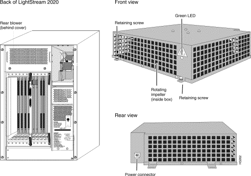
This section explains how to remove and replace a disk assembly.
The disk assembly is a single FRU consisting of a hard disk drive, a floppy disk drive, and an associated power supply. An LS2020 switch can have up to two disk assemblies. Each disk assembly is associated with a network processor card, and is connected to the network processor card by a ribbon cable attached to a male connector at the rear of the disk assembly slot.
Step 1 Unscrew the two screws that hold the disk assembly in place (Figure 3-9).
Step 2 Slowly slide the disk assembly out of the enclosure.
 | Warning When you remove the disk assembly, live power circuits are exposed. Touch only the handle on the front of the disk assembly until you can remove it from the chassis. Do not insert tools or hands into the disk assembly or into the chassis. |
Step 1 Slide the new disk assembly into the enclosure. When the connectors begin to engage, push slowly and gently to avoid damaging the pins.
Step 2 Tighten the two screws that hold the disk assembly in place.
The replacement disk assembly is shipped with the most recently released version of the LS2020 software. If you are not running the software version included with the disk assembly, you must install the version you are running. See the LightStream 2020 Network Operations Guide for instructions on installing software on the replacement disk.

This section tells you how to replace the 64-pin male DIN connector that is present at the back of each disk assembly slot in Release 2.0 and earlier hardware. Replace this connector if you notice that any of the pins are bent or broken.
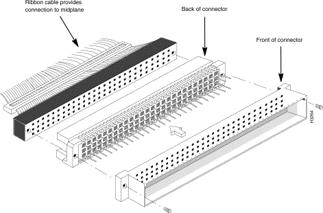
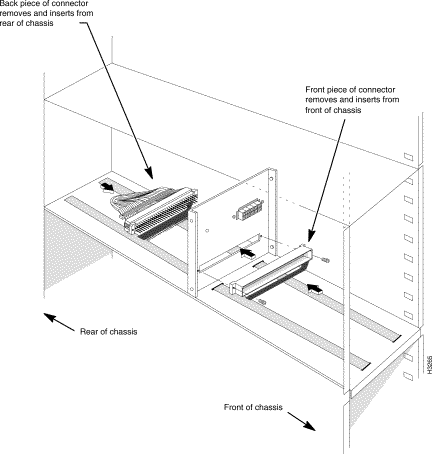
Have a second person on hand to help you with this procedure. The disk assembly connector is a two-piece "press fit" connector, shown in Figure 3-10. One piece inserts from the rear of the chassis and the other inserts from the front, making it difficult for one person to install a new connector alone.
Step 1 Perform an orderly shutdown of the system, as described in the section "Performing an Orderly Shutdown " later in this chapter.
Step 2 Remove the bulk power tray behind the connector that is being replaced. (See the preceding section, "Replacing a Power Tray ," if you need instructions on removing the power tray.)
Step 3 Following the instructions in the preceding section, "Replacing a Disk Assembly ," remove the disk assembly from the enclosure.
Step 4 From the rear of the chassis, unscrew the two Phillips-head screws that hold the SCSI ribbon cable in place at the rear of the disk assembly connector. Remove the ribbon cable. (Figure 3-10 shows how these pieces fit together.)
Step 5 Remove the two 3/16 lug screws from the rear of the connector. (These lugs held the screws removed in the previous step.)
Step 6 From the front of the chassis, remove the two Phillips-head screws from the front of the connector.
Step 7 Make a note of how the connector is keyed so that you can install the new one in the same manner.
Step 8 Disassemble the connector and remove it.
Step 1 The new connector consists of a back piece with pins and a front piece with holes. Have the person who is helping you hold the front piece in front of the hole in the sheet metal where the connector is being installed, as shown in Figure 3-11.
Step 2 From the rear of the chassis, insert the pins on the back of the connector through the hole in the sheet metal and through the front piece of the connector (which is held in place by the person helping you). When the two pieces of the connector begin to engage, push slowly and gently to avoid damaging the pins.
Step 3 Have your helper replace the two Phillips-head screws in the front of the connector.
Step 4 While your helper holds the two Phillips-head screws in place from the front, replace the two 3/16 lug screws in the rear of the connector.
Step 5 Replace the SCSI ribbon cable at the rear of the connector and secure it with the two Phillips-head screws that hold it in place.
Step 6 Carefully slide the disk assembly back into the enclosure. When the connectors begin to engage, push slowly and gently to avoid damaging the pins. Tighten the retaining screws that hold the disk assembly in place.
Step 7 Replace the power tray behind the connector that was replaced.
Step 8 Turn on the power and bring the system back up.
This section explains how to remove and replace the midplane. The first procedure tells you how to learn the chassis ID, which is stored in EEPROM on the midplane. You must find and record this number before removing the old midplane so you can store it in the EEPROM on the new midplane. (The EEPROMs are located on the back of the midplane near the middle of the top edge; the positions are labelled u1 and u2.)
This procedure takes approximately 2 hours.
The chassis ID should be recorded in each node's maintenance log. If the chassis ID isn't in the log, you can use this procedure to identify it, provided the EEPROMs on the midplane are healthy.
Step 1 Log into the system as root or fldsup.
Step 2 Run the sysver command at the bash prompt:
sysver -mp | more
Step 3 In the resulting display, locate the chassis ID. (If you have two switch cards, the chassis ID should be the same for both.) The chassis ID is displayed in hex and looks something like this example:
Record the pair of digits following each 0x. For the example above, you would record:
If you have changed the modem init string and modem password from the factory defaults, record them as well, as you will need to restore them later.
Step 1 Perform an orderly shutdown of the system, as described in the section "Performing an Orderly Shutdown " later in this chapter.
Step 2 Cut off the power to the system by detaching the power cord or turning off the power feed.
Step 3 Remove all the cards from the front of the chassis.
Step 4 From the rear of the chassis, unseat all the access cards and disconnect the console/modem assemblies. (It is not necessary to remove these items from the chassis.)
Step 5 From the rear of the chassis, remove the NP access card(s). Behind each NP access card, at the bottom of the slot, you will see a ribbon cable attached to the midplane. Disconnect each ribbon cable. (If you have two NPs--and thus two ribbon cables--you should label the cables so you can reconnect them properly later.)
Step 6 From the rear of the chassis, remove the lower power tray. (See the preceding section "Replacing a Power Tray " for instructions.)
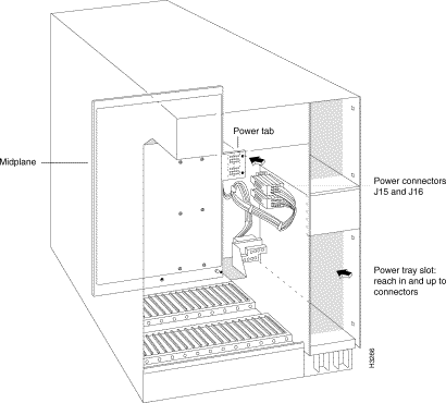
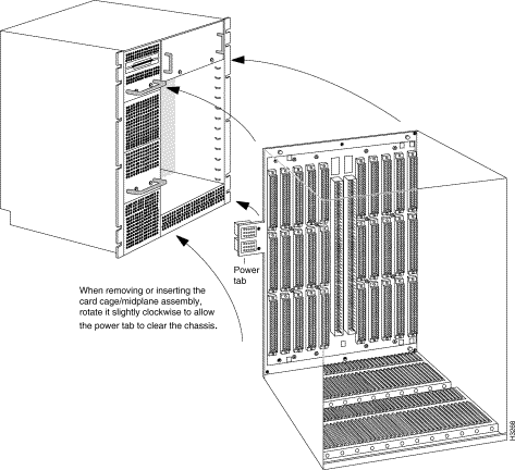
Step 7 Reach into the lower power tray slot and unplug the two power connectors (J15 and J16) from the midplane power tab, as shown in Figure 3-12. Note that Figure 3-12 does not show the internal bulkhead that separates the card cage on the left from the power tray slot.
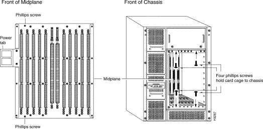
Step 8 From the front of the chassis, remove four #2 Phillips-head screws from the top and bottom of the frame surrounding the card cage. (See Figure 3-13.) The screws are located behind slots 3 and 7.
Step 9 Reach into the chassis and remove two no. 2 Phillips-head screws from the top and bottom corners of left side of the midplane. (Figure 3-13 shows the positions of the screws on the midplane.) The midplane is now disconnected from the chassis.
Step 10 Pull the card cage (with the midplane still attached at the rear) out of the chassis. As you remove this assembly, rotate it slightly clockwise to allow the power tab to clear the chassis. (See Figure 3-14.)
Step 11 To separate the midplane and card cage, remove all the Phillips-head screws from the back of the midplane.
Step 1 Screw the replacement midplane to the card cage.
Step 2 Slide the midplane-card cage assembly into the chassis, holding the assembly so that the midplane enters with the power tab foremost. When the power tab clears the corner of the disk housing, rotate the assembly counterclockwise until it fits snugly.
Step 3 Replace the two screws at the left corners of the midplane.
Step 4 Replace the four screws in the top and bottom of the frame surrounding the card cage.
Step 5 Reinsert the line cards, NPs, and switch cards into the chassis.
Step 6 From the rear of the chassis, reach into the lower power tray slot and reconnect plugs J15 and J16 to the midplane power tab. (The plugs are keyed to their sockets so that they cannot be connected incorrectly.)
Step 7 Replace the lower power tray.
Step 8 Locate the ribbon cable(s) behind the NP access card(s) and reconnect the cable(s) to the midplane. (There is one cable per NP.)
Step 9 Reconnect the console/modem assemblies and reseat the access cards; be sure to tighten all the retaining screws.
This procedure differs depending on whether your system has one switch card or two. If you have two switch cards, you need only enter two commands to program the two EEPROMs. If you have just one switch card, you must move the card from one switch slot to the other between commands. This is necessary because each midplane EEPROM is connected to one switch card slot, and you cannot program the EEPROM without a switch card in the slot. It is very important to have the same chassis ID on both midplane EEPROMs.
Step 1 Power up the system.
Step 2 Attach a terminal to the console port of the active switch card.
Step 3 The terminal connects to the TCS hub. At the prompt, enter the following command, replacing the placeholder at the end with your chassis ID, which you recorded at the beginning of this section:
set sa mid nodeaddr <chassisID>
Step 4 To verify that you entered the chassis ID in slot A correctly, enter the following command and check the chassis ID in the resulting display. (If you just set the chassis ID for slot B, begin this command with show sb instead of show sa.)
show sa mid nodeaddr
Step 5 If this system contains two switch cards, skip to step 7. If this system contains only one switch card, enter the following:
set sa power off
Step 6 Remove the switch card from the chassis and put it into the other switch card slot.
Step 7 From the rear of the chassis, move the console/modem assembly (keeping the console connection intact) to the other switch card slot. Note that when you return to the console, the TCS hub prompt changes from A to B (or from B to A, if you started with switch slot B). Press Return to display the new prompt.
Step 8 At the console, enter the following:
set sb mid nodeaddr <chassisID>
Step 9 To verify that you entered the chassis ID in slot B correctly, enter the following command and check the chassis ID in the resulting display. (If you just set the chassis ID for slot A, begin this command with show sa instead of show sb.)
show sb mid nodeaddr
Step 10 If the modem initialization string and modem password stored in midplane EEPROMs have not been changed from the factory defaults, skip to the next step. If the modem information has been changed, you must bring the new midplane up to date. Refer to the LightStream 2020 Network Operations Guide for instructions on programming the modem init string and password into the EEPROMs on the new midplane.
Step 11 To reset the system with the new EEPROM information, use the command shown below. Replace <slot#> with the slot number of the NP (1 or 2). If your system has two NPs, repeat this command for the second one.
reset <slot#>
Step 12 You can now bring the system up. To connect to the primary NP, use the command shown below. Replace <slot#> with the slot number of the active NP in the system (1 or 2).
connect <slot#>
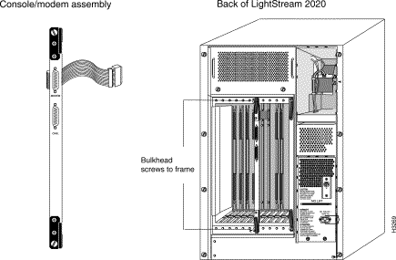
This section tells you how to remove and replace a console/modem assembly.
A console/modem assembly is located behind each switch card, at the rear of the chassis. The assembly consists of a bulkhead with console and modem ports mounted on it, with cables to connect to the midplane.
Step 1 Loosen the retaining screws at the top and bottom of the bulkhead.
Step 2 Pull the bulkhead away from the chassis (see Figure 3-15). You will see a ribbon cable that attaches the bulkhead to the midplane; disconnect it at the midplane end.
Step 1 Connect the new assembly's ribbon cable to the connector on the midplane.
Step 2 Line up the bulkhead against the card cage and tighten the top and bottom retaining screws.
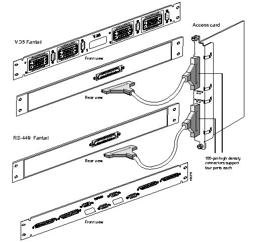
This section tells you how to remove and replace LS2020 fantails, which provide connectors for data cables. Figure 3-16 shows how fantails are connected to serial access cards and low-speed access cards. The X.21 fantail is not shown. It has two rear connectors, and both attach to the same access card.
Step 1 Disconnect any external data cables from the fantail. Label them with the numbers of the ports they were connected to so that you will be able to reattach them to the new fantail in exactly the same configuration.
Step 2 If you are replacing a fantail for a low-speed or E1 CEMAC module, disconnect the fantail cable (or cables) from the back of the fantail, leaving the cable(s) attached to the access card in the chassis.
Step 3 If you are replacing a fantail for a T3/E3 module, disconnect the cable harness from the access card, leaving it attached to the fantail.
Step 4 Using a 5/16-inch slotted-tip screwdriver, unscrew the mounting screws and remove the fantail from the equipment rack.
Step 1 If necessary, attach the four clip nuts provided with the new fantail to the holes in the equipment rack rails.
Step 2 Attach the fantail cable(s) to the back of the fantail or to the access card, as required.
Step 3 Using a 5/16-inch slotted-tip screwdriver and the mounting screws and washers provided, attach the fantail to the equipment rack.
Step 4 Label the fantail with the slot number or names of the line and access cards that it is connected to.
Step 5 Reconnect any data cables that were disconnected to remove the old fantail.
This section explains how to shut down an LS2020 switch gracefully, which involves rebooting the NPs. You may need to use this shutdown procedure before performing other procedures in this manual.
Two shut-down procedures are provided: the first is for switches with two NPs, the second for switches with one NP. Following the shut-down procedures are instructions for returning to service.
In a system with two NPs, you must reboot the backup NP before you reboot the active NP. (If you reboot the active NP first, the backup takes over and the system continues to operate.)
Step 1 Warn anyone who will be affected that you are taking the system out of service.
Step 2 Log in to the root account on the switch you want to shut down.
Step 3 To determine which NP is active (primary), start the CLI and enter the command show chassis general. Look for Slot of Primary NP in the resulting display. This is the NP you will reboot last.
Step 4 To log into the backup NP (the one whose slot number was not displayed in Step 3), do the following:
'. (back-quote followed by dot) to get a TCS hub prompt.
connect 2
Step 5 From the prompt, enter
reboot -n
Step 6 Enter '. to return to the TCS hub.
Step 7 At the TCS hub prompt, use connect <slot#> to connect to the active NP. The example below assumes that you are connecting to the NP in slot 1.
connect 1
Step 8 If necessary, enter quit to exit from CLI and get a bash prompt.
Step 9 From the prompt, enter
reboot -n
Step 10 You can now turn off the power.
Use this procedure to shut down a system with one NP, or to shut down one NP in a redundant system where you want the other NP to continue operating.
Step 1 Warn anyone who will be affected that you are taking the system out of service.
Step 2 Log in to the root account on the switch you want to shut down.
Step 3 From the prompt, enter
reboot -n
Step 4 You can now turn off the power.
If you turned off the power, you can return the system to service by turning the power on again.
If you did not turn off the power, use the command shown below at the TCS hub to bring the system back to service. Replace slot# with the slot number of the NP card (1 or 2):
reset <slot#>
You must issue the reset command to both NPs in a redundant system.
|
|