|
|

This procedure explains how to convert a LightStream 2020 chassis using a single power cord into a chassis that can use dual power cords. Because they enable you to connect a single chassis to two separate power sources, dual power cords minimize the effect of power failures on your network.
This procedure, which can be performed in the field, requires familiarity with LightStream 2020 (LS2020) hardware. It should be performed only by qualified support personnel or by customers with appropriate hardware knowledge.
To complete the conversion, you will do the following:
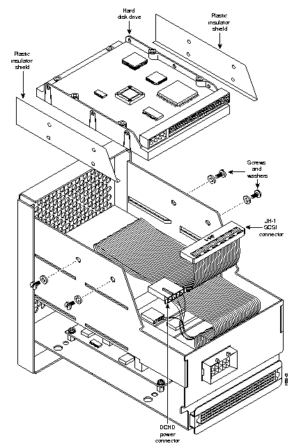
The upgrade kit includes sets of plastic screws, plastic washers, and plastic insulating shields that you might need to use when you move the hard disk drives from the old disk assemblies to the new disk assemblies (see Figure 4). The plastic "hardware" is designed to electrically isolate the hard disk drive from chassis ground. If your old disk assemblies contain plastic screws, washers, and shields like those in the kit, you can use either the old components or the new ones. However, if your hard disks are fastened to the disk assemblies with metal screws, discard the metal screws and use the plastic screws, washers, and plastic shields instead, as directed later in this document.
There are two dual power upgrade kits:
The kits include
In addition to the upgrade kit, you need
This section provides a procedure for shutting down an LS2020 switch with one NP, and a second procedure for shutting down a switch with two NPs. Perform the shutdown procedure that is appropriate for your system, then proceed to the next section, "Replacing the Power Trays."
To gracefully shut down an LS2020 system with one NP, perform the following steps:
Step 1 Connect a terminal to the console port at the rear of the chassis, dial in through the modem port, or telnet to the chassis. If you use telnet, skip to Step 3.
Step 2 At the TCS hub prompt, issue the command connect <slot#> to connect to the NP. (The example below assumes that you are connecting to the NP in slot 1.)
TCS hub<<A>> connect 1
Step 3 Log in to the NP as root.
Step 4 From the prompt, enter the following:
# reboot -n
Step 5 Turn off system power.
To gracefully shut down an LS2020 system with two NPs, perform the following steps:
Step 1 Connect a terminal to the console port at the rear of the chassis, dial in through the modem port, or telnet to the backup NP. If you use telnet, skip to Step 3.
Step 2 At the TCS hub prompt, issue the command connect <slot#> to connect to the backup NP. (The example below assumes that you are connecting to the NP in slot 2.)
TCS hub<<A>> connect 2
Step 3 Log in to the backup NP as root.
Step 4 From the prompt, enter the following:
# reboot -n
If you are using telnet, your connection breaks when the NP reboots. Telnet to the primary NP, log in as root, and skip to Step 8.
Step 5 If you are not using telnet, enter '. to return to the TCS hub prompt.
Step 6 At the prompt, issue the command connect <slot#> to connect to the primary (active) NP. (The example below assumes that you are connecting to the NP in slot 1.)
TCS hub<<A>> connect 1
Step 7 If necessary, enter the quit command to exit from the CLI and return to the LynxOS bash prompt.
Step 8 At the prompt, enter the following:
# reboot -n
Step 9 Turn off system power.

Step 1 Go to the rear of the chassis and attach your grounding wrist strap to the ESD jack at the right side of the rear panel.
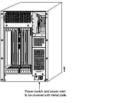
Step 2 Remove the power cord from the power inlet indicated in Figure 1.
Step 3 Use the phillips screwdriver to attach the metal cover plate (from the kit) over the main power switch and power inlet (see Figure 1).
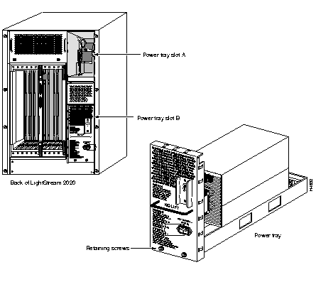
Step 4 Use the slot-tip screwdriver to loosen the retaining screws on the power tray (see Figure 2), then remove the power tray. If you have two power trays, remove the second tray as well.
Step 5 Install the new power trays, using the slot-tip screwdriver to tighten the retaining screws.
Step 6 Plug in the new power trays. Use the power cord you removed in Step 1 for one power tray and the new cord included in the upgrade kit for the other power tray.


Step 1 At the front of the chassis, use the slot-tip screwdriver to loosen the two screws that hold the disk assembly in place, and then remove the disk assembly from the chassis. (See Figure 3.)
Step 2 Place the disk assembly on the nonconducting mat to protect it from damaging electrostatic discharge.
Step 3 To remove the hard disk drive from the disk assembly, first disconnect two connectors, JH-1 and DCHD (see Figure 4). They are located at the rear of the assembly near the top.
Step 4 Use the slot-tip screwdriver to unscrew and remove the two screws on each side of the assembly (total 4 screws), as indicated in Figure 4. Each screw is accompanied by a washer. ® Note: In some assemblies, metal phillips screws hold the hard disk drive in place. If your assembly has metal screws, discard them after removal.
Step 5 Remove the hard disk drive and the plastic insulator shields on either side of it. (Some disk assemblies do not have plastic insulator shields.) Put the disk drive on the nonconducting mat.
Step 6 Before you install the hard disk drive in the new disk assembly, fold the ribbon cable into the area at the top of the assembly, leaving the connector hanging out at the rear of the assembly (see Figure 4). The object is to arrange the ribbon cable so that the hard disk can be installed on top of it, and then connected to it.
Step 7 Insert the plastic shields at either side of the disk assembly, lining up the holes in the shields with the screw holes in the sides of the disk assembly. (See Figure 4.)
Step 8 Insert the hard disk drive into the disk assembly, orienting the disk so that the two connectors face the rear of the assembly. (See Figure 4.) Line up the screw holes in the drive with the holes in the plastic shields and in the disk assembly.
Step 9 Thread each of the four plastic screws through a plastic washer and insert the screws into the holes in the sides of the disk assembly. Use the slot-tip screwdriver to tighten the screws. Be careful not to overtighten; plastic screws strip easily.
Step 10 Locate two connectors on the disk assembly: the connector labeled JH-1 on the SCSI ribbon cable referred to in Step 6, and a smaller, 3-wire power connector labelled DCHD. Both connectors are called out in Figure 4.
Step 11 With its JH-1 label facing up, attach the SCSI connector on the ribbon cable to the mating connector on the rear edge of the hard disk drive.
Step 12 With its DCHD label facing down, attach the 3-wire power connector to the mating connector on the rear edge of the hard disk drive.
Step 13 Insert the new disk assembly into the chassis.
 | Caution When the pins begin to engage, push the disk assembly slowly and firmly to avoid damaging the pins. |
Step 14 Tighten the two captive screws that fasten the disk assembly to the chassis.
Step 15 If your system has one NP, skip to Step 16 now. If your system has two NPs, repeat Step 1 through Step 14 for the second disk assembly.

Step 16 Switch the power on each power tray to on. The system should resume normal operation on its own. If it does not, or if you observe one of the indicators listed below, contact Cisco's Technical Assistance Center (TAC) at 800 553-2447, 408 526-7209, or tac@cisco.com.
|
|