|
|

Table Of Contents
Regulatory Compliance and Safety Information for the Catalyst 8500 and LightStream 1010 Series
Ensuring Overcurrent Protection
Installing and Servicing the System
Regulatory Standards Compliance
European Community, Switzerland, Norway, Iceland and Liechtenstein
EMC Environmental Conditions in the European Union
Obtaining Technical Assistance
Obtaining Additional Publications and Information
Regulatory Compliance and Safety Information for the Catalyst 8500 and LightStream 1010 Series
Read this document before installing or servicing the following Catalyst 8500 and LightStream 1010 series switches:
•
Catalyst 8540 MSR
•
•
•
•
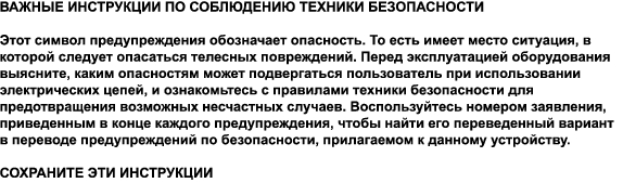
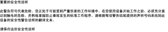
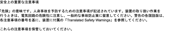
Note
Warning
Note
This document includes the following sections:
•
•
•
Site Preparation
This section describes the site requirements for installing the Catalyst 8500 MSR, Catalyst 8500 CSR, and LightSteam 1010 series switches. To ensure normal system operation, plan your site configuration and prepare your site before installation.
Follow these guidelines when choosing a site for installation:
•
•
•
Ensuring Overcurrent Protection
The system relies on the protective devices in the building installation for protection against short-circuit, overcurrent, and earth (grounding) fault. Ensure that the protective devices in the building installation are properly rated to protect the system, and that they comply with national and local codes.
Grounding the System
Follow these guidelines when grounding the system:
•
•
•
Creating a Safe Environment
Follow these guidelines to create a safe environment:
•
•
•
Rack-Mounting the System
A rack-mount kit and cable guides come with the system. The kit is not suitable for racks with obstructions (such as a power strip) that could impair access to system components. Allow sufficient clearance around the rack for system maintenance.
Ensuring Proper Airflow
Follow these guidelines to ensure proper airflow:
•
•
•
•
•
•
Stabilizing the System
Follow these guidelines to stabilize the system:
•
•
•
•
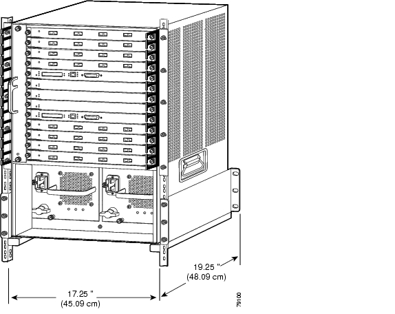
Figure 1 Catalyst 8540 Chassis Standard Equipment Rack Dimensions
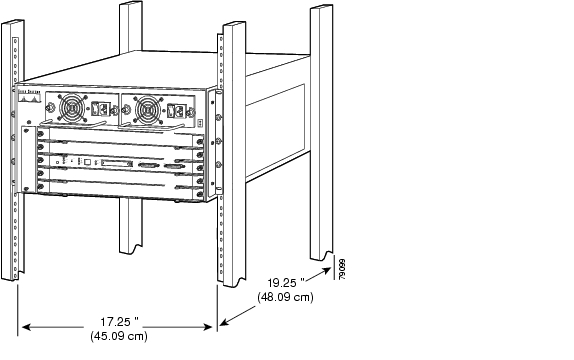
Figure 2 Catalyst 8510 and LightStream 1010 Chassis Standard Equipment Rack Dimensions
•
•
Lifting the System
Follow these guidelines when lifting the system:
•
•
•
•
•
Figure 3 shows the number of people needed to lift the system by weight.
Figure 3 Safely Lifting the System
Power Considerations
AC and DC power supplies, and an optional redundant (second) power supply, are available for most systems. Be careful when connecting systems to the supply circuit so that wiring is not overloaded.
Note
AC Power
The system is designed for connection to TN power systems. A TN power system is a power distribution system with one point connected directly to earth (ground). The exposed conductive parts of the installation are connected to that point by protective earth conductors.
Ensure that the plug-socket combination is accessible at all times, because it serves as the main disconnecting device.
DC Power
Follow these guidelines for DC power supplies:
•
•
•
•
•
•
Using Redundant Power
If your system includes an optional redundant (second) power supply, connect each of the two power supplies to different input power sources. Failure to do so makes the system susceptible to total power failure in the event that one of the power supplies fails.
Preventing ESD
Electrostatic discharge (ESD) damage occurs when electronic cards or components are mishandled and can result in complete or intermittent failures. Note the following guidelines before you install or service the system:
•
•
•
•
Note
Installing and Servicing the System
Follow these guidelines when installing and servicing the system:
•
•
–
–
–
•
•
•
•
Disconnecting Power
Follow these guidelines when disconnecting power:
•
•
•
•
•
Working with Lasers
The following laser safety standards classify the Catalyst 8500 MSR, Catalyst 8500 CSR, and LightSteam 1010 series switches:
•
•
Caution
Invisible laser radiation may be emitted from one end of the fiber or connector. Do not stare into the beam or view directly with optical instruments.
Preventing EMI
When you run wires for any significant distance in an electromagnetic field, electromagnetic interference (EMI) can occur between the field and the signals on the wires. Be aware of the following:
•
•
To predict and remedy strong EMI, consult RFI experts.
Covering Empty Slots
Ensure that all cards, faceplates, and covers are in place. Filler motherboards and filler modules and cover panels are used to:
•
•
•
•
Disposing of the System
Dispose of the system and its components (including batteries) as specified by all national laws and regulations.
Regulatory Standards Compliance
This section includes the regulatory compliance, safety, and EMC standards. It also lists the warnings applicable to different countries.
Table 1 lists the regulatory standards compliance specifications.
Table 2 lists the NEBS and ETSI specifications that the Catalyst 8500 MSR, Catalyst 8500 CSR, and LightSteam 1010 series switches are designed to meet.
Table 2 NEBS and ETSI Specifications
NEBS1
GR-63-Core NEBS Level 3 Requirements
GR-1089-Core NEBS Level 3 Requirements
ETSI2
ETS 300 019 Storage Class 1.1
ETS 300 019 Transportation Class 2.3
ETS 300 019 Stationary Use Class 3.1
1 NEBS = Network Equipment Building Systems
2 ETSI = European Telecommunication Standards Institute
FCC Part 68 Notice
The T1 IMA (Model C85MS-8T1-IMA) and CES T1 (Model WAI-T1C-4RJ48) interface modules used in the ATM switch router comply with Part 68 of the FCC rules. On the bottom of this equipment is a label that contains, among other information, the FCC registration number. If requested, this information must be provided to the telephone company.
This equipment cannot be used on telephone company-provided coin services. Connection to the Party Line Service is subject to state tariffs.
If this equipment causes harm to the telephone network, the telephone company notifies you in advance that temporary discontinuance of service might be required. If advance notice is not practical, the telephone company notifies you as soon as possible. Also, you are advised of your right to file a complaint with the FCC if you believe it is necessary.
The telephone company can make changes in its facilities, equipment, operations, or procedures that might affect the operation of the equipment. If this happens, the telephone company provides advance notice so you can make the necessary modifications to maintain uninterrupted service.
If you experience trouble with this equipment, please contact us for repair and warranty information. If the trouble is causing harm to the telephone network, the telephone company can request that you remove the equipment from the network until the problem is resolved.
We recommend that the customer install an AC surge arrestor in the AC outlet to which this device is connected. This is to avoid equipment damage caused by local lightning strikes and other electrical surges.
This equipment uses Uniform Service Order Code (USOC) jacks as listed in Table 3.
CS-03 Certification
The T1 IMA interface module is CS-03 certified. See Table 4 for CS-03 approval details for the equipment. Observe the following general information and safety precautions:
The industry Canada label identifies CS-03 certified equipment. This certification means that the equipment meets certain telecommunications network protection, operation, and safety requirements as described in the appropriate terminal equipment requirements document(s). The department does not guarantee the equipment will operate to the user's satisfaction.
Before installing the equipment, check that you have permission to connect it to the facilities of the local telecommunications company. The equipment must also be installed using an acceptable method of connection. The customer should be aware that compliance with the above conditions may not prevent degradation of service in some situations.
Repairs to certified equipment should be coordinated by a representative designated by the supplier. Any repairs or alterations made by the user to this equipment, or any equipment malfunctions, may cause the telecommunications company to request that the user disconnect the equipment.
Ensure that the electrical ground connections of the power utility, telephone lines, and internal metallic water pipe system, if present, are connected together. This precaution may be particularly important in rural areas.
Warning
JATE
The T1 IMA interface module meets the requirements of the Japan Approvals Institute for Telecommunications Equipment (JATE). Table 5 provides the JATE approval details for modules.
Table 5 JATE Approval
Nihon Cisco Systems
C85MS-8T1-IMA
D99-0386-JP
European Community, Switzerland, Norway, Iceland and Liechtenstein
Declaration of Conformity with Regard to the Directives 73/23/EEC and 89/336/EEC as amended by Directive 93/68/EEC
EMC Environmental Conditions in the European Union
This equipment is intended to operate under the following environmental conditions with respect to EMC:
•
•
•
In addition, if equipment is operated in a domestic environment, interference may occur.
FCC Class A warning
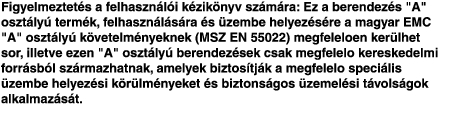
Warning
This equipment has been tested and found to comply with the limits for a Class A digital device, pursuant to Part 15 of the FCC Rules. These limits are designed to provide reasonable protection against harmful interference when the equipment is operated in a commercial environment. This equipment generates, uses, and can radiate radio frequency energy and, if not installed and used in accordance with the instruction manual, may cause harmful interference to radio communications. Operation of this equipment in a residential area is likely to cause harmful interference in which case users will be required to correct the interference at their own expense.
Canada Class A Warning
Warning
Cet appareil numηrique de la classe A est conforme α la norme NMB-003 du Canada.
CISPR 22 Class A Warning
This is a class A product. In a domestic environment this product may cause radio interference in which case the user may be required to take adequate measures.
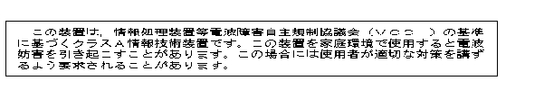
Japan VCCI Class A Warning
Warning
Taiwan (BSMI) Class A Warning
Warning
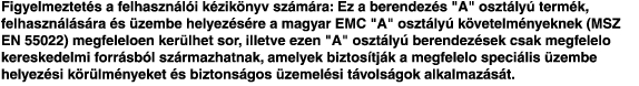
Class A Notice for Hungary
Korean Class A Warning
Translated Safety Warnings
This section includes translations in multiple languages of the warnings that may appear in the Catalyst 8500 MSR, Catalyst 8500 CSR, and LightSteam 1010 series switch product documents.
Warning Definition
Backplane Voltage
Ground Conductor
Restricted Area Warning
Qualified Personnel Warning
Warning Definition
Disconnect Device Warning
Laser Radiation Warning
Related Documentation
The following sections describe the documentation available for the Catalyst 8510 and the LightStream 1010 ATM switch. Typically, these documents consist of hardware installation guides, software installation guides, Cisco IOS configuration and command references, system error messages, and feature modules, which are updates to the Cisco IOS documentation. Documentation is available as printed manuals or electronic documents, except for feature modules, which are available online only.
The most up-to-date documentation can be found on the Web through Cisco.com and the Documentation CD-ROM. These electronic documents might contain updates and modifications made after the hard-copy documents were printed.
Table 6 lists hardware documentation you should reference before installing, cabling, or troubleshooting the Catalyst 8500 MSR, Catalyst 8500 CSR, and LightSteam 1010 series switches.
Table 6 Catalyst 8500 and LightStream 1010 Hardware Related Documentation
Hardware Installation Guides:
•
•
Provides information specific to installing and cabling the Catalyst 8500 series and LightStream 1010 ATM switch chassis.
DOC-786134=
DOC-785547=ATM and Layer 3 Module Installation Guide
Provides information about the hardware interface modules that can be installed in the ATM and Layer 3 systems.
DOC-781089=
1 You can order printed versions of documents with DOC numbers. Documents with OL numbers are available online only, but they can be printed from PDF.
This document should be used in conjunction with the documents listed in the following sections:
Platform Documents
The following is a list of the platform-specific documentation available for the Catalyst 8510 and the LightStream 1010 ATM switch:
•
•
Software Documents
The following is a list of the software documentation available for the Catalyst 8510 and the LightStream 1010 ATM switch:
•
•
•
•
•
Obtaining Documentation
Cisco provides several ways to obtain documentation, technical assistance, and other technical resources. These sections explain how to obtain technical information from Cisco Systems.
Cisco.com
You can access the most current Cisco documentation on the World Wide Web at this URL:
http://www.cisco.com/univercd/home/home.htm
You can access the Cisco website at this URL:
International Cisco websites can be accessed from this URL:
http://www.cisco.com/public/countries_languages.shtml
Documentation CD-ROM
Cisco documentation and additional literature are available in a Cisco Documentation CD-ROM package, which may have shipped with your product. The Documentation CD-ROM is updated regularly and may be more current than printed documentation. The CD-ROM package is available as a single unit or through an annual or quarterly subscription.
Registered Cisco.com users can order a single Documentation CD-ROM (product number DOC-CONDOCCD=) through the Cisco Ordering tool:
http://www.cisco.com/en/US/partner/ordering/ordering_place_order_ordering_tool_launch.html
All users can order annual or quarterly subscriptions through the online Subscription Store:
http://www.cisco.com/go/subscription
Ordering Documentation
You can find instructions for ordering documentation at this URL:
http://www.cisco.com/univercd/cc/td/doc/es_inpck/pdi.htm
You can order Cisco documentation in these ways:
•
http://www.cisco.com/en/US/partner/ordering/index.shtml
•
Documentation Feedback
You can submit comments electronically on Cisco.com. On the Cisco Documentation home page, click Feedback at the top of the page.
You can send your comments in e-mail to bug-doc@cisco.com.
You can submit comments by using the response card (if present) behind the front cover of your document or by writing to the following address:
Cisco Systems
Attn: Customer Document Ordering
170 West Tasman Drive
San Jose, CA 95134-9883We appreciate your comments.
Obtaining Technical Assistance
For all customers, partners, resellers, and distributors who hold valid Cisco service contracts, the Cisco Technical Assistance Center (TAC) provides 24-hour, award-winning technical support services, online and over the phone. Cisco.com features the Cisco TAC website as an online starting point for technical assistance.
Cisco TAC Website
The Cisco TAC website ( http://www.cisco.com/tac) provides online documents and tools for troubleshooting and resolving technical issues with Cisco products and technologies. The Cisco TAC website is available 24 hours a day, 365 days a year.
Accessing all the tools on the Cisco TAC website requires a Cisco.com user ID and password. If you have a valid service contract but do not have a login ID or password, register at this URL:
http://tools.cisco.com/RPF/register/register.do
Opening a TAC Case
The online TAC Case Open Tool ( http://www.cisco.com/tac/caseopen) is the fastest way to open P3 and P4 cases. (Your network is minimally impaired or you require product information). After you describe your situation, the TAC Case Open Tool automatically recommends resources for an immediate solution. If your issue is not resolved using these recommendations, your case will be assigned to a Cisco TAC engineer.
For P1 or P2 cases (your production network is down or severely degraded) or if you do not have Internet access, contact Cisco TAC by telephone. Cisco TAC engineers are assigned immediately to P1 and P2 cases to help keep your business operations running smoothly.
To open a case by telephone, use one of the following numbers:
Asia-Pacific: +61 2 8446 7411 (Australia: 1 800 805 227)
EMEA: +32 2 704 55 55
USA: 1 800 553-2447For a complete listing of Cisco TAC contacts, go to this URL:
http://www.cisco.com/warp/public/687/Directory/DirTAC.shtml
TAC Case Priority Definitions
To ensure that all cases are reported in a standard format, Cisco has established case priority definitions.
Priority 1 (P1)—Your network is "down" or there is a critical impact to your business operations. You and Cisco will commit all necessary resources around the clock to resolve the situation.
Priority 2 (P2)—Operation of an existing network is severely degraded, or significant aspects of your business operation are negatively affected by inadequate performance of Cisco products. You and Cisco will commit full-time resources during normal business hours to resolve the situation.
Priority 3 (P3)—Operational performance of your network is impaired, but most business operations remain functional. You and Cisco will commit resources during normal business hours to restore service to satisfactory levels.
Priority 4 (P4)—You require information or assistance with Cisco product capabilities, installation, or configuration. There is little or no effect on your business operations.
Obtaining Additional Publications and Information
Information about Cisco products, technologies, and network solutions is available from various online and printed sources.
•
http://www.cisco.com/en/US/products/products_catalog_links_launch.html
•
•
http://www.cisco.com/go/packet
•
http://www.cisco.com/go/iqmagazine
•
http://www.cisco.com/en/US/about/ac123/ac147/about_cisco_the_internet_protocol_journal.html
•
http://www.cisco.com/en/US/learning/index.html
This document is to be used in conjunction with the documents listed in the "Related Documentation" section.
CCIP, CCSP, the Cisco Arrow logo, the Cisco Powered Network mark, Cisco Unity, Follow Me Browsing, FormShare, and StackWise are trademarks of Cisco Systems, Inc.; Changing the Way We Work, Live, Play, and Learn, and iQuick Study are service marks of Cisco Systems, Inc.; and Aironet, ASIST, BPX, Catalyst, CCDA, CCDP, CCIE, CCNA, CCNP, Cisco, the Cisco Certified Internetwork Expert logo, Cisco IOS, the Cisco IOS logo, Cisco Press, Cisco Systems, Cisco Systems Capital, the Cisco Systems logo, Empowering the Internet Generation, Enterprise/Solver, EtherChannel, EtherSwitch, Fast Step, GigaStack, Internet Quotient, IOS, IP/TV, iQ Expertise, the iQ logo, iQ Net Readiness Scorecard, LightStream, MGX, MICA, the Networkers logo, Networking Academy, Network Registrar, Packet, PIX, Post-Routing, Pre-Routing, RateMUX, Registrar, ScriptShare, SlideCast, SMARTnet, StrataView Plus, Stratm, SwitchProbe, TeleRouter, The Fastest Way to Increase Your Internet Quotient, TransPath, and VCO are registered trademarks of Cisco Systems, Inc. and/or its affiliates in the U.S. and certain other countries.
All other trademarks mentioned in this document or Web site are the property of their respective owners. The use of the word partner does not imply a partnership relationship between Cisco and any other company. (0304R)
Copyright © 2003 Cisco Systems, Inc. All rights reserved.
![]()
![]()
![]()
![]()
![]()
![]()
![]()
![]()
Posted: Mon Sep 13 10:49:19 PDT 2004
All contents are Copyright © 1992--2004 Cisco Systems, Inc. All rights reserved.
Important Notices and Privacy Statement.