|
|

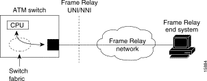
This chapter describes Frame Relay to ATM interworking and the required steps to configure the channelized Frame Relay port adapters in the Catalyst 8510 MSR and LightStream 1010 ATM switch routers. These port adapters facilitate interworking between a Frame Relay network, an ATM network, and network users. Existing Frame Relay users can also migrate to higher bandwidth ATM using channelized Frame Relay port adapters. Additionally, these port adapters extend the ATM network across a wide area over a frame-based serial line or intervening Frame Relay WAN.
Note This chapter provides advanced configuration instructions for the Catalyst 8540 MSR, Catalyst 8510 MSR, and LightStream 1010 ATM switch routers. For an overview of Frame Relay to ATM interworking, refer to the Guide to ATM Technology. For complete descriptions of the commands mentioned in this chapter, refer to the ATM Switch Router Command Reference publication.
For a more information on how to configure your Frame Relay specific network equipment, refer to the Cisco IOS 11.3 publications on the Documentation CD-ROM.
The chapter includes the following sections:
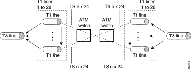
The channelized DS3 (CDS3) Frame Relay port adapter provides one physical port (45 Mbps). Each DS3 interface consists of 28 T1 lines multiplexed through a single T3 trunk. Each T1 line operates at 1.544 Mbps, which equates to 24 time slots (DS0 channels). A DS0 time slot provides 56 or 64 Kbps of usable bandwidth. You can combine one or more DS0 time slots into a channel group to form a serial interface. A channel group provides n x 56 or 64 Kbps of usable bandwidth, where n is the number of time slots, from 1 to 24. You can configure a maximum of 127 serial interfaces, or channel groups, per port adapter.
Figure 19-1 illustrates how a T3 trunk demultiplexes into 28 T1 lines that provide single or multiple time slots mapped across the ATM network. These time slots are then multiplexed to form an outgoing T3 bit stream.
In order to configure the CDS3 Frame Relay port adapter physical interface you need the following information:
The following defaults are assigned to all CDS3 Frame Relay port adapter interfaces:
The following defaults are assigned to all T1 lines on the CDS3 Frame Relay port adapter:
To manually change any of your default configuration values, perform the following steps, beginning in global configuration mode:
| 1MDL messages are only supported when framing on the CDS3 Frame Relay port adapter is set for c-bit parity. |
The following example shows how to change the cable length configuration to 300 using the cablelength command.
When using the cable length option, note that user-specified T3 cable lengths are structured into ranges as follows: 0 to 224 and 225 to 450. If you enter a cable length value that falls into one of these ranges, the range for that value is used.
For example, if you enter 150 feet, the 0 to 224 range is used. If you later change the cable length to 200 feet, there is no change because 200 is within the 0 to 224 range. However, if you change the cable length to 250, the 225 to 450 range is used. The actual number you enter is stored in the configuration file.
To configure the T1 lines, perform the following steps, beginning in global configuration mode:
| Command | Purpose | |
|---|---|---|
Specifies the controller interface port and enters controller configuration mode. |
||
| 2 | ||
| 3 |
A channel group, also referred to as a serial interface, is configured on a T1 line by associating time slots to it. The channel group can have from 1 to 24 time slots (DS0s). The transmission rate or bandwidth of the channel group is calculated by multiplying the number of time slots times 56 Kbps or 64 Kbps.
Note A time slot can be part of only one channel group. Additionally, all time slots within a channel group must be on the same T1.
To configure the channel group on a T1, perform the following steps, beginning in global configuration mode:
The following example shows how to configure a channel group (with identifier 5), assigning time slots 1 through 5 on T1 line 1 using the channel-group command.
To display the controller configuration, use one of the following EXEC commands:
The following example displays the configuration, status, and statistics of T1 line number 1 on controller 0/1/0:
This section describes two ways to delete a channel group on the CDS3 after it has been configured.
If you want to delete individual channel groups without shutting down the controller, use method one.
If you want to delete several channels groups on a controller, use method two. However, if you use method two, you must first shut down the controller, which shuts down all channel groups on the controller.
Perform the following steps, beginning in global configuration mode:
| Step | Command | Purpose |
|---|---|---|
| 1. | Selects the Frame Relay serial port and channel group number to be deleted. |
|
| 2. | ||
| 3. | ||
| 4. | Selects the controller interface port and enters controller configuration mode. |
|
| 5. |
Perform the following steps, beginning in global configuration mode:
| Step | Command | Purpose |
|---|---|---|
| 1. | Selects the controller interface port and enters controller configuration mode. |
|
| 2. | ||
| 3. | ||
| 4. |
The following example shuts down the serial interface and deletes channel group 1:
The following example shuts down the controller T3, deletes channel group 1, and then reenables the controller T3:
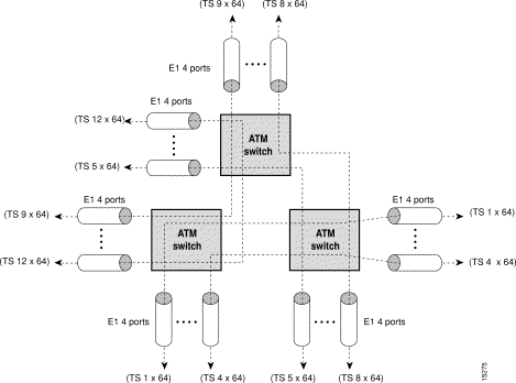
The channelized E1 (CE1) Frame Relay port adapter provides four physical ports. Each port supports up to 31 E1 serial interfaces, also referred to as channel groups, totalling 124 serial interfaces per port adapter. The E1 line operates at 2.048 Mbps, which is equivalent to 31 time slots (DS0 channels). The E1 time slot provides usable bandwidth of n x 64 kbps, where n is the time slot from 1 to 31.
Figure 19-2 illustrates how an E1 trunk (with four ports) provides single or multiple time slots mapped across the ATM network. Each time slot represents a single n x 64 circuit that transmits data at a rate of 64 Kbps. Multiple n x 64 circuits can be connected to a single port, using separate time slots.
The following defaults are assigned to all CE1 Frame Relay port adapter interfaces:
If your CE1 Frame Relay port adapter needs to be configured, you must have the following information:
To manually change any of your default configuration values, perform the following steps, beginning in global configuration mode:
| Step | Command | Purpose |
|---|---|---|
| 1 | Specifies the controller interface port and enters controller configuration mode. |
|
| 2 | clock source {free-running | loop-timed | reference | network-derived} |
|
| 3 |
The following example shows how to change the clock source to free-running using the clock source command.
A channel group, also referred to as a serial interface, is configured on an E1 line by associating time slots to it. The channel group can have from 1 to 31 time slots (DS0s). The transmission rate or bandwidth of the channel group is calculated by multiplying the number of time slots times 64 Kbps.
To configure the channel group, perform the following steps, beginning in global configuration mode:
The following example shows how to configure time slots 1 through 5 and 20 through 23 on E1 channel group 5 using the channel-group command.
To display your controller configuration, use the following EXEC command:
| Command | Purpose |
|---|---|
The configuration for controller E1 is displayed in the following example:
You must follow the required steps to enable Frame Relay to ATM interworking on your ATM switch router. In addition, you can customize Frame Relay to ATM for your particular network needs and monitor Frame Relay-to-ATM connections. The following sections outline these tasks:
For information on how to customize your Frame Relay-to-ATM connections, see the "Configuring LMI" section and the "Configuring Frame Relay to ATM Resource Management" section in this chapter.
To set Frame Relay encapsulation on the serial interface, perform the following steps, beginning in global configuration mode:
| Step | Command | Purpose |
|---|---|---|
| 1 | ||
| 2 |
Frame Relay supports encapsulation of all supported protocols in conformance with RFC 1490, allowing interoperability between multiple vendors.
To display Frame Relay encapsulation, use the following user EXEC command:
The following example displays the Frame Relay encapsulation configuration on serial interface 0/1/0:5
To configure an interface as a data communications equipment (DCE) or Network-to-Network Interface (NNI) type, perform the following steps, beginning in global configuration mode:
| Step | Command | Purpose |
|---|---|---|
| 1 | ||
| 2 |
The following example shows how to configure Frame Relay interface type NNI for serial interface 0/1/0:5:
To display the Frame Relay interface configuration, use the following EXEC command:
The Frame Relay configuration is displayed in the following example:
Three industry-accepted standards are supported for addressing the Local Management Interface (LMI), including the Cisco specification. By default, the Cisco ILMI option is active on your Frame Relay interface.
To manually set an LMI type on your Frame Relay port adapter, perform the following steps, beginning in global configuration mode:
| Step | Command | Purpose |
|---|---|---|
| 1 | ||
| 2 | ||
| 3 | ||
| 4 |
The following example changes the LMI type to ansi on serial interface 1/1/0:1:
To display the LMI type configuration, perform the following task in user EXEC mode:
| Command | Purpose |
|---|---|
The following example displays the LMI type configuration of a Frame Relay port adapter:
A keepalive interval must be set to configure the LMI. By default, this interval is 10 seconds and, per the LMI protocol, must be set as a positive integer that is less than the lmi-t392dce interval set on the interface of the neighboring switch. To set the keepalive interval, perform the following steps, beginning in global configuration mode:
| Step | Command | Purpose |
|---|---|---|
| 1 | ||
| 2 |
The following example configures the LMI keepalive interval to 30 seconds:
To display the LMI keepalive interval, perform the following task in user EXEC mode:
| Command | Purpose |
|---|---|
The following example displays the LMI keepalive interval of a Frame Relay port adapter:
You can set various optional counters, intervals, and thresholds to fine-tune the operation of your LMI on your Frame Relay devices. Set these attributes by performing one or more of the following steps, beginning in global configuration mode:
| Step | Command | Purpose |
|---|---|---|
| 1 | ||
| 2 | ||
| 3 | ||
| 4 | ||
| 5 | ||
| 6 | ||
| 7 | Configures the polling verification timer on a DCE or NNI interface. |
The following example shows how to change the default polling verification timer on a Frame Relay interface to 20 seconds using the frame-relay lmi-t392dce command.
To display information about a serial interface, perform the following task in user EXEC mode:
The following example displays serial interface configuration information for an interface with Cisco LMI enabled:
To display statistics about the LMI, perform the following task in user EXEC mode:
| Command | Purpose |
|---|---|
The following example displays the LMI statistics of a Frame Relay port adapter with an NNI interface:
This section describes the following resource management tasks specifically for your Frame Relay to ATM interworking network needs:
For information about how to configure your ATM Connection Traffic Table rows, see the "Configuring the Connection Traffic Table" section in the "Configuring Resource Management" chapter.
A row in the Frame Relay-to-ATM Connection Traffic Table (CTT) must be created for each unique combination of Frame Relay traffic parameters. All Frame Relay to ATM interworking virtual connections then provide traffic parameters for each row in the table per flow (receive and transmit). Multiple virtual connections can refer to the same traffic table row.
The Frame Relay traffic parameters (specified in the command used to create the row) are converted into equivalent ATM traffic parameters. Both parameters are stored internally and used for interworking virtual connections.
The formula used for Frame Relay to ATM traffic conversions are specified in the B-ICI specification, V2.0. Use a frame size (n) of 250 bytes and a header size of 2 bytes.
Table 19-1 Frame Relay to ATM Traffic Conversion
(Committed Burst Size2 /8 * (1/(1-Committed |
| 1In bits per second.
2In bits. |
PVC connection traffic rows, or stable rows, are used to specify traffic parameters for PVCs.
SVC connection traffic rows, or transient rows, are used by the signalling software to obtain traffic parameters for soft SVCs.
Note SVC connection traffic rows cannot be deleted from the CLI or SNMP. They are automatically deleted when the connection is removed.
To make the CTT management software more efficient, the CTT row-index space is split into space allocated by the CLI/SNMP and signalling. See Table 19-2.
Table 19-2 CTT Row-Index Allocation
| Allocated By | Row-Index Range |
|---|---|
Table 19-3 describes the predefined row:
Table 19-3 Default Frame Relay to ATM Connection Traffic Table Row
| CTT Row-Index | CIR (bits/s) | Bc (bits) | Be (bits) | PIR (bits/s) | Service Category |
ATM Row-Index |
|---|---|---|---|---|---|---|
To create a Frame Relay-to-ATM CTT row, perform the following task in global configuration mode:
| Command | Purpose |
|---|---|
frame-relay connection-traffic-table-row [index row-index] cir-value bc-value pir-value be-value {abr | vbr-nrt | ubr} [atm-row-index] |
If you do not specify an index row number, the system software determines if one is free. The index row number is then displayed in the allocated index field if the command is successful.
If the ATM row index is not specified, system software tries to use the same row index used by Frame Relay. If not possible, a free ATM row index is used.
The following example shows how to configure a Frame Relay-to-ATM CTT row with non-real-time variable bit rate (VBR-NRT) service category, committed information rate of 64000 bits per second, a peak information rate of 1536000 bits per second, and a committed burst size of 8192 bits per second:
To display the Frame Relay-to-ATM CTT configuration, use the following EXEC command:
The following example shows how to display the Frame Relay-to-ATM CTT configuration table:
The following resource management tasks configure queue thresholds, committed burst size, and service overflow on Frame Relay interfaces. To change any of these interface parameters, perform the following steps, in interface configuration mode:
Note Steps 1, 2, 4, and 5 affect existing and future connections on the Frame Relay interface, but Step 3 affects only future connections.
To display your Frame Relay interface resource configuration, use the following EXEC command:
The resource information for Frame Relay serial interface 0/1/0:5 is displayed in the following example:
This section describes how to configure virtual connections (VCs) for Frame Relay to ATM interworking and Frame Relay-to-Frame Relay switching.
The tasks to configure virtual connections are described in the following sections:
Perform the following tasks in a prescribed order before configuring a Frame Relay to ATM interworking PVC, soft PVC, or a Frame Relay-to-Frame Relay PVC:
Step 2 Configure the T1 channel or E1 interface and channel group on the Frame Relay port adapter.
Step 3 Configure Frame Relay encapsulation and Frame Relay LMI on the serial port corresponding to the channel group configured in Step 2.
Step 4 Configure Frame Relay resource management tasks including Frame Relay connection traffic table rows.
Step 5 Configure Frame Relay to ATM interworking VC tasks.
The characteristics of the Frame Relay to ATM interworking VC, established when the VC is created, include the following:
These switching features can be turned off with the interface configuration commands.
Note For information about ATM VCCs, refer to the "Configuring Virtual Connections" chapter in this publication.
Table 19-4 lists the types of supported virtual connections.
Table 19-4 Supported Frame Relay to ATM Virtual Connection Types
| Connection | Point-to-Point | Point-to-Multipoint | Transit | Terminate |
|---|---|---|---|---|
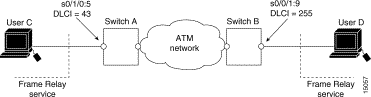
This section describes configuring Frame Relay to ATM network interworking PVCs. This type of connection establishes a bidirectional facility that transfers Frame Relay traffic between two Frame Relay users through an ATM network.
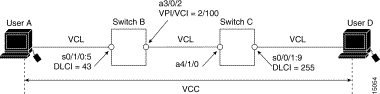
Figure 19-3 shows an example of a Frame Relay to ATM network interworking PVC between Frame Relay User A and ATM User D through an ATM network.
To configure a Frame Relay to ATM network interworking PVC, perform the following steps, beginning in global configuration mode:
| 1The serial interface is created with the channel-group command and configured using the encapsulation frame-relay ietf command. cgn is the channel group number of a channel group configured using the channel-group command.
2The dlci value appears in the Conn-Id and X-Conn-Id columns of the show vc command. |
Note The row index for rx-cttr and tx-cttr must be configured before using this optional parameter. See the section "Configuring the Connection Traffic Table" in the chapter "Configuring Resource Management."
The following example shows how to configure the internal cross-connect Frame Relay to ATM network interworking PVC on Switch B between serial interface 0/1/0:5, DLCI = 43 and ATM interface 3/0/2, VPI = 2, VCI = 100 (see Figure 19-3):
The following example shows how to configure the internal cross-connect PVC on Switch C between serial interface 0/0/1:9, DLCI = 255 and ATM interface 4/1/0, VPI = 2, VCI = 100:
Note The Frame Relay to ATM network interworking PVC must be configured from the serial interface and cross-connected to the ATM interface.
To display the network interworking configuration, use the following EXEC command:
| Command | Purpose |
|---|---|
show vc [interface {atm card/subcard/port [vpi vci] | serial card/subcard/port:cgn [dlci]}] |
The following example displays the Switch B PVC configuration for serial interface 0/1/0:5:
The following example displays the configuration of Switch B PVC on serial interface 0/1/0:5,
DLCI = 43:
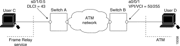
This section describes configuring Frame Relay to ATM service interworking PVCs. A Frame Relay to ATM service interworking PVC is established as a bidirectional facility to transfer Frame Relay to ATM traffic between a Frame Relay user and an ATM user. The upper user protocol encapsulation (FRF.3, RFC 1483, RFC 1490, RFC 1577) mapping can be enabled with the translation option of the frame-relay pvc command.
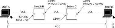
Figure 19-4 shows an example of a Frame Relay to ATM service interworking PVC between Frame Relay User A and ATM User D through an ATM network.
To configure a Frame Relay to ATM service interworking PVC, perform the following steps beginning in global configuration mode:
| 1The any-vci option is only available on interface atm0. See note below. |
Note With this release of the software, addressing the interface on the route processor has changed. The ATM interface is now called atm0, and the Ethernet interface is now called ethernet0. Old formats (atm 2/0/0 and ethernet 2/0/0) are still supported.
Note The row index for rx-cttr and tx-cttr must be configured before using this optional parameter. See the section "Configuring the Connection Traffic Table" in the chapter "Configuring Resource Management."
The following example shows how to configure the internal cross-connect PVC on Switch B between serial interface 0/1/0:5, DLCI = 43 and ATM interface 3/0/2, VPI = 2, VCI = 100 (with the translation option):
The following example shows how to configure the internal cross-connect PVC on Switch C between ATM interface 4/1/0, VPI = 2, VCI = 100 and ATM interface 0/0/1, VPI 50, VCI = 255:
Each subsequent VC cross connection and link must be configured until the VC is terminated to create the entire PVC.
Note The Frame Relay to ATM service interworking PVC must be configured from the serial interface and then cross-connected to the ATM interface.
To display the service interworking PVC configuration, use the following EXEC commands:
| Command | Purpose |
|---|---|
show vc [interface {atm card/subcard/port [vpi vci] | serial card/subcard/port:cgn [dlci]}] |
This section describes configuring terminating Frame Relay to ATM service interworking PVCs. This type of terminating connection provides the connection from IP over Frame Relay to the ATM switch router used for IP over ATM and network management.
Figure 19-5 shows an example of transmit and terminating connections.
Terminating connections are configured using the frame-relay pvc command; however, all switch terminating connections use atm0 to connect to the ATM switch route processor.
To configure terminating Frame Relay to ATM service interworking PVC connections, perform the following steps, beginning in global configuration mode:
| 1The any-vci option is only available on interface atm0. |
The following example shows how to configure the internal cross-connect PVC on Switch B between serial interface 0/1/0:5, DLCI = 50 and the terminating connection on ATM interface 0, VPI = 0 and an unspecified VCI:
Note The Frame Relay to ATM service interworking PVC must be configured from the serial interface and then cross connected to the ATM interface.
To display the service interworking PVC configuration, use the following EXEC commands:
| Command | Purpose |
|---|---|
show vc [interface {atm card/subcard/port [vpi vci] | serial card/subcard/port:cgn [dlci]}] |
Note See the section "Displaying Frame Relay to ATM Network Interworking PVCs" for examples of the show vc command.
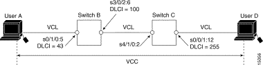
This section describes configuring internal cross-connect Frame Relay-to-Frame Relay transit PVCs. This type of PVC is used to establish a bidirectional facility to transfer Frame Relay traffic between two Frame Relay users. Figure 19-6 shows a Frame Relay transit PVC between Frame Relay Users A and D.
To configure a Frame Relay transit PVC, perform the following steps, beginning in global configuration mode:
| Step | Command | Purpose |
|---|---|---|
| 1 | ||
| 2 | frame-relay pvc dlci [upc {pass | drop}] [rx-cttr index] [tx-cttr index] interface serial card/subcard/port:cgn dlci dlci [upc {pass | drop}] [rx-cttr index] [tx-cttr index] |
The following example shows how to configure the internal cross-connect Frame Relay PVC on Switch B between serial interface 0/1/0:5, DLCI = 43 and serial interface 3/0/2:6, DLCI = 100:
The following example shows how to configure the internal cross-connect Frame Relay on Switch C between serial interface 4/1/0:2, DLCI = 100 and serial interface 0/0/1:12, DLCI = 255:
Each subsequent VC cross-connection and link must be configured until the VC is terminated to create the entire VCC.
To display Frame Relay transit PVCs, use the show interfaces and show vc commands.
This section describes configuring Frame Relay to ATM interworking soft PVC connections.
You can configure the following soft PVC connections:
These guidelines are appropriate for both network and service interworking soft PVC connections.
Perform the following steps and refer to Figure 19-7:
Step 2 Determine the source (active) side of the soft PVC.
Step 3 Determine an available DLCI for value dlci_a on the source end of the soft PVC.
Step 4 Determine the destination (passive) side of the soft PVC.
Step 5 Determine the ATM address of the destination side of the soft PVC. Use the show atm address command on the destination switch.
Step 6 If the destination side of the soft PVC is a Frame Relay interface, choose an available DLCI value. Use the show vc interface serial command.
If the destination side of the soft PVC is an ATM interface, choose an available VPI/VCI value.
Step 7 Choose the interworking function type, and the relevant interworking parameters (for example, de-bit/clp-bit mapping options).
Note If the soft PVC terminates on a Frame Relay interface, the soft PVC can only be configured as a network interworking connection. If the soft PVC terminates on an ATM interface, the soft PVC can be configured either as a network interworking connection or a service interworking connection.
Step 8 Configure the Frame Relay interworking soft PVC on the source side. See the following sections for configuration steps and examples.
This section describes how to configure a Frame Relay-to-Frame Relay network interworking soft PVC terminating on two Frame Relay interfaces. Figure 19-7 shows a Frame Relay-to-Frame Relay network interworking soft PVC between Switch A and Switch B.
To configure a Frame Relay-to-Frame Relay network interworking soft PVC, perform the following steps, beginning in EXEC mode:
The previous configuration steps are illustrated in the following section.
Note The row index for rx-cttr and tx-cttr must be configured before using this optional parameter. See the section "Configuring the Connection Traffic Table" in the chapter "Configuring Resource Management."
This section provides an example of a Frame Relay-to-Frame Relay network interworking soft PVC configured between Switch A and Switch B and shown in Figure 19-7. The source (active) side is serial interface 0/1/0:5 on Switch A.
Step 2 The destination (passive) side is a Frame Relay serial interface 0/0/1:9 on Switch B.
Step 3 The ATM address for the destination serial interface 0/0/1:9 on Switch B is 47.0091.8100.0000.00e0.1e79.8803.4000.0c81.8010.00.
Step 4 DLCI 255 is available on serial interface 0/0/1:9 Switch B.
Step 5 Configure the network interworking soft PVC from Switch A beginning in global configuration mode.
Note If the soft PVC originates and terminates on a Frame Relay interface, the default interworking type is network interworking. You do not need to specify the interworking type explicitly.
After you complete the soft VC configuration, go to the section "Display Frame Relay Internetworking Soft PVCs" and verify the connection.
This section describes how to configure a Frame Relay to ATM network interworking soft PVC. Figure 19-8 shows a Frame Relay to ATM network interworking soft PVC between Switch A and Switch B.
To configure a Frame Relay to ATM network interworking soft PVC, perform the following steps, beginning in EXEC mode:
The previous configuration steps are illustrated in the following section.
Note The row index for rx-cttr and tx-cttr must be configured before using this optional parameter. See the section "Configuring the Connection Traffic Table" in the chapter "Configuring Resource Management."
This section provides an example of a network interworking soft PVC configured between switch A and Switch B and shown in Figure 19-9. The source (active) side is serial interface 0/1/0:5 on Switch A.
Step 2 On Switch B, use the show atm address command to determine the destination ATM address for ATM interface 0/0/1, which is 47.0091.8100.0000.00e0.1e19.9904.4000.0c80.0010.00.
Step 3 On Switch B, use the show vc interface atm command to determine that VPI/VCI 50/255 is available for use on ATM interface 0/0/1.
Step 4 Configure the network interworking soft PVC from Switch A beginning in global configuration mode.
After you complete the soft VC configuration, go to the section "Display Frame Relay Internetworking Soft PVCs" and verify the connection.
This section describes configuring a Frame Relay to ATM service interworking soft PVC terminating on an ATM interface. Figure 19-9 shows a Frame Relay to ATM service interworking soft PVC between Switch A and Switch B.
To configure a Frame Relay to ATM service interworking soft PVC, perform the following steps, beginning in EXEC mode:
Note The row index for rx-cttr and tx-cttr must be configured before using this optional parameter. See the section "Configuring the Connection Traffic Table" in the chapter "Configuring Resource Management."
Note If the interworking soft PVC terminates on an ATM interface, the default interworking type is service interworking in translation mode.
Use the following steps to configure the service interworking soft PVC between Switch A and switch B as shown in Figure 19-9.
Note In the following process the source (active) side is serial interface 0/1/0:5 on Switch A and the destination (passive) side is ATM interface 0/0/1 on Switch B.
Step 2 On Switch B, use the show atm address command to determine the destination ATM address for ATM interface 0/0/1, which is 47.0091.8100.0000.00e0.1e19.9904.4000.0c80.0010.00.
Step 3 On Switch B, use the show vc interface atm command to determine that VPI/VCI 50/255 is available for use on ATM interface 0/0/1:
Step 4 The following example configures a service interworking soft PVC in transparent mode on Switch A using the information obtained in the previous steps:
After you complete the soft VC configuration, go to the section "Display Frame Relay Internetworking Soft PVCs" and verify the connection.
To display your Frame Relay internetworking soft PVCs configuration, use the following EXEC command:
| Command | Purpose |
|---|---|
show vc [interface {atm card/subcard/port [vpi vci] | serial card/subcard/port:cgn [dlci]}] |
The following example displays serial interface 1/1/0:2 soft PVC status:
The following example displays ATM interface 0/0/0 soft PVC status:
This section describes the soft PVC route optimization feature for Frame Relay interfaces. Most soft PVCs have a much longer lifetime than SVCs. The route chosen during the soft connection setup remains the same even though the network topology might change.
Soft connections, with the route optimization percentage threshold set, provide the following features:
Soft PVC route optimization must be enabled and configured to determine the point at which a better route is found and the old route is reconfigured.
To enable and configure a Frame Relay interface with route optimization, perform the following steps, beginning in global configuration mode:
The following example shows how to configure an interface with a route optimization interval configured as every 30 minutes between the hours of 6:00 P.M. and 5:00 A.M.:
To display the Frame Relay interface route optimization configuration, use the following EXEC commands:
The following example shows the route optimization configuration of serial interface 1/0/0:1:
For existing Frame Relay to ATM interworking Soft PVCs, a connection is disabled to prevent an explicit path from being used for routing while it is reconfigured. The redo_explicit keyword is used to allow respecifying of the explicit path configuration without bringing down connections. Existing connections remain unaffected unless a reroute takes place. If rerouting occurs, the new explicit path configuration takes affect.
To enable or disable soft PVC and respecify explicit-path configuration, use the following interface command:
![]()
![]()
![]()
![]()
![]()
![]()
![]()
![]()
Posted: Wed Jan 22 00:05:54 PST 2003
All contents are Copyright © 1992--2002 Cisco Systems, Inc. All rights reserved.
Important Notices and Privacy Statement.