|
|

The Cisco ATM SBus Adapter utility provides an interface for configuring, testing, and maintaining the Cisco ATM SBus adapter and for displaying LAN configuration statistics.
The ATM SBus Adapter utility is shipped with open user permissions allowing any user logged into the host to use it. The ATM SBus Adapter utility allows the user to create or delete VLANs, set the IP address for a VLAN, and to set VLAN operating parameters. If the network administrator wants to restrict access to this powerful utility, the access permissions must be changed to the appropriate level for the local network environment.
If a message indicating that your access is denied appears when you attempt to log into the utility, contact your local network administrator.
To access the option, you do not need to log in as superuser. Simply change your current directory to the /bin directory and issue the atmstat command:
root@SYS1%	cd /bin
root@SYS1%	atmstat
The Cisco ATM SBus Adapter utility main menu appears, as shown in Figure 6-1. The utility contains the following options:
The AAL, VLAN, Save, and Adapter Configuration options are described in this chapter. The Exit option is used to close the Cisco ATM SBus Adapter utility and return to the UNIX system prompt.
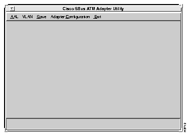
The AAL menu contains the following two options:
The following sections explain the use of these options.
To choose from the available test options, select the Diagnostics/Data Activity option from the AAL menu. The Diagnostics/Data Activity menu displays several options for the available diagnostic tests as follows:
All tests require the same parameters to be specified. Upon selection of any of the options available from the Diagnostics/Data Activity menu, the Test Setup window appears. Figure 6-2 shows an example of a Test Setup window for running all tests.
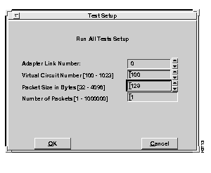
Refer to the following information when setting up any of the tests on the Diagnostics menu:
Select the Run All Tests option to initiate all tests displayed on the Diagnostics/Data Activity menu. The Test Setup window appears, as shown in Figure 6-2. Set up the test parameters, using the information provided in the "Test Setup Window" section. To run all tests, you must first confirm that a loopback cable has been connected and later check that another system is transmitting information over the same virtual circuit at the appropriate time. Refer to Figure 6-5 and Figure 6-8 for examples of the confirmation windows that appear.
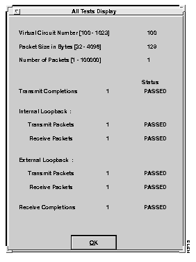
After the parameters have been set and the test has been run, the results appear in the All Tests Display window, as shown in Figure 6-3. The All Tests Display window shows the specified test parameters and the test status. If an error occurs or packets are not received, a message box is displayed.
The receive test requires that another node be transmitting packets on the same VC. If another system is not sending data to the system, the test times out in 20 seconds and a message box is displayed.
While a test is being performed, RUNNING is displayed in the Status column of the Display window. If a test is completed successfully, "PASSED" is displayed in the Status column of the Display window.
If an error occurs during the chosen test, FAILED is displayed in the Status column of the Display window. When you cancel a test from the Run All Tests Setup window, ABORTED appears in the Status column of the Results window. A message box may also be displayed, identifying the nature of the error. If this happens, either modify the parameters in the Test Setup Window or refer to the "Installing the Cisco ATM SBus Adapter Software" chapter to ensure that all steps have been properly performed. If an inexplicable problem persists, refer to Appendix D, "Troubleshooting."
To view cumulative statistical test information, refer to the "Driver Statistics" section later in this chapter.
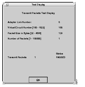
The Transmit Packet test transmits ATM packets from the local system. No network connection is required. Select the Transmit Packet Test option to initiate the Transmit Packet test. The Transmit Packets Test Setup window is displayed, similar to the one shown in Figure 6-2. Set up the test parameters, using the information provided in the "Test Setup Window" section.
After the parameters have been set and the test has been run, the results appear in the Transmit Packet Test display, as shown in Figure 6-4.
The Receive Packet test receives ATM packets from an external VC. An active network connection is required. The receive test requires that another node transmit packets over the same virtual circuit. If another system is not sending data to the system, the test times out in 20 seconds.
Select the Receive Packet Test option to initiate the Receive Packet test. The Receive Packets Test Setup window is displayed, similar to the window shown in Figure 6-2. Set up the test parameters, using the information provided in the "Test Setup Window" section earlier in this chapter.
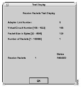
A confirmation window appears, as shown in Figure 6-5. Verify that another system is transmitting data and select OK. After the parameters have been set and the test has been run, the results appear in the Receive Packet Test display, as shown in Figure 6-6.

The Internal Loopback test transmits ATM packets between the local system and the Cisco ATM SBus adapter. No loopback cable is required.
Select the Internal Loopback Test option to initiate the Internal Loopback test. The Internal Loopback Test Setup window is displayed, similar to the screen shown in Figure 6-2. Set up the test parameters, using the information provided in the "Test Setup Window" section.
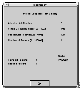
After the parameters have been set and the test has been run, the results appear in the Internal Loopback Test display, as shown in Figure 6-7.
The External Loopback test transmits and receives ATM packets through the local ATM interface connector. A loopback cable is required. If an error occurs during a test or a timeout occurs, a message box indicates the problem.
Select the External Loopback Test option to initiate the External Loopback test. The External Loopback Test Setup window is displayed, similar to the one shown in Figure 6-2. Set up the test parameters, using the information provided in the "Test Setup Window" section.
After the parameters have been set, the Test Confirmation window shown in Figure 6-8 appears. Verify that a loopback cable is connected and select OK.
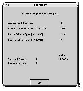
After the test runs, results appear in the External Loopback Test display, as shown in Figure 6-9.

The Driver Statistics menu provides options for displaying statistical information for the adapter. Select the Driver Statistics option from the AAL menu.
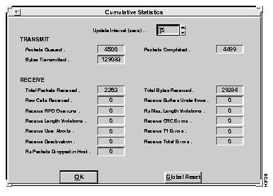
The Display Global Statistics option displays the results of all attributes for the adapter. Cumulative session statistics from all previous transmit and receive tests since the last reset are listed in the display. Any errors that have occurred as a result of testing will also be displayed on this screen. Test results are periodically updated to reflect previous test activity.
To display global statistics, select the Display Global Statistics option from the Driver Statistics submenu. The Cumulative Statistics window appears, as shown in Figure 6-10.
Select the Global Reset option to reset all cumulative session statistics to 0.
The Display Individual VC Statistics option displays the results of all attributes of individual VC statistics. Cumulative VC statistics are listed in the display.
To display these statistics, select the Display Individual VC Statistics option from the Driver Statistics submenu. Enter the update interval to identify how often the test results should update to show previous test results. After the specified number of seconds, the test results are updated to reflect the previous seconds of test activity.
The Individual VC Statistics window appears, as shown in Figure 6-11.
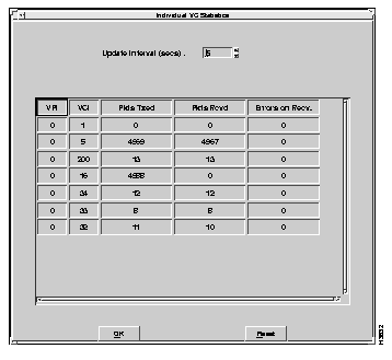
Select the Reset option to reset all cumulative individual VC statistics to 0. The Reset Individual VC Statistics window appears, as shown in Figure 6-12.
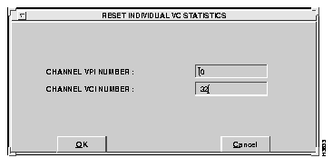
Descriptions of the fields follow:
Enter the appropriate values and select the OK option to reset statistics for an individual virtual circuit.
Virtual LANs (VLANs) and VLAN tables can be configured using the Virtual LAN menu option in the Cisco ATM SBus Adapter utility. These parameters can also be configured by manually modifying the catmlancfg.db file using a text editor, for example vi. For information about manually editing the catmlancfg.db file, refer to the "VLAN Configuration File" appendix.
For information about VLAN parameters that must be considered when setting up VLANs, refer to the "VLAN Considerations" appendix.
Use the options in Cisco ATM SBus Adapter utility to configure the host for ATM communication as follows:
Step 1 Plan the network. Determine the number of VLANs, their associated VLAN numbers, the IP address assignments, and the location of one ATM ARP server for each VLAN.
Step 2 Initialize each VLAN that terminates on the host. Refer to the "Adding a VLAN" section for details.
Step 3 Configure the default VLAN parameters other than ARP table entries or PVC connections. Refer to the "Configuration" section (describes the Virtual LAN configuration window) later in this chapter.
Step 4 Create the appropriate VLAN tables. If the host has an active ATM ARP server table, make any required entries to the ATM ARP server table. Refer to the "VLAN Tables" section later in this chapter for details.
Step 5 Set up any PVC connections. Refer to the "PVC Entries" section later in this chapter for details.
Step 6 Save the configuration of all hosts. Refer to the "Save All Configuration Settings" section later in this chapter for details.
Step 7 Repeat Step 2 through Step 6 for each host with a Cisco ATM SBus adapter.
To display the Virtual LAN Options window, select the VLAN option from the main menu.
The Virtual LAN Options window appears, as shown in Figure 6-13. This window provides access to the configuration and management facilities for virtual LANs. Choose a virtual LAN number.
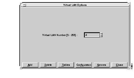
After entering the VLAN number, select the Add option to set up a virtual LAN. The Initialize VLAN window appears, as shown in Figure 6-14. You choose a physical interface number and an associated VLAN type.
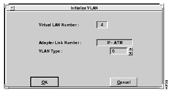
Descriptions of the fields follow:
To initialize a VLAN, select the OK option from the Initialize VLAN window. If the Cisco ATM SBus adapter identifies a problem with the initialization, an error message will appear (for example, "Error in Initializing VLAN"). If an error message appears, check to see if you have already added the VLAN (for example, by selecting the Configuration option from the Virtual LAN Options window).
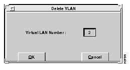
To delete an existing VLAN, select the Delete option from the Virtual LAN Options window. A Delete VLAN confirmation window appears, as shown in Figure 6-15. You must confirm removal of the specified VLAN number from the virtual LAN table before the VLAN is deleted.
Enter the number of the VLAN that you want to delete in the Virtual LAN Number field. Then select the OK option.
To access the various tables needed for VLAN configuration, select the Tables option from the Virtual LAN Options window. The VLAN Table Menu window appears, as shown in Figure 6-16.
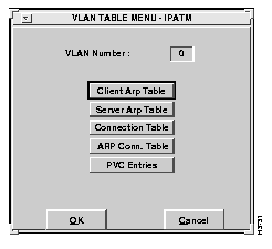
In general, you would set up the VLAN tables as follows:
Choose the appropriate table to edit. Consult the "VLAN Considerations" appendix for additional information on what tables are necessary for your particular network configuration.
A client ARP table is located on each ATM client. After a virtual LAN is initialized, ARP table entries may be added or removed. There are two possible configurations:
This section describes the use of the client ARP table when a server ARP table has been configured and SVC connections are being applied.
The client ARP table contains ATM addresses associated with IP addresses. Data contained in the client ARP table is built both dynamically and statically.
An entry is entered dynamically each time a request for an ATM address is returned from the server ARP table. After the connection between the client and the remote host is established, and information is transferred, the entry remains in the client ARP table. If the connection has not been used for a period of time, the entry is automatically removed from the client ARP table. To keep the client ARP table from getting too large, inactive entries are removed after 20 minutes.
Entries can also be manually added to the client ARP table. These entries are permanently listed in the client ARP table.
This section describes the use of the client ARP table for configurations that do not utilize an ARP server.
Before an application sends a query, you must manually add entries to the client ARP table. In this way, the application may query the client ARP table and find the ATM address of ATM clients. Manual entries in the client ARP table are not deleted, but are kept as permanent entries so they will not be lost.
To review the entries in the client ARP table, select Client ARP table from the VLAN Table menu. The Client ARP table for the specified VLAN appears, as shown in Figure 6-17.
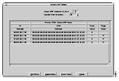
A description of each of the fields follows:
You can add entries to and delete entries from the Client ARP table using the Add Entry and Delete Entry options. You can also delete all entries from the ARP table at one time uisng the Flush Table option. These options are explained in the following sections.
To add an entry to the client ARP table, select the Add Entry option. The Add Client ARP Table Entry window appears, as shown in Figure 6-18.
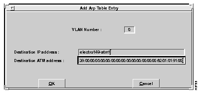
This screen allows entry of the following parameters:
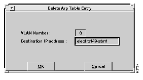
To delete an entry from the client ARP table, select the Delete Entry option from the Client ARP Table window. The Delete ARP Table Entry window appears, as shown in Figure 6-19. Enter the IP address of the entry you want to delete and select OK. The specified IP entry is removed from the client ARP table for the specified VLAN number.
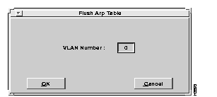
To delete all entries in the client ARP table, select the Flush Table option from the Client ARP Table window. The Flush Arp Table window appears, as shown in Figure 6-20. Enter the number of the VLAN from which you want all client ARP table entries removed, and select the OK option. All entries are removed from the client ARP table for the specified VLAN number.
 | Caution Once all entries in the client ARP table have been deleted, all manual entries will need to be reentered. |
The server ARP table is located on the ARP server (an ATM endstation with the server ARP table designated as "Local"). Refer to the Servers option to designate the location of the server ARP table.
When a client workstation session is started (for example, on boot-up of the system), it automatically contacts the ARP server and adds the IP address and the ATM address of its host adapter to the server ARP table.
When connection to an ATM client is desired, the driver software running on the host workstation first queries the client ARP table (located on the host workstation) to identify the target's ATM address. If the target IP address is not found in the client ARP table, the driver software queries the ARP server.
If an entry in the server ARP table matches the requested IP address, the following occurs:
Upon each successful query of the server ARP table, an entry is added to the client ARP table. After the connection is established and information is transferred, the entry remains in the client ARP table to minimize redundant queries of the ARP server.
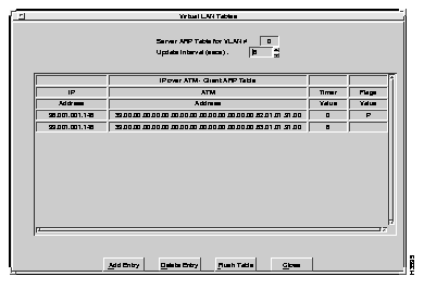
Entries in the server ARP table can only be viewed from the host running the ARP server. To review the entries in the server ARP table, select Server ARP Table from the VLAN Table menu. The server ARP table for the specified VLAN appears, as shown in Figure 6-21.
Descriptions of the fields follow:
You can add entries to and delete entries from the Server ARP table using the Add Entry and Delete Entry options. You can also delete all entries from the Server ARP table at one time uisng the Flush Table option. These options are explained in the following sections.
To manually add an entry to the server ARP table, select the Add Entry option. The Add ARP Table Entry window appears, as shown in Figure 6-22.

Enter the appropriate values in the fields. Descriptions of the fields follow:
To delete an entry from the server ARP table, select the Delete Entry option. The Delete ARP Table Entry window appears, as shown in Figure 6-23.

Enter the appropriate values in the fields. Descriptions of the fields follow:
The currently selected entry is removed from the server ARP table for the specified VLAN number.
To delete all entries in the server ARP table, select the Flush Table option from the Server ARP Table window. The Flush Arp Table window appears, as shown in Figure 6-24. Enter the number of the VLAN from which you want all server ARP table entries removed, and select the OK option. All entries are removed from the server ARP table for the specified VLAN number.

 | Caution Once all entries in the client ARP table have been deleted, all manual entries will need to be reentered. |
The connection table contains all information related to connections for this host over a particular VLAN. This table is used for monitoring connection status and for accumulating statistics. Both PVC and SVC entries are displayed in the table.
Each time an application program sets up a connection between ATM end points on a particular VLAN, an entry is added to the connection table.
To review the entries in the table, select Connection Table from the VLAN Table menu. The Connection Table window displays all connections for the specified VLAN number, as shown in Figure 6-25 and Figure 6-26.
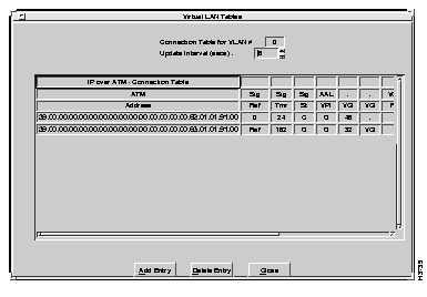
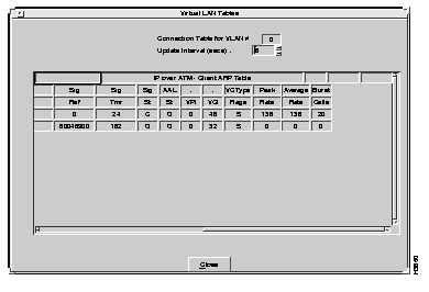
Descriptions of the fields follows:
You can add entries to and delete entries from the Connection table using the Add Entry and Delete Entry options. You can also delete all entries from the Connection table at one time uisng the Flush Table option. These options are explained in the following sections.
To set up a PVC entry or SVC connection and add an SVC entry to the connection table, select the Add Entry option from the Connection Table window. The Add Connection Table Entry window appears, as shown in Figure 6-27.
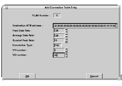
Set the appropriate parameters. The Connection Table window reflects the addition of the entry.
Descriptions of the fields follow:
To delete an entry from the connection table, select Delete Entry from the Connection Table window. The Delete Connection Table Entry window appears, as shown in Figure 6-28.
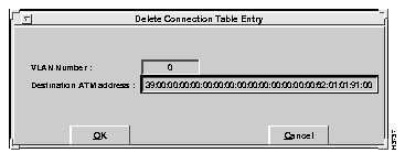
Enter the destination ATM address and select the OK option. The Connection Table window reflects that the entry has been removed.
Selecting the ARP Conn. Table option from the VLAN Configuration menu presents the ARP Connection table. This table is not displayed on one screen. You must use the scroll bar at the bottom of the screen to view the right half of the table. Figure 6-29 shows the left half of the screen, and Figure 6-30 shows the right half of the screen.
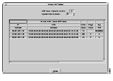
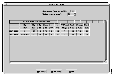
Descriptions of the fields follow:
Selecting PVC Entry from the VLAN Configuration Menu presents the Configure PVC window, as shown in Figure 6-31.
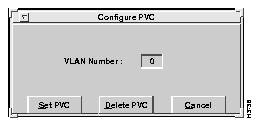
You can add and delete PVC connections using the Set PVC and Delete PVC options, respectively. These options are explained in the following sections.
To add a new PVC connection, select the Set PVC option. The Add PVC Entry window appears, as shown in Figure 6-32.
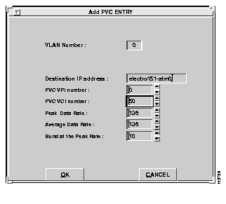
A description of the fields follows:
VLAN Number--The number of the VLAN.
Select the OK option to add the specified PVC entry to the table.
To delete a PVC connection, select the Delete PVC option from the Configure PVC window. The Delete PVC Table Entry window appears, as shown in Figure 6-33.
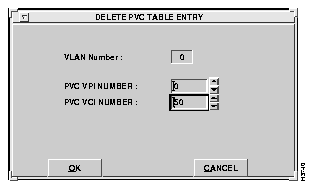
Enter the appropriate parameters. A description of the fields follows:
Select the OK option to remove the specified PVC entry from the table.
Configuration parameters for VLANs, such as information related to the external server services for IP over ATM protocol, can be set and modified using the Configure option.
To configure a virtual LAN, after it has been initialized, select the Configure option from the Virtual LAN Options window. The Virtual LAN Configuration window appears, as shown in Figure 6-34.
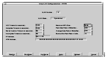
To set configuration parameters for a VLAN, enter the appropriate values in the desired fields.
A description of the fields follows:
To start up the specified VLAN, select the Startup option. The specified VLAN is launched. If an error occurs, review the values and select Startup again.
To shut down the specified VLAN, select the Shutdown option. Operation is terminated for the specified VLAN. An error may occur if the specified VLAN is not currently running.
To get quick access to ARP server information, select the ARP server option. Refer to the "ARP Server" section later in this chapter for information.
To confirm your entry of VLAN configuration parameters, select the Apply option. The VLAN configuration information is stored. The VLAN is not launched unless the Startup option is chosen.
 | Caution If you want to save your configuration values, be sure to select Save from the main menu before exiting the Cisco ATM SBus Adapter utility. |
To refresh the selected VLAN, select the Refresh option.
An ATM ARP server table must be defined to collect and maintain information required for virtual LAN operation. This window controls how the connection to the ARP server is set up.
For systems not using a Cisco 7000 series router as an AIP-based server, at least one host must identify the location of the ARP server as local. All other hosts may then connect to the ARP server to identify the ATM address for other nodes on the same VLAN.
To identify the location of the server ARP table, select the Server option from the Virtual LAN Options window (or from the Virtual LAN Configuration window). The ARP Server Information window appears, as shown in Figure 6-35.
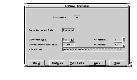
A description of the fields follows:
To start a VLAN, select the Startup option from the ARP Server Information Window, shown in Figure 6-33. The VLAN is initialized for operation.
To shut down a VLAN, select the Shutdown option from the ARP Server Information Window, shown in Figure 6-33. The VLAN is brought out of service.
To get quick access to the VLAN Configuration window, select the VLAN Config option. Refer to the "Configuration" section earlier in this chapter for information.
To confirm your ARP server location entries, select the Apply option. The ARP server values are stored.
 | Caution If you want to save your configuration values, be sure to select Save from the main menu before exiting the Cisco ATM SBus Adapter utility. |
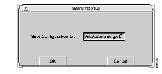
The Save option allows all configuration settings to be saved to disk. Upon selection of the Complete Configuration from the Save submenu, the Save To File window appears, as shown in Figure 6-36.
When you save an existing file, a confirmation window appears, similar to the one shown in Figure 6-36. Select the OK option to proceed with saving the configuration to a file.
Configuration changes made using the Cisco ATM SBus Adapter utility should be saved periodically. If you are confident that the changes are correct, you can save them directly to the catmlancfg.db file, which will be used to configure the VLANs when the system is rebooted. If this is an experimental configuration, it is better to save it to a different file name. It is also a good practice to keep a backup of various versions of the configuration file, catmlancfg.db, to allow you to easily remove the most recent changes. When started, the Cisco ATM SBus Adapter utility retrieves values from the active driver.
To display basic configuration information about the adapter or to set the transmission mode, select the Adapter Configuration option from the Cisco ATM SBus Adapter utility main menu.
The Configure option contains the following two suboptions:
The following sections explain the use of these options.
Select the Display command from the Adapter Configuration menu. The Adapter Configuration Information screen appears, as shown in Figure 6-37.
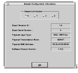
After selecting the desired link from the Adapter Link Number window, the configuration information is displayed in the fields. The fields are defined as follows:
The physical transmission mode can only be set using this utility. It cannot be set using catmlancfg. To set the physical transmission mode, select the Set Transmission Mode option from the Configuration menu.
The Set Transmission Mode option contains the following two suboptions:
The following sections explain the use of these options.
By default, the adapter is set to the U.S. standard SONET mode. To set the adapter to European standard SDH transmission mode, select the SDH option from the Set Transmission Mode menu. The physical transmission mode for the adapter is configured for SDH transmission.
By default, the adapter is set to the U.S. standard SONET mode. However, if the adapter has been changed to SDH mode and you want to change it to SONET transmission mode, select the SONET option from the Set Transmission Mode menu. The physical transmission mode for the adapter is configured for SONET transmission.
|
|