|
|

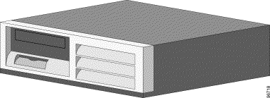
This document provides information for assembling and connecting your Cisco Building Broadband Service Manager (BBSM) Hotspot appliance. (See Figure 1.) If you experience any problems, contact the Cisco Technical Assistance Center, 24 hours a day, 7 days a week, at (800) 553-2447, or send an e-mail to tac@cisco.com. Useful information can also be found at http://www.cisco.com .
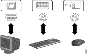
After you open the box containing your BBSM Hotspot appliance, verify that you have an AC power cord, emergency CDs, and additional documentation pertaining to the warranty, operating system, networking adapters, and restore solution. Note that a monitor, keyboard, and mouse are not included.
In addition to the BBSM Hotspot appliance and components, you will need these devices:
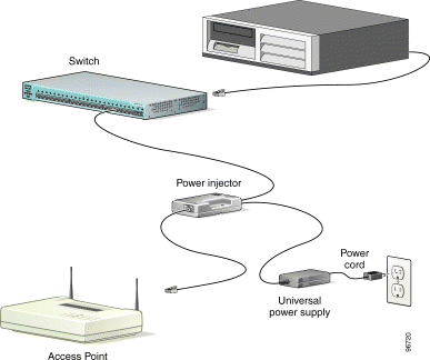
For an example of a Cisco BBSM Hotspot hardware configuration, see Figure 2.
Follow these steps to assemble and connect your Cisco BBSM Hotspot appliance:
Step 2 Plug an AC power cord into the back of the monitor and into the wall jack. (See Figure 4.)
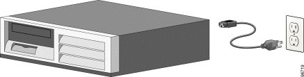
Step 3 Plug an AC power cord into the back of the BBSM Hotspot appliance and into the wall jack. (See Figure 5.)
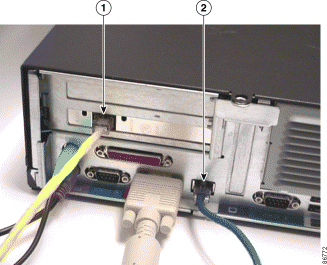
Step 4 Connect an Ethernet cable to the internal NIC port (1) on the back of the BBSM Hotspot appliance (Figure 6), and connect the other end of the cable to the switch, power injector, or wireless access point.
 |
Note If you are using only one access point, you can bypass the switch by connecting an Ethernet crossover cable from the internal NIC port (1) on the back of the BBSM Hotspot appliance directly to the (To Network) end of the power injector, or to the access point, as appropriate. |
Step 5 Connect an Ethernet cable to the external NIC port (2) on the back of the BBSM Hotspot appliance (Figure 6), and connect the other end of the cable to your router, which you use to connect to the Internet.
The Cisco BBSM Hotspot hardware assembly is complete. For network device configuration information, refer to the documentation that came with your Cisco access point, router, or switch.
The following documents provide information about the BBSM Hotspot:
|
Note The most current Cisco documentation for released products is available on Cisco Connection Online (CCO) at http://www.cisco.com . The online documents may contain updates and modifications made after the hardcopy documents were printed. |
This document is to be used in conjunction with the documents listed in the Related Documentation section.
Copyright © 2003, Cisco Systems, Inc.
All rights reserved.
![]()
![]()
![]()
![]()
![]()
![]()
![]()
![]()
Posted: Tue Dec 2 14:09:30 PST 2003
All contents are Copyright © 1992--2003 Cisco Systems, Inc. All rights reserved.
Important Notices and Privacy Statement.