cc/td/doc/product/aggr/10000
hometocprevnextglossaryfeedbacksearchhelp
PDF

Table Of Contents

Cisco Performance Routing Engine 3 Upgrade Installation Guide

Upgrading to a PRE3

Considerations Before Upgrading

Saving the Startup and Running Configuration Information

Tools

Removing the PRE Module

Installing the PRE3 Module

Installing a Redundant PRE3

Troubleshooting

Technical Specifications

Related Documentation


Quick Start Guide

Cisco Performance Routing Engine 3 Upgrade Installation Guide


The Cisco Performance Routing Engine (ESR-PRE3) is a 1-slot module that performs Layer 2 and Layer 3 packet routing and forwarding using Parallel eXpress Forwarding (PXF).

1 Upgrading to a PRE3

This upgrade should be performed by a qualified engineer who is familiar with the Cisco router console interface.


Warning Only trained and qualified personnel are allowed to install, replace, or service this equipment.


Considerations Before Upgrading

This hardware upgrade has an impact on user traffic. The router is not available for user traffic during the upgrade, and traffic cannot resume until the upgrade is complete.


Caution PRE1s and PRE3s cannot operate in the same chassis.

All new PRE3s are shipped with a helper image stored in boot flash memory, and without any configuration.

Make sure you save your configuration information to a TFTP server before removing the old PRE from the chassis.


Caution You cannot save the configuration information to a PRE2 media card to use in a PRE3. When you remove the former PRE from the chassis local configuration information is lost.

Saving the Startup and Running Configuration Information

Use the following procedure to save the configuration information to a TFTP server.


Step 1 Connect the console to the primary PRE.

Step 2 Save the startup configuration and running configuration to the TFTP server.


Tools

Use the following tools to perform the upgrade:

Phillips-head screwdriver

ESD grounding wrist strap


Caution Always wear a grounding wrist strap to prevent ESD damage to the module.

Removing the PRE Module

Use the following procedure to remove the existing PRE module from the chassis.


Step 1 Attach the ESD wrist strap to the chassis to ensure you are properly grounded.

Step 2 Power off the router.


Caution Although PRE modules can be hot-swapped, removing a module terminates all traffic. We recommend that you power off the router to ensure a successful installation.

Step 3 Disconnect all cables from the PRE.

Step 4 Loosen the top and bottom captive screws.

Step 5 Pivot both ejector levers simultaneously to disengage the module from the backplane.

Step 6 Remove the PRE from the chassis and place it on an antistatic surface or in an antistatic bag.

Step 7 If you are replacing a redundant PRE, repeat steps 3 though 6.


Installing the PRE3 Module

Use the following procedure to install the PRE3 module.


Caution To ensure proper operation, always install the primary PRE3 in slot A. If you install a redundant PRE3 in slot B, wait until you have installed and configured the primary PRE3 in slot A before installing the secondary PRE3 in slot B.


Step 1 Attach the ESD wrist strap to the chassis to ensure you are properly grounded.

Step 2 Inspect the backplane connectors on the chassis to make sure there are no bent pins.

Step 3 Slide the module into slot A until you can feel it seat into the backplane (see Figure 1 and Figure 2).

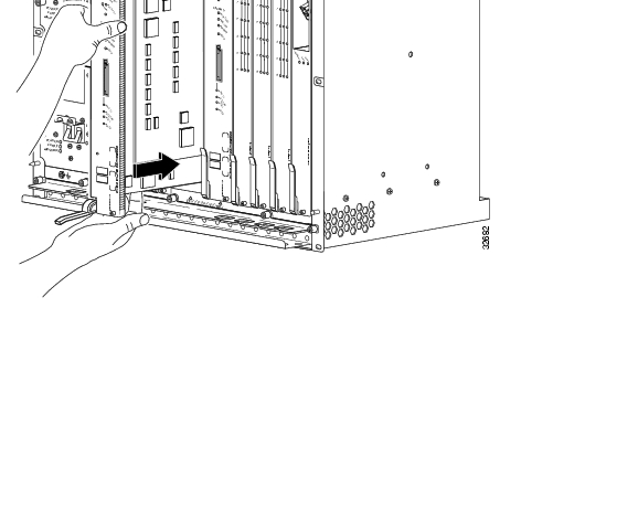
Figure 1 Cisco 10000 Series Router

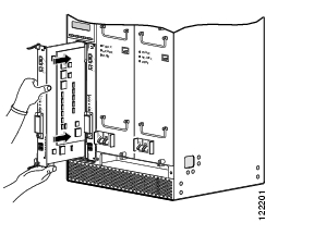
Figure 2 Cisco uBR10012 Router

Step 4 Close the top and bottom ejector levers simultaneously to firmly seat the module to the backplane.

Step 5 Tighten the top and bottom captive screws.

Step 6 Connect all cables to the PRE3 and connect the PRE3 to the console.

Step 7 Power on the router.

Step 8 Boot the full image from the TFTP server.

If you need to access the TFTP server to obtain the full image or the saved configuration files, enter the configuration dialog and enter the information to access the TFTP server.

If you booted the full image, restore the startup and running configuration information, and set the variable for the new image. The upgrade is now complete.

If you booted from the helper image:

Download the full image.

Restore the startup and running configuration information.

Set the boot variable to the new image.

Reload the router.

The upgrade is now complete.


Installing a Redundant PRE3

Use the following procedure to install a redundant PRE3.


Step 1 Repeat Step 1 through Step 8 for slot B (see Installing the PRE3 Module).

Step 2 Set the configuration to boot the full image and reload from the console ROMMON prompt.


2 Troubleshooting

The PRE3 displays the following sequence of events when booted:

The FAIL LED lights briefly, followed by a flashing STATUS LED, and progress messages appear on the PRE3 display.

IOS RUN appears after a successful boot.

The STATUS LED remains on (green).

If this sequence does not occur, check the following:

Check to see if the LEDs on the other modules are operating. If not, check for a problem in the power subsystem.

Remove the PRE3 and check for bent or broken pins on the backplane connectors.

Verify the status of the PRE3s internal Ethernet interface (ethernet 0/0/0). If this interface is down it could indicate that the PRE3 is not fully seated in the slot, or that a hardware failure occurred.


Note Do not confuse the PRE3 internal Ethernet interface (ethernet 0/0/0) with the module's external Fast Ethernet interface (fastethernet 0/0/0) which is used for network management or remote access.


Refer to Table 1 for LED and switch descriptions.

Table 1 LED and Switch Descriptions

LED/Switch
Description

ACTIVITY

On (green)

Off

Packets are being transmitted and received.

No packet activity.

LINK

On (green)

Off

Carrier detected and passing traffic.

No carrier detected and not passing traffic.

CRITICAL

MAJOR

MINOR

Off

On (yellow)

No alarm.

Alarm condition is present.

STATUS

On (green)

Off

PRE3 is ready.

No power to PRE3, or it is acting as the redundant PRE3.

FAIL

Off

On (yellow)

PRE3 is operating properly.

PRE3 is disabled caused by a major failure.

ACO1 switch

Disables the audible alarm.

1 Alarm cutoff


3 Technical Specifications

The following table provides the PRE3 specifications.

Description
Part Number/ Specification

PRE3

PRE3 spare

ESR-PRE3

ESR-PRE3=

Weight

9 lbs.

Power consumption per PRE3 module

145W (495 BTU/hour) nominal

200W (683 BTU/hour) maximum


4 Related Documentation

The release notes, regulatory compliance and safety information, and user guides for Cisco products are available online at www.cisco.com.


hometocprevnextglossaryfeedbacksearchhelp

Posted: Tue Dec 5 12:37:11 PST 2006
All contents are Copyright © 1992--2006 Cisco Systems, Inc. All rights reserved.
Important Notices and Privacy Statement.