|
|

Table Of Contents
Cisco 10000 Series Router Performance Routing Engine Installation
Performance Routing Engine Connectors
Replacement Installation Guidelines
Removing the Cisco 10008 Front Cover
Installing or Replacing the PRE
Synchronizing PRE Configurations
Forcing Failover in a Redundant Pair
Upgrading Software on a Single PRE
Upgrading Software on Redundant PREs
Managing System Boot Parameters
Changing the Software Configuration Register Settings
Configuration Register Settings
Upgrading from an ESR-PRE or ESR-PRE1
to an ESR-PRE2Troubleshooting the Installation
Managing the Router Using the Network Management Ethernet Port
Configuring the NME Port—ESR-PRE and ESR-PRE1
Configuring the NME Port—ESR-PRE2
Analyzing and Troubleshooting Packets
Packet Statistics and PXF Counters
Cisco Product Security Overview
Reporting Security Problems in Cisco Products
Obtaining Technical Assistance
Cisco Technical Support & Documentation Website
Definitions of Service Request Severity
Obtaining Additional Publications and Information
Cisco 10000 Series Router Performance Routing Engine Installation
Product Numbers: ESR-PRE, ESR-PRE1, and ESR-PRE2
Document Version History
This is the third version of this document. The document version history beginning with this online part number is in Table 1.
This publication contains instructions for installing and upgrading the Performance Routing Engine (PRE) in a Cisco 10000 series router. Contents
The following sections are included in this configuration guide:
•
Prerequisites and Preparation
•
•
•
•
•
•
•
•
Related Documentation
For more information about the Cisco 10000 series router, see the following documents:
•
•
•
•
Product Overview
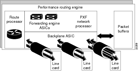
The PRE performs all Layer 2 and Layer 3 packet manipulation related to routing and forwarding through the Cisco 10000 series ESR. Its advanced application-specific integrated circuit (ASIC) technology supports very high performance throughput with IP services enabled on each port.
The PRE runs Cisco IOS Release 12.0(S). It contains two PCM/CIA slots, 32 MB of Flash memory, and a packet buffer of up to 256 MB. It supports up to 512 MB of SDRAM. Two PREs can be configured in a single chassis for redundancy.
The PRE is implemented on two printed circuit board assemblies:
•
•
Figure 1 Distributed Processing Architecture in the PRE
Redundant PREs
You can configure two PREs in a single chassis for redundancy. If the primary PRE fails, the secondary PRE automatically takes over operation of the router. Because all the line cards are physically connected to both the primary and secondary PREs, the failure of a single PRE does not require user intervention. If a failure occurs, all line cards automatically reset to the redundant PRE.
With redundant PREs, the Cisco 10000 series ESR can survive even a catastrophic processor failure and still maintain the highest levels of uptime and availability. Startup and running configurations of the secondary PRE are synchronized with the primary PRE, ensuring the fastest possible cut-over time if the primary PRE fails.
Forwarding Path
The Cisco 10000 series ESR forwarding path comprises a unique blend of hardware and microcoded processors that yields high forwarding rates with considerable flexibility for future growth in packet processing features.
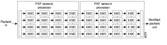
The forwarding path is centered around a pair of Cisco-designed multiprocessor ASICs called parallel express forwarding (PXF) network processors. Each PXF network processor provides a packet processing pipeline consisting of 16 microcoded processors, arranged as multiple pipelines.
Each of the 16 processors in a PXF network processor is an independent, high-performance processor, customized for packet processing. Each processor, called an eXpress microcontroller (XMC), provides a sophisticated dual-instruction-issue execution unit, with a variety of special instructions designed to execute packet processing tasks efficiently.
In addition to processing packets, XMCs have access to on-chip resources such as register files and timers. They also have shared access to very large off-chip memories for storing state information, such as routing tables and packet queues.
Within a single PXF network processor, the 16 XMCs are linked together in four parallel pipelines. Each pipeline comprises four XMCs arranged as a systolic array, where each processor can efficiently pass its results to its neighboring downstream processor. Four parallel pipelines are used, to increase throughput.
Within the Cisco 10000 series ESR, two PXF network processor ASICs are used, yielding four parallel processing pipelines, each containing eight processors in a row.
Figure 2 Cisco 10000 Series ESR Forwarding Path Processor Array
In the array of processors in , hardware, microcode, and Cisco IOS software resources provide advanced, high-touch feature processing on the Cisco 10000 series ESR. The allocation of features to XMCs in the processor pipeline is flexible and continues to change as new features are added.
The PXF network processor architecture allows all 32 independent processors to work efficiently on per-packet feature processing, yielding high throughput while still allowing substantial feature processing.
By centralizing packet processing in the PRE, the Cisco 10000 series ESR architecture frees up space on line cards, enabling high interface density, yet retaining the compact NEBS transmission equipment form factor.
Route Processor
The second component of the PRE is the route processor (RP), a high-speed, conventional microprocessor that has special interfaces to the forwarding path:
•
•
The RP also includes such standard Cisco IOS facilities as Flash memory, NVRAM for storing configuration files, and Ethernet connections for network management. This familiar environment makes possible a simple transition from existing Cisco IOS-based routers to the Cisco 10000 series ESR platform.
PRE Faceplates
The faceplates of the PRE, PRE-1, and PRE-2 are shown in this section.
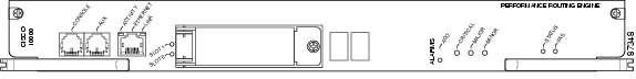
Figure 3 Performance Routing Engine, Product Number ESR-PRE, Front Panel
Figure 3 shows the front panel of the Performance Routing Engine, product number ESR-PRE.
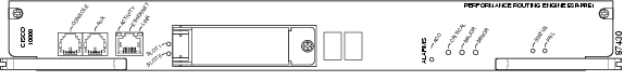
Figure 4 Performance Routing Engine, Product Number ESR-PRE1, Front Panel
Figure 4 shows the front panel of the Performance Routing Engine, product number ESR-PRE1.
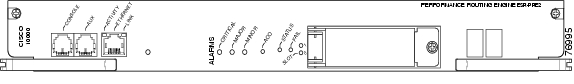
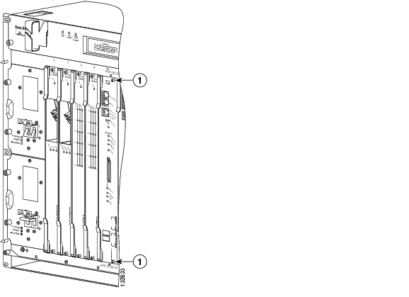
Figure 5 Performance Routing Engine, Product Number ESR-PRE2, Front Panel
Figure 5 shows the front panel of the Performance Routing Engine, product number ESR-PRE2.
Performance Routing Engine Connectors
The front panel on the PRE contains three ports with RJ-45 connectors (see Figure 3, Figure 4, or Figure 5):
•
•
•
PCMCIA Card Slots
Two PCMCIA Type II card slots can store the Cisco IOS software image or a system configuration file on a Flash disk memory card. The system can also boot from the software stored on the Flash disk memory card.
LED Indicators and Switches
LEDs on the front panel of the PRE provide a visual indication showing the status of PRE operation. The LEDs are separated into three categories: alarms, status, and failure.
•
•
•
See Table 4 for a complete description of the PRE LEDs.
Prerequisites and Preparation
Before you perform any of the procedures in this guide, Cisco recommends that you:
•
•
•
•
•
–
–
–
Safety Guidelines
Before you begin the PRE installation procedure, review the safety guidelines in this section to avoid injuring yourself or damaging the equipment. Before you install, configure, or perform maintenance on the router, you should also review the safety warnings listed in the Regulatory Compliance and Safety Information for Cisco 10000 Series Routers document.
Safety Warnings
Safety warnings appear throughout this publication in procedures that, if performed incorrectly, may harm you. A warning symbol precedes each warning statement. The following warning is an example of a safety warning. It identifies the warning symbol and associates it with a bodily injury hazard.
Warning
Note
Software Compatibility
The ESR-PRE, ESR-PRE1, and ESR-PRE2 have specific Cisco IOS software requirements.
Table 2 shows the minimum required Cisco IOS software for each PRE.
Table 2 PRE Software Compatibility
ESR-PRE
12.0SL
Cisco IOS Release 12.0(9)SL1
ESR-PRE1
12.0SL
Cisco IOS Release 12.0(9)SL
12.0ST
Cisco IOS Release 12.0(20)ST
12.0SX
Cisco IOS Release 12.0(21)SX
ESR-PRE2
12.2BX
Cisco IOS Release 12.2(15)BX
1 The last (and latest) Cisco IOS software release to support the ESR-PRE is 12.0(20)ST
Use the show version command to display the system software version that is currently loaded and running.
If the output of the show version command indicates that the Cisco IOS software is a version earlier than the version identified as the minimum Cisco IOS software release in Table 2, check the contents of Flash memory to determine if the required images are available on your system.
The output of the show flash command provides a list of all files stored in Flash memory. If the correct software version is not installed, contact Cisco Customer Service (see the "Obtaining Technical Assistance" section).
Installation Guidelines
This section contains guidelines for the following:
•
•
•
The Cisco 10000 router is hot-swappable which means you can remove and replace a PRE while the system is operating—if you have a secondary (redundant) PRE installed in the chassis. This feature allows you to add, remove, or replace a PRE while the system maintains all routing information and ensures session preservation.
Caution
Caution
New Installation Guidelines
If you are replacing the PRE in a non-redundant system, you must configure the PRE using the configure command. For configuration information, refer to the "Configuring the PRE" section.
Replacement Installation Guidelines
If the PRE is replaced in a redundant system containing two PREs, the secondary (or newly installed) PRE automatically assumes the configuration of the primary PRE; do not configure the new PRE.
Required Tools and Equipment
You need the following tools and equipment to install the PRE:
•
•
•
Removing the Cisco 10008 Front Cover
Use the following procedure to remove the front cover from the Cisco 10008 router.
•
•
•
Figure 6 Inserting a Screwdriver Blade Into a Bezel Latch
Figure 7 Unlocking the Bezel Latch
Step 1
Repeat this procedure for all four bezel latches and then remove the latches.
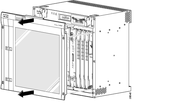
Figure 8 Removing the Front Cover from the Cisco 10008 Router
Step 2
Powering Off the System
If you are installing or replacing a system with a single PRE, you must power down the system.
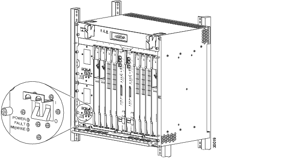
Figure 9 Setting DC Power Switch to the Off Position
Step 1
Step 2
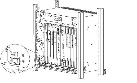
Figure 10 Setting AC Power Switch to the Off Position
Go to "Removing a PRE" section or "Installing a PRE" section.
Installing or Replacing the PRE
This section describes how to install or replace the PRE in the Cisco 10000 chassis. It contains the following procedures:
Also see the "Troubleshooting the Installation" section.
Installing a PRE
Use the following procedure to install the PRE into slot 0A or slot 0B in the Cisco 10000 chassis.
Note
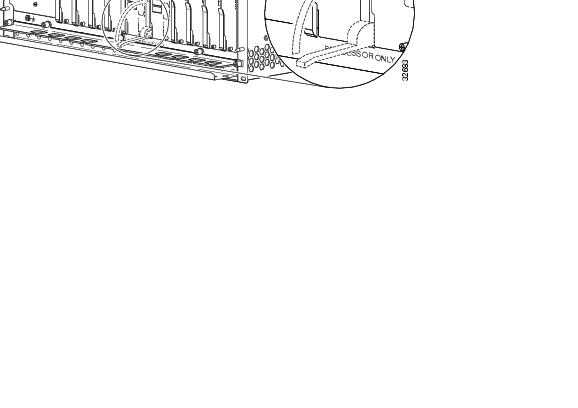
Figure 11 ESD Chassis Connection
Step 1
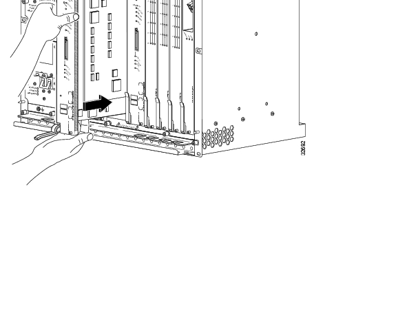
Figure 12 Inserting the PRE
Step 2
Step 3
Figure 13 Closing the Ejector Levers
Step 4
The PRE cycles through its power-on self-test. The Fail LED stays on briefly (10 to 15 seconds) and then shuts off. If the Fail LED remains on, go to the "Troubleshooting the Installation" section
Step 5
Caution
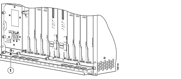
Figure 14 Captive Screw Locations
Step 6
Caution
Step 7
Configuring the PRE
After the PRE is successfully installed, you can configure it for network use. For information about configuring the PRE, see the "Managing the Router Using the Network Management Ethernet Port" section, and other sections in this document.
Note
Removing a PRE
Use the following procedure to remove a PRE from the chassis:
Figure 15 ESD Chassis Connection
Step 1
Figure 16 Captive Screw Locations
Step 2
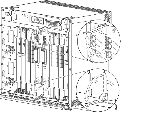
Figure 17 Opening the Ejector Levers
Step 3
Step 4
Step 5
If you are not installing a replacement PRE, install a blank faceplate in the slot.
Warning
Step 6
Step 7
Managing PRE Redundancy
This section explains how to manage redundant PRE failover methods.
Synchronizing PRE Configurations
You do not need to specify redundancy between PREs. If two PREs are installed in the Cisco 10000 series router, they automatically act as a redundant pair.
In the default state, redundant PREs are configured to automatically synchronize all critical files. You can use the auto-sync command to specify which files should be synchronized.
Step 1
Router(config)# redundancyStep 2
Router(config-r)# main-cpuStep 3
Router(config-r-mc)# auto-sync startup-configAny configuration options entered in the main-cpu submode act only on the primary PRE, not on the secondary PRE.
The following lists the options for the auto-sync command:
auto-sync [startup-config | running-config | bootvar | config-register | standard][no] auto-sync [startup-config | running-config | bootvar | config-register | standard]Where:
•
Use the no form of the command to turn off startup configuration synchronization.
•
Use the no form of the command to turn off running-config synchronization.
•
Use the no form of the command to turn off boot variables synchronization.
•
Use the no form of the command to turn off config-register synchronization.
•
Use the no form of the command to turn off all of the above auto-synchronization features.
The default for the auto-sync command is auto-sync standard.
Forcing Failover in a Redundant Pair
To manually force the primary and secondary devices in a redundant pair to failover, use the redundancy force-failover command. Manually force the primary and secondary PREs to reverse roles if you need to replace the primary one. You can then replace the PRE while causing only minimal disruption of traffic.
Router# redundancy force-failover main-cpuThis command does not generate an alarm as a hardware reset does.
The following example shows how to set the secondary PRE to be active:
Router# redundancy force-failover main-cpuUpgrading Software
This section describes methods for upgrading Cisco IOS images on the Cisco 10000 series router.
Upgrading Software on a Single PRE
To upgrade software for a single PRE, follow these steps:
Step 1
Router# copy tftp disk0:Address or name of remote host [172.31.53.64]?Source filename [c10000/c10k-p6-mz]?c10000/c10k-p6-mzAccessingtftp://172.31.53.64/c10000/c10k-p6-mz.Loading c10000/c10k-p6-mz from172.31.53.64 (via FastEthernet0/0/0):!!!!!!!!!!!!!!!!!!!!!!!!!!!!!!!!!!!!!!!!!!!!!!!!!!!!!!!!!!!!!!!!!!!!!!...[OK - 5717476/11433984 bytes]5717476 bytes copied in 250.840 secs (22869 bytes/sec)Router#Step 2
Router(config)# boot system flash disk0:c10k-p6-mzStep 3
Router# copy running-config startup-configStep 4
Router# reloadThe system is now using the new Cisco IOS image.
Upgrading Software on Redundant PREs
This section tells you how to upgrade software on redundant PREs. For the procedure described here to work, PRE redundancy should be configured as auto-sync standard (the default). See the "Synchronizing PRE Configurations" section.
Step 1
Router# copy tftp disk0:Address or name of remote host [172.31.53.64]?Source filename [c10000/c10k-p6-mz]?c10000/c10k-p6-mzAccessingtftp://172.31.53.64/c10000/c10k-p6-mz.Loading c10000/c10k-p6-mz from172.31.53.64 (via FastEthernet0/0/0):!!!!!!!!!!!!!!!!!!!!!!!!!!!!!!!!!!!!!!!!!!!!!!!!!!!!!!!!!!!!!!!!!!!!!!...[OK - 5717476/11433984 bytes]5717476 bytes copied in 250.840 secs (22869 bytes/sec)Router#Step 2
Router# copy tftp sec-disk0:The output is the same as that shown in Step 1.
Step 3
Router(config)# boot system flash disk0:c10k-p6-mzStep 4
Router# copy running-config startup-configStep 5
Router# hw-module sec-cpu resetStep 6
Router# redundancy force-failover main-cpuBoth PREs are now running the new Cisco IOS image.
Managing System Boot Parameters
This section tells you how to use IOS to modify PRE boot parameters.
During the boot process, the system reads a software configuration register that defines certain system parameters. The software configuration register is a 16-bit register in NVRAM used to define such characteristics as:
•
•
•
By modifying the boot parameters, you can customize your Cisco 10000 series router. For example, a common configuration register setting in some lab environments is 0x2100. Using this setting, the system boots to the ROM monitor prompt, where a technician can load a specific image by entering the boot command at the rommon prompt. (For more information, see the Cisco IOS Configuration Fundamentals Configuration Guide.)
Changing the Software Configuration Register Settings
To change the software configuration register settings while you are running system software, perform the following steps:
Step 1
Router(config)#config-register 0x2100Consult the hexadecimal column in Table 3 for the possible settings to enter as the 4-bit value parameter.
Step 2
Router(config)# Ctrl-Z
Router#
The new contents of the software configuration register are saved to NVRAM. These new settings do not take effect until you reload the system or reboot the router.
Step 3
Router#show version ... #Configuration register is 0x141 (will be 0x2100 at next reload)Step 4
Router# copy running-config startup-configStep 5
The software configuration register setting takes affect only after you reload the system. This happens when you issue the reload command from the console or reboot the router.
Configuration Register Settings
Table 3 summarizes the modifications that you can make to the software configuration register. For detailed information, refer to the Cisco IOS Configuration Fundamentals Command Reference.
Note
Upgrading from an ESR-PRE or ESR-PRE1
to an ESR-PRE2This section describes the procedures for upgrading the Performance Routing Engine from an ESR-PRE or ESR-PRE1 to an ESR-PRE2. Procedures for downgrading from an ESR-PRE2 to an ESR-PRE1 or ESR-PRE are also described.
•
Prerequisites
For all of the software features supported by your current ESR-PRE (c10k-p6-mz) or ESR-PRE1 (c10k-p10-mz) image to function correctly, they must be supported by the ESR-PRE2 (c10k2-p11-mz) image. Please check with your Cisco marketing representative to verify the correct upgrade path before initiating the upgrade.
The upgrade should be performed by a qualified engineer. This person must be familiar with the Cisco router console interface and be able to perform basic router operations, such as configuration loading and router reload functions.
Caution
Upgrade Considerations
•
•
•
•
If the media card has enough space, the new ESR-PRE2 image can also be copied there, which will save time later on. If you desire to do this, download the latest ESR-PRE2 (c10k2-p11-mz) image from the TFTP server to the removable media card in disk0/1 or slot0/1.
Note
Upgrade Procedures
This section contains several upgrade procedures:
•
•
•
Upgrading the Primary PRE to an ESR-PRE2
Follow this procedure to upgrade:
•
•
Step 1
Step 2
If you save to a flash-based media card, and you have a redundant pair of ESR-PREs or ESR-PRE1s installed in the chassis, be sure that you save the startup and running configuration to both flash-based media cards on both ESR-PREs or ESR-PRE1s.
Caution
Step 3
Note
Step 4
Step 5
Note
Step 6
Step 7
Note
Step 8
Booting from a TFTP Server
If you saved the ESR-PRE2 image on a TFTP server that is reachable from the router (for example, if the router and server are on the same LAN or there is a default proxy server), boot the router from the TFTP server.
In the following example, the router boots the ESR-PRE2 (c10k2-p11-mz) image from a network server with the IP address 172.16.15.112:
> boot tftp://172.16.15.112/c10k2-p11-mzThe configuration dialog appears.
You can now proceed to step 9.
Booting from a Flash-Based Media Card
If the image was saved to the flash-based media card, boot that image.
The following boot command loads the ESR-PRE2 image from the media card:
> boot system flash disk0:c10k2-p11-mzThe configuration dialog appears.
You can now proceed to step 9.
Booting from the Helper Image
If you did not save the ESR-PRE2 image to either a TFTP server or a flash-based media card, boot the helper (c10k-eboot-mz) image, which is shipped with the ESR-PRE2 boot flash memory.
In the following example, the router boots from the helper image:
> boot c10k-eboot-mzThe configuration dialog appears.
Proceed to the "Did Not Save the Configuration" section.
Step 9
Saved the Configuration on a Flash-Based Media Card
If you booted the c10k2-p11-mz image, and you saved the previous configuration to a flash-based media card:
a.
b.
The router is available for normal operations and the upgrade is complete.
Saved the Configuration on a TFTP Server
If you booted the c10k2-p11-mz image, and you saved the previous configuration to a TFTP server:
a.
b.
c.
d.
The router is available for normal operations and the upgrade is complete.
Did Not Save the Configuration
If you did not save the ESR-PRE2 image to either a TFTP server or a flash-based media card, and you booted the helper (c10k-eboot-mz) image:
a.
b.
c.
d.
Upgrading the Secondary PRE of a Redundant Pair of PREs to an ESR-PRE2
If you have a secondary, redundant ESR-PRE2 to install in the chassis, use the following procedure:
Step 1
Step 2
Step 3
a.
b.
If you do not have any removable media devices, then you upgrade this redundant ESR-PRE2 as if it was a single ESR-PRE2:
a.
b.
Note
The redundant ESR-PRE2 upgrade is now complete, and the router is available to resume normal operations.
Reversing an Upgrade to an ESR-PRE2
Use the following procedure to reinstall an ESR-PRE or ESR-PRE1 (or redundant PREs) after upgrading to an ESR-PRE2.
Step 1
Step 2
Step 3
Step 4
Troubleshooting the Installation
Refer to Table 4 for descriptions of the LEDs on the PRE. Follow the instructions in Table 5 on the next page to troubleshoot the installation.
Figure 18 PRE-1 LEDs
See Figure 3 and Figure 5 for illustrations of the PRE and PRE-2 faceplates.
If these troubleshooting procedures do not correct the problem, refer to the Cisco 10000 Series Router Troubleshooting Guide for additional information.
Managing the Router Using the Network Management Ethernet Port
The network management Ethernet (NME) port on the performance routing engine (PRE) is used to manage the Cisco 10000 router. The duplex mode and speed of the NME port are configurable, depending on the PRE installed in the router's chassis. The Cisco 10000 router supports the following PREs:
•
•
•
The following sections describe how to configure the duplex mode and speed of the NME port for specific PREs.
Configuring the NME Port—ESR-PRE and ESR-PRE1
The NME port for ESR-PRE or ESR-PRE1 supports the following operational modes:
•
•
•
Default configurations do not appear in the router's configuration file.
We recommend that you allow the NME port to autonegotiate the duplex mode. When autonegotiation mode is enabled, the NME port responds only to 802.3x pause frames from another device.
If the negotiation of duplex mode fails and a duplex mode mismatch occurs, manually set the duplex mode for full-duplex or half-duplex operation. Setting duplex mode disables autonegotiation mode. When you manually set duplex mode, the NME port does not support 802.3x flow control.
When you manually configure duplex mode, the NME port can experience problems such as flapping. If this occurs, disable duplex mode by entering the no full-duplex or no half-duplex command. When you enter the no duplex command, the operational mode reverts to autonegotiation mode.
To configure the NME port, perform the following optional configuration tasks:
•
•
Manually Setting the Duplex Mode for the NME Port—ESR-PRE or ESR-PRE1
Note
To manually set the duplex operational mode of the NME port for ESR-PRE or ESR-PRE1, enter either of the following commands in interface configuration mode:
Manually Setting the Speed for the NME Port—ESR-PRE or ESR-PRE1
The Cisco IOS software automatically negotiates the speed of the NME port for ESR-PRE or ESR-PRE1. You cannot manually set the speed of the NME port.
Configuring the NME Port—ESR-PRE2
The NME port for ESR-PRE2 supports the following operational modes:
•
•
•
The NME port defaults to 100 Mbps full-duplex mode. Default configurations do not appear in the configuration file.
To configure the NME port, perform the following optional configuration tasks:
•
•
Manually Setting the Duplex Mode for the NME Port—ESR-PRE2
To manually configure the duplex mode of the NME port for ESR-PRE2, enter the following command in interface configuration mode:
Manually Setting the Speed of the NME Port—ESR-PRE2
To manually set the speed of the NME port for ESR-PRE2, enter the following command in interface configuration mode:
Analyzing and Troubleshooting Packets
The Parallel eXpress Forwarding (PXF) engine of the Performance Routing Engine (PRE) is responsible for processing and forwarding packets. As processing occurs, PXF counters increment to reflect the internal behavior of the PRE. The router collects this statistical information from the counters and appropriately displays it when you enter specific show pxf cpu commands. The output from these commands is useful in analyzing and troubleshooting denied and logged packets.
To correctly interpret packet statistics, it is important that you understand the behavior of the router during packet and access list processing, and the counters that provide the statistical data. This section briefly describes access list processing, some PXF counters and their behavior, and some of the commands you can use to display statistical information. This section is based on ESR-PRE2 with differences noted for ESR-PRE and ESR-PRE1.
Access Control Lists
The Cisco 10000 series router provides traffic filtering capabilities using access control lists (ACLs). Access lists filter network traffic by controlling whether routed packets are forwarded or blocked at the router's interfaces. Using ACLs, you can do such things as restrict the contents of routing updates, provide traffic flow control, and provide security for your network.
The Cisco 10000 series router supports the following ACL types and features:
•
•
•
•
•
•
The access-list command is used to configure an ACL. For example, the following configuration creates ACL 108:
access-list 108 permit udp any host 10.68.1.10 range 0 5000 logaccess-list 108 permit udp host 10.1.1.10 range 0 5000 any logAfter creating an ACL, it is applied to an interface using the ip access-group command. The router executes the ACL from top to bottom, denying or permitting packets as directed by the access-list entries (ACEs). When the log keyword is specified in an ACE, the router sends packet information to the console.
The last line of an ACL is an implicit deny statement that appears to the router as:
deny any anyThis statement causes the router to deny any packets remaining after processing the ACEs of the access list. The implicit deny statement does not include the log keyword; therefore, the router does not send packet information to the console for those packets denied by the implicit deny statement.
For example, the router processes the following ACL from top to bottom as follows:
access-list 108 permit udp any host 10.68.1.10 range 0 5000 logaccess-list 108 permit udp host 10.1.1.10 range 0 5000 any log•
•
•
Packet Statistics and PXF Counters
The Cisco 10000 router Performance Routing Engine (PRE) provides high performance Layer 3 processing using its Parallel eXpress Forwarding (PXF) engine and Route Processor (RP). The PRE installed in the chassis can be a ESR-PRE, ESR-PRE1, or ESR-PRE2.
As the PXF engine processes packets, counters such as the following reflect the internal operation of the PRE:
•
•
•
The statistical information that the PXF counters provide is useful in analyzing and troubleshooting denied and logged packets. Because the internal operation of the ESR-PRE/ESR-PRE1 and ESR-PRE2 differs for ACLs, the PXF counters are inconsistent between the PREs. However, system-wide router behavior is consistent for ESR-PRE1 and ESR-PRE2 despite the differences in counters.
The following sections describe the PXF counters and the way in which they increment.
IP Forwarding Counter
A forwarding information base (FIB) lookup is one of the initial steps in forwarding a packet. When the router forwarding processor needs information to forward a packet, it performs a lookup operation on the FIB table. The IP forwarding counter reflects the state of that lookup operation. It does not reflect whether or not the packet was forwarded. This counter increments each time a FIB lookup successfully occurs.
ICMP Created Counters
Some FIB lookup operations can cause ICMP messages to be generated. For example, if a packet's time-to-live (TTL) expires, an address is unreachable, or an ACL-denied packet is dropped, an ICMP message is generated. The ICMP created counters reflect the number of ICMP packets created. The counters increment each time a FIB lookup results in the generation of an ICMP message.
Feedback Counter
Sometimes the PXF engine cannot complete the processing of a packet before the packet completes a single pass through the PXF; the packet requires additional processing. As a result, the packet is fed back through the PXF and processing continues. This is referred to as a feedback operation.
The following are examples of packets that can cause feedbacks to occur:
•
•
•
The feedback counter reflects the total number of feedbacks through the PXF by all packets. The counter increments one time for each additional pass a packet makes.
When a packet is denied because of an ACL deny statement, the router drops the packet. Dropped packets do not need further processing and, therefore, are not fed back through the PXF. In this case, the feedback counter does not increment.
Displaying Packet Statistics
The Cisco 10000 router supports show pxf cpu commands that allow you to do such things as determine the:
•
•
•
•
•
The show pxf cpu commands used to display packet statistics differ between the ESR-PRE/ESR-PRE1 and the ESR-PRE2. For the ESR-PRE or ESR-PRE1, the commands are show hardware pxf cpu; for the ESR-PRE2, the commands are show pxf cpu.
To display packet statistics for the ESR-PRE2, enter any of the following commands:
Sample Case Study
For the purposes of this case study, assume that the following ACL is configured on the router's outbound serial 1/0/0 interface:
access-list 108 permit udp any host 10.68.1.10 range 0 5000 logaccess-list 108 permit udp host 10.1.1.l0 range 0 5000 any logA traffic simulator is used to send 100 UDP packets to the Cisco 10000 router with the source and destination ports of the packets set to 6000. Packets arrive on the Gigabit Ethernet 2/0/0 interface and are supposed to leave the router through the serial 1/0/0 interface.
After processing the 100 UDP packets, the show pxf cpu commands are entered to display statistical information about the packets.
Hardware and Software Components
Table 6 lists the hardware and software components used in the case study.
Table 6 Hardware and Software Components
Experimental version 12.0
ESR-PRE2
c10k-p8-mz.weekly.03272002
Filtering the Traffic
On the outbound serial 1/0/0 interface, the Cisco 10000 router filters the 100 packets sent by the traffic simulator using the ACL applied to the interface. The router executes the ACL from top to bottom in the following way:
access-list 108 permit udp any host 10.68.1.10 range 0 5000 logaccess-list 108 permit udp host 10.1.1.10 range 0 5000 any log•
•
•
Remember, the 100 UDP packets were sent with a source and destination port of 6000. As the router executes the ACL, none of the 100 packets matches ACL statements 1 and 2 because of the different port numbers. The router then executes the implicit deny statement.
The implicit deny statement terminates any ACL. This statement tells the router to deny all other traffic. Because the 100 packets did not match statements 1 and 2, the router then executes the deny all statement and denies the packets.
Displaying Packet Statistics for ACLs
The show pxf cpu statistics security command provides statistical information about the packets denied, permitted, and logged by ACLs. The router collects statistics for mini-compiled ACLs, but not for turbo-compiled ACLs.
The following example output provides packet information before sending the 100 packets. Notice that the Packets Denied field indicates that no packets have been denied by ACL 108. The Denied and Log field indicates that no denied packets have been logged.
Router# show pxf cpu statistics securityACL Pkts Pkts Denied PermitName Denied Permitted & Log & Log108 0 0 0 0The following example output results after sending the 100 packets. Notice that the Packets Denied field now indicates that 100 packets have been denied. Recall that the router denied the packets because they matched the implicit deny statement. This statement does not include a log keyword, which causes information to be sent to the console. Therefore, no logging occurs. Notice that the Denied and Log field correctly indicates this.
Router# show pxf cpu statistics securityACL Pkts Pkts Denied PermitName Denied Permitted & Log & Log108 100 0 0 0Displaying IP Forwarding Statistics
The show pxf cpu statistics ip command provides statistical information about IP forwarding. The following example output indicates the count of the IP forwarding counter before sending the 100 packets. Notice that the count is 402.
Router# show pxf cpu statistics ipFP ip statisticsdropped 0forwarded 402punted 540input_packets 942icmps_created 0noadjacency 0noroute 0unicast_rpf 0...The following example output results after sending the 100 packets. Notice that the IP forwarding counter is now 502.
Router# show pxf cpu statistics ipFP ip statisticsdropped 0forwarded 502 /*incremented by 100*/punted 540input_packets 942icmps_created 0noadjacency 0noroute 0unicast_rpf 0...Displaying Drop Statistics
The show pxf cpu statistics drop command provides information about dropped packets and ICMP packets. The following example output indicates the count of the icmp_unrch_interval counter before sending the 100 packets. Notice that the count is zero.
Router# show pxf cpu statistics dropFP drop statisticspackets bytesgeneric 0 0mpls_no_eos 0 0fib_zero_dest 0 0fib_drop_null 0 0fib_icmp_no_adj 0 0fib_icmp_bcast_dst 0 0mfib_ttl_0 0 0mfib_disabled 0 0mfib_rpf_failed 0 0mfib_null_oif 0 0tfib_rp_flag 0 0tfib_eos_violation 0 0tfib_nonip_expose 0 0tfib_label_invalid 0 0tfib_path_unknown 0 0tfib_nonip_ttl_exp 0 0icmp_unrch_interval 0 0 /*no ICMP packets created*/icmp_on_icmp 0 0icmp_bad_hdr 0 0icmp_multicast 0 0icmp_frag 0 0macr_bad_tag_num 0 0...The following example output indicates the count of the icmp_unrch_interval counter after sending the 100 packets. Notice that the icmp_unrch_interval count now indicates 100 due to the dropped packets.
Router# show pxf cpu statistics dropFP drop statisticspackets bytesgeneric 0 0mpls_no_eos 0 0fib_zero_dest 0 0fib_drop_null 0 0fib_icmp_no_adj 0 0fib_icmp_bcast_dst 0 0mfib_ttl_0 0 0mfib_disabled 0 0mfib_rpf_failed 0 0mfib_null_oif 0 0tfib_rp_flag 0 0tfib_eos_violation 0 0tfib_nonip_expose 0 0tfib_label_invalid 0 0tfib_path_unknown 0 0tfib_nonip_ttl_exp 0 0icmp_unrch_interval 100 12276 /*incremented by 100*/icmp_on_icmp 0 0icmp_bad_hdr 0 0icmp_multicast 0 0icmp_frag 0 0macr_bad_tag_num 0 0...Displaying Feedback Counts
The show pxf cpu context command provides statistical information about the number of feedbacks occurring and new packets being processed. The following example output indicates the count of the feedback counter before sending the 100 packets. Notice that the count is 1027 feedbacks.
Router# show pxf cpu contextFP context statistics count rate--------------------- ----- ----feed_back 1027 0 /*1027 feedbacks*/new_work_from_lc 4303634348 2new_work_from_rp 4295332942 1new_work_from_replay 0 0null_context 2025309045116 6352444--------6352446...The following example output indicates the count of the feedback counter after sending the 100 packets. Notice that the count is now 1028. The counter increments by 1 due to an ICMP message sent as a result of the deny action.
Router# show pxf cpu contextFP context statistics count rate--------------------- ----- ----feed_back 1028 0 /*incremented by 1*/new_work_from_lc 4303634501 2new_work_from_rp 4295332998 1new_work_from_replay 0 0null_context 2025637797731 6362297--------6362301Obtaining Documentation
Cisco documentation and additional literature are available on Cisco.com. Cisco also provides several ways to obtain technical assistance and other technical resources. These sections explain how to obtain technical information from Cisco Systems.
Cisco.com
You can access the most current Cisco documentation at this URL:
http://www.cisco.com/techsupport
You can access the Cisco website at this URL:
You can access international Cisco websites at this URL:
http://www.cisco.com/public/countries_languages.shtml
Product Documentation DVD
Cisco documentation and additional literature are available in the Product Documentation DVD package, which may have shipped with your product. The Product Documentation DVD is updated regularly and may be more current than printed documentation.
The Product Documentation DVD is a comprehensive library of technical product documentation on portable media. The DVD enables you to access multiple versions of hardware and software installation, configuration, and command guides for Cisco products and to view technical documentation in HTML. With the DVD, you have access to the same documentation that is found on the Cisco website without being connected to the Internet. Certain products also have .pdf versions of the documentation available.
The Product Documentation DVD is available as a single unit or as a subscription. Registered Cisco.com users (Cisco direct customers) can order a Product Documentation DVD (product number DOC-DOCDVD=) from Cisco Marketplace at this URL:
http://www.cisco.com/go/marketplace/
Ordering Documentation
Beginning June 30, 2005, registered Cisco.com users may order Cisco documentation at the Product Documentation Store in the Cisco Marketplace at this URL:
http://www.cisco.com/go/marketplace/
Nonregistered Cisco.com users can order technical documentation from 8:00 a.m. to 5:00 p.m. (0800 to 1700) PDT by calling 1 866 463-3487 in the United States and Canada, or elsewhere by calling 011 408 519-5055. You can also order documentation by e-mail at tech-doc-store-mkpl@external.cisco.com or by fax at 1 408 519-5001 in the United States and Canada, or elsewhere at 011 408 519-5001.
Documentation Feedback
You can rate and provide feedback about Cisco technical documents by completing the online feedback form that appears with the technical documents on Cisco.com.
You can send comments about Cisco documentation to bug-doc@cisco.com.
You can submit comments by using the response card (if present) behind the front cover of your document or by writing to the following address:
Cisco Systems
Attn: Customer Document Ordering
170 West Tasman Drive
San Jose, CA 95134-9883We appreciate your comments.
Cisco Product Security Overview
Cisco provides a free online Security Vulnerability Policy portal at this URL:
http://www.cisco.com/en/US/products/products_security_vulnerability_policy.html
From this site, you can perform these tasks:
•
•
•
A current list of security advisories and notices for Cisco products is available at this URL:
If you prefer to see advisories and notices as they are updated in real time, you can access a Product Security Incident Response Team Really Simple Syndication (PSIRT RSS) feed from this URL:
http://www.cisco.com/en/US/products/products_psirt_rss_feed.html
Reporting Security Problems in Cisco Products
Cisco is committed to delivering secure products. We test our products internally before we release them, and we strive to correct all vulnerabilities quickly. If you think that you might have identified a vulnerability in a Cisco product, contact PSIRT:
•
An emergency is either a condition in which a system is under active attack or a condition for which a severe and urgent security vulnerability should be reported. All other conditions are considered nonemergencies.
•
In an emergency, you can also reach PSIRT by telephone:
•
•
Tip
Never use a revoked or an expired encryption key. The correct public key to use in your correspondence with PSIRT is the one linked in the Contact Summary section of the Security Vulnerability Policy page at this URL:
http://www.cisco.com/en/US/products/products_security_vulnerability_policy.html
The link on this page has the current PGP key ID in use.
Obtaining Technical Assistance
Cisco Technical Support provides 24-hour-a-day award-winning technical assistance. The Cisco Technical Support & Documentation website on Cisco.com features extensive online support resources. In addition, if you have a valid Cisco service contract, Cisco Technical Assistance Center (TAC) engineers provide telephone support. If you do not have a valid Cisco service contract, contact your reseller.
Cisco Technical Support & Documentation Website
The Cisco Technical Support & Documentation website provides online documents and tools for troubleshooting and resolving technical issues with Cisco products and technologies. The website is available 24 hours a day, at this URL:
http://www.cisco.com/techsupport
Access to all tools on the Cisco Technical Support & Documentation website requires a Cisco.com user ID and password. If you have a valid service contract but do not have a user ID or password, you can register at this URL:
http://tools.cisco.com/RPF/register/register.do
Note
Submitting a Service Request
Using the online TAC Service Request Tool is the fastest way to open S3 and S4 service requests. (S3 and S4 service requests are those in which your network is minimally impaired or for which you require product information.) After you describe your situation, the TAC Service Request Tool provides recommended solutions. If your issue is not resolved using the recommended resources, your service request is assigned to a Cisco engineer. The TAC Service Request Tool is located at this URL:
http://www.cisco.com/techsupport/servicerequest
For S1 or S2 service requests or if you do not have Internet access, contact the Cisco TAC by telephone. (S1 or S2 service requests are those in which your production network is down or severely degraded.) Cisco engineers are assigned immediately to S1 and S2 service requests to help keep your business operations running smoothly.
To open a service request by telephone, use one of the following numbers:
Asia-Pacific: +61 2 8446 7411 (Australia: 1 800 805 227)
EMEA: +32 2 704 55 55
USA: 1 800 553-2447For a complete list of Cisco TAC contacts, go to this URL:
http://www.cisco.com/techsupport/contacts
Definitions of Service Request Severity
To ensure that all service requests are reported in a standard format, Cisco has established severity definitions.
Severity 1 (S1)—Your network is "down," or there is a critical impact to your business operations. You and Cisco will commit all necessary resources around the clock to resolve the situation.
Severity 2 (S2)—Operation of an existing network is severely degraded, or significant aspects of your business operation are negatively affected by inadequate performance of Cisco products. You and Cisco will commit full-time resources during normal business hours to resolve the situation.
Severity 3 (S3)—Operational performance of your network is impaired, but most business operations remain functional. You and Cisco will commit resources during normal business hours to restore service to satisfactory levels.
Severity 4 (S4)—You require information or assistance with Cisco product capabilities, installation, or configuration. There is little or no effect on your business operations.
Obtaining Additional Publications and Information
Information about Cisco products, technologies, and network solutions is available from various online and printed sources.
•
http://www.cisco.com/go/marketplace/
•
•
•
http://www.cisco.com/go/iqmagazine
or view the digital edition at this URL:
http://ciscoiq.texterity.com/ciscoiq/sample/
•
•
http://www.cisco.com/en/US/products/index.html
•
http://www.cisco.com/discuss/networking
•
http://www.cisco.com/en/US/learning/index.html
This document is to be used in conjunction with the documents listed in the "Related Documentation" section.
© 2005Cisco Systems, Inc. All rights reserved.
![]()
![]()
![]()
![]()
![]()
![]()
![]()
![]()
Posted: Wed Sep 21 12:54:27 PDT 2005
All contents are Copyright © 1992--2005 Cisco Systems, Inc. All rights reserved.
Important Notices and Privacy Statement.