|
|

Table Of Contents
Prerequisites for Configuring the Cisco SLT
Restrictions for the Cisco SLT feature
Information About the Cisco SLT
Cisco 2611XM and Cisco 2651XM SLT
Cisco AS5350 and Cisco AS5400 Integrated SLT
How to Configure the Cisco SLT
Configuring the Basic Parameters
Configuring the Physical Interfaces
Configuring the Serial Interfaces
Configuring the Ethernet Interface
Configuring the Fast Ethernet Interface
Verifying the Fast Ethernet Interface Configuration
Configuring the Session Manager and RUDP
Configuring the Media Gateway Controller
Configuration Examples for the Cisco SLT
Basic Cisco SLT Configuration Parameters Example
Cisco SLT T1 Configuration Example
Cisco SLT E1 with Drop and Insert Configuration Example
Session Manager and RUDP Configuration Example
Cisco Signaling Link Terminal
This document describes the Cisco signaling link terminal (Cisco SLT), which is designed to perform Signaling System 7 (SS7) signal pre-processing and MTP3 backhauling on a Cisco media gateway controller (MGC) or Cisco PGW2200. The Cisco SLT is a critical component of the Cisco PGW2200 node; the Cisco SLT is the physical interface point connecting the PSTN signaling network to the Cisco PGW2200.
The Cisco SLT consists of a custom Cisco IOS software image running on a Cisco 2611, Cisco 2611XM, Cisco 2651, or Cisco 2651XM; or the Cisco AS5350 or Cisco AS5400 integrated SLT.
This feature includes the following benefits:
•
SS7 Link Termination on a High-Availability Platform
SS7 network access and interconnection requires a high degree of reliability in the signaling links and associated equipment. The Cisco SLT provides the reliability of a dedicated signaling link terminal device and maximizes the availability of the SS7 signaling links.
•
Processor-intensive parts of the SS7 Message Transfer Part (levels 1 and 2) are offloaded from the MGC to the Cisco SLT. This distributed MTP model allows the controller to better utilize its resources to provide optimal call control.
•
Signaling backhaul provides a means for combining gateways into a virtual switch with the call control intelligence centralized in the MGC.
•
Interconnection with SS7 network elements is supported using the following SS7 physical interface standards:T1, E1, V.35, RS-449, and RS-530.
•
T1/E1 interface cards support Drop and Insert (also called TDM Cross-Connect), which allows individual T1/E1 channels to be transparently passed, uncompressed, between T1/E1 ports. This feature enables direct termination of SS7 A-links or F-links in T1 or E1 carriers, while the remaining bearer channels are passed on to a gateway device for processing.
Feature Specifications for the Cisco SLT
Finding Support Information for Platforms and Cisco IOS Software Images
Use Cisco Feature Navigator to find information about platform support and Cisco IOS software image support. Access Cisco Feature Navigator at http://www.cisco.com/go/fn. You must have an account on Cisco.com. If you do not have an account or have forgotten your username or password, click Cancel at the login dialog box and follow the instructions that appear.
Contents
•
•
•
•
•
•
Prerequisites for Configuring the Cisco SLT
The Cisco SLT consists of a custom Cisco IOS software image running on a Cisco 2611, Cisco 2651, Cisco 2611XM, or Cisco 2651XM. For information about the Cisco AS5350 and Cisco AS5400 SLTs, refer to the Integrated Signaling Link Terminal feature document on Cisco.com.
Note
The router must be equipped with at least one of the following interface cards:
•
•
•
•
•
•
•
•
Although only two MTP 2 links can be terminated using the Cisco SLT, the two MTP 2 links can be terminated by using both ports of a 2-port VWIC/WIC, or two links can be terminated across two VWIC/WICs, one on each.
The following minimum hardware is required:
•
–
–
–
•
–
–
–
•
•
•
The Cisco SLT ships standard with the following:
•
•
•
–
–
•
•
•
•
•
•
Optional items include the following:
•
•
•
•
Note
Restrictions for the Cisco SLT feature
•
–
–
–
–
–
–
–
–
•
•
•
•
•
Information About the Cisco SLT
Before you configure the Cisco Signaling Link Terminal feature, you should understand the following concepts:
•
•
•
Cisco SLT
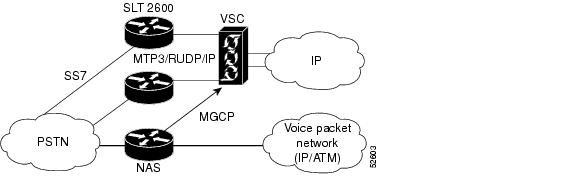
As part of a complete Cisco Systems end-to-end solution, the Cisco SLT enables Service Providers to reliably transport SS7 protocols across an IP network. The Cisco SLT uses the Cisco Internetworking Operating System SS7 Cisco SLT feature set, providing reliable interoperability with the MGC.
The Cisco SLT uses Cisco Reliable User Datagram Protocol (RUDP) to backhaul, or transport, upper-layer SS7 protocols across an IP network. Figure 1 shows a typical Cisco SLT network.
Figure 1 Cisco SLT Network
The Cisco SLT supports the following:
•
•
•
•
•
•
The Cisco SLT supports the following Message Transfer Part level 1 (MTP 1) functions:
•
•
The Cisco SLT supports the following Message Transfer Part level 2 (MTP 2) functions:
•
•
•
•
•
•
•
•
•
•
•
Cisco Session Manager
The session manager software manages the communication sessions with the Cisco MGC. When the Cisco SLT is used with a redundant pair of controllers, the session manager maintains separate communication sessions with each controller in the pair. The session between the Cisco SLT and the active controller transports the SS7 traffic, while the session between the Cisco SLT and the standby controller provides backup.
The session manager uses RUDP to communicate between the Cisco SLT and the controller. RUDP is a simple, connection-oriented, packet-based transport protocol that is Cisco-proprietary and based on RFC 908 (Reliable Data Protocol) and RFC 1151(version 2 of the Reliable Data Protocol).
RUDP helps establish a reliable connection between a client and a server and provides flow and congestion control. The term client refers to the peer that initiates the connection and the term server refers to the peer that listened for the connection. At each end, the connection is made using the IP address of the peer and a specified User Datagram Protocol (UDP) port.
In combination with this application specific version of the Cisco IOS, the Cisco SLT hardware component leverages the widely deployed Cisco 2611 Multiservice Access Router. The Cisco 2611 has an RISC CPU architecture providing high performance routing. The Cisco 2600 series routers meet service provider's critical physical requirements for equipment depth fitting right alongside transmission equipment on standard 12 inch deep with a 1 Rack-unit height. NEBs compliance is assured by using the NEBs/ETSI Kit included with the TC -SLT. Common Language Equipment Identification (CLEI) coding is provided for easy identification and tracking of central-office equipment. Internal DC, or AC power supplies or a redundant AC power supply adapter options are available.
Specifically, when used for Cisco SLT applications, the modular Cisco 2611 dual Ethernet port router can be configured with dual serial as well as the Multiflex interface cards with integrated E1 DSUs or T1 CSU/DSUs WAN interface cards. These interface cards permit fast servicing as Field Replaceable Units (FRUs). For additional flexibility the Multiflex interface cards may also be ordered with a dual-port Drop and Insert capability.
Interface Card
When used with the Cisco 2611, Cisco 2611XM, Cisco 2651, or Cisco 2651XM, the T1/E1 Multiflex interface cards provide a highly manageable and reliable one-box solution for Central Offices. These Multiflex cards offer the following features:
•
•
•
•
•
For additional information about the T1/E1 multiflex trunk interface cards, see Cisco WAN Interface Cards Hardware Installation Guide.
The dual-port serial WAN interface cards feature the Cisco compact high-density Smart Serial connector to support a wide variety of electrical interfaces when used with the appropriate transition cables. Ports on each card can be configured individually to support a variety of synchronous or asynchronous protocols. The high-speed WIC-2T supports port speeds up to 2.048 Mbps.
The single serial port WIC-1T supports synchronous-only connections using the Cisco 5-in-1 connector. It should be noted this card does not use the same transition cables as the WIC-2T.
Cisco 2611 and Cisco 2651 SLT
The Cisco SLT is supported on legacy Cisco 2611 and Cisco 2651 platforms. Refer to the End of Sale Announcement for Cisco 2600 (Non XM) VPN Bundles document on Cisco.com.
Cisco 2611XM and Cisco 2651XM SLT
The Cisco 2600XM multiservice routers are based on the current Cisco 2600 platform architecture and extend system performance by increasing default platform memory. The new XM functionality provides the same proven technology of the current Cisco 2600 Series platforms, including Cisco IOS software mainline feature support and the modularity of Network Modules (NMs), WAN Interface Cards (WICs) and Advanced Integration Modules (AIMs).
The Cisco 2611XM and Cisco 2651XM support FastEthernet interfaces and contain a common motherboard across the Cisco 2600XM product line. The Cisco 2600XM uses Synchronous Dynamic RAM (SDRAM) memory, rather than the older extended data output (EDO) memory that was used in the Cisco 2611 and Cisco 2651 platforms, which allows improvement in packet throughput.
Current Cisco SLT software automatically downloads the correct SS7 micropatch to migrate from the Cisco 2600-based SLT to the Cisco 2600XM-based SLT. The Cisco 2611XM and Cisco 2651XM use the same Motorola MPC860 processor as the Cisco 2611 and Cisco 2651 platforms and run at the same processor clock speeds.
The existing supported Cisco IOS software image for Cisco SLTs (c2600-ipss7-mz) operates on the Cisco 2611XM and Cisco 2651XM with no user changes required.
The Cisco 2611XM and Cisco 2651XM platforms are backwards compatible with the following Cisco SLT features:
•
•
•
•
•
•
Cisco AS5350 and Cisco AS5400 Integrated SLT
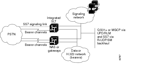
The integrated SLT pulls existing Cisco distributed MTP SS7 signaling architecture functionality—previously available only on Cisco 2600-based SLTs—directly onto a single Cisco AS5350 or Cisco AS5400 gateway. Like the Cisco 2600-based SLT, the integrated SLT on a Cisco AS5350 or Cisco AS5400 backhauls upper-layer SS7 protocols across an IP network using RUDP, terminating the MTP1 and MTP2 layers of the SS7 protocol stack at the MGC or Cisco PGW2200.
Using the 2-, 4-, or 8-PRI dial feature card (DFC) or the CT3 (28-PRI) DFC card, the integrated Cisco SLT is designed for small points of presence (POPs) that require only one or two network access servers (NASs) or Voice-Over-IP (VoIP) gateways as part of a dial or VoIP solution.
When the Integrated SLT feature is implemented, a Cisco AS5350 or Cisco AS5400 functions as an SS7 signaling data link terminal and as a NAS, voice gateway, or both when universal ports are used. Figure 2 shows a typical integrated SLT configuration.
Figure 2 Integrated SLT Architecture
The existing supported Cisco IOS software image for Cisco SLTs (c2600-ipss7-mz) operates on the Cisco 2611XM and Cisco 2651XM with no user changes required.
For more information about the integrated Cisco SLT, refer to the Integrated Signaling Link Terminal feature document on Cisco.com.
How to Configure the Cisco SLT
To configure the Cisco SLT for the Cisco 2611, complete the following:
•
•
Note
•
•
•
•
•
•
Note
Note
Note
Configuring the Basic Parameters
To configure the basic parameters of the Cisco SLT, complete the following steps;
SUMMARY STEPS
1.
2.
3.
4.
5.
6.
7.
8.
9.
10.
11.
12.
DETAILED STEPS
This completes the basic Cisco SLT configuration.
Configuring the Physical Interfaces
The following section contains information about how to configure T1 or E1 multiflex trunk interfaces for the Cisco SLT.
Cisco SLT T1/E1 Multiflex Trunk Interfaces Overview
The T1/E1 multiflex trunk interface cards are dual-mode T1 or E1 interfaces in a VWIC (Voice/WAN Interface card) form for voice, data, and integrated voice and data applications. They support the SS7 Cisco SLT function, as do serial WICs.
The T1/E1 VWIC supports the following T1/E1 functionality:
•
•
•
For additional information about the T1/E1 multiflex trunk interface cards, refer to the Cisco WAN Interface Cards Hardware Installation Guide.
Configuring T1/E1 Multiflex Trunk Interfaces
The following steps show how to configure T1/E1 multiflex trunk interfaces.
Note
For information about configuring other types of WICs, refer to the Cisco WAN Interface Cards Hardware Installation Guide.
SUMMARY STEPS
1.
2.
3.
4.
5.
6.
7.
8.
9.
10.
DETAILED STEPS
Verifying T1/E1 Multiflex Trunk Interface Configuration
To verify the initial T1/E1 trunk interface configuration, follow these steps.
SUMMARY STEPS
1.
2.
3.
4.
5.
DETAILED STEPS
The following is sample output from the show controllers e1 command. Important information appears in bold:
Router# show controllers e1E1 0/2 is up.Applique type is Channelized E1 - balancedCablelength is UnknownNo alarms detected.Version info Firmware: 19990702, FPGA: 6Framing is CRC4, Line Code is HDB3, Clock Source is Line.Data in current interval (599 seconds elapsed):0 Line Code Violations, 0 Path Code Violations0 Slip Secs, 0 Fr Loss Secs, 0 Line Err Secs, 0 Degraded Mins0 Errored Secs, 0 Bursty Err Secs, 0 Severely Err Secs, 0 Unavail SecsTotal Data (last 10 15 minute intervals):435334 Line Code Violations, 1 Path Code Violations,8 Slip Secs, 69 Fr Loss Secs, 9 Line Err Secs, 0 Degraded Mins,8 Errored Secs, 0 Bursty Err Secs, 0 Severely Err Secs, 69 Unavail SecsE1 0/3 is down.Applique type is Channelized E1 - balancedCablelength is UnknownFar End Block Errors DetectedReceiver has loss of signal.Version info Firmware: 19990702, FPGA: 6Framing is CRC4, Line Code is HDB3, Clock Source is Line.Data in current interval (602 seconds elapsed):0 Line Code Violations, 0 Path Code Violations0 Slip Secs, 602 Fr Loss Secs, 0 Line Err Secs, 0 Degraded Mins0 Errored Secs, 0 Bursty Err Secs, 0 Severely Err Secs, 603 Unavail SecsTotal Data (last 10 15 minute intervals):0 Line Code Violations, 0 Path Code Violations,0 Slip Secs, 9000 Fr Loss Secs, 0 Line Err Secs, 0 Degraded Mins,0 Errored Secs, 0 Bursty Err Secs, 0 Severely Err Secs, 9000 Unavail SecsThe following is sample output from the show controllers t1 command. Important information is shown in bold:
Router# show controllers t1T1 0/0 is up.Applique type is Channelized T1Cablelength is short 133No alarms detected.Version info Firmware: 19990702, FPGA: 6Framing is ESF, Line Code is B8ZS, Clock Source is Line.Data in current interval (608 seconds elapsed):136066 Line Code Violations, 778727 Path Code Violations567 Slip Secs, 0 Fr Loss Secs, 608 Line Err Secs, 0 Degraded Mins0 Errored Secs, 0 Bursty Err Secs, 0 Severely Err Secs, 608 Unavail SecsTotal Data (last 10 15 minute intervals):4286812 Line Code Violations, 11478885 Path Code Violations,7734 Slip Secs, 69 Fr Loss Secs, 8996 Line Err Secs, 0 Degraded Mins,0 Errored Secs, 0 Bursty Err Secs, 0 Severely Err Secs, 9000 Unavail SecsTo find out about channel groups configured as virtual serial interfaces, enter the show interface serial slot/port:subinterface command. Important information is shown in bold in the following sample output:
Router# show interface serial 0/0:0Serial0/0:0 is reset, line protocol is downHardware is PowerQUICC SerialMTU 1500 bytes, BW 56 Kbit, DLY 20000 usec,reliability 253/255, txload 1/255, rxload 1/255Encapsulation SS7 MTP2, loopback not setKeepalive set (10 sec)Last input never, output 00:12:22, output hang neverLast clearing of "show interface" counters neverInput queue: 0/75/0 (size/max/drops); Total output drops: 0Queueing strategy: weighted fairOutput queue: 0/1000/64/0 (size/max total/threshold/drops)Conversations 0/0/256 (active/max active/max total)Reserved Conversations 0/0 (allocated/max allocated)5 minute input rate 0 bits/sec, 0 packets/sec5 minute output rate 0 bits/sec, 0 packets/sec0 packets input, 0 bytes, 0 no bufferReceived 0 broadcasts, 0 runts, 0 giants, 0 throttles1437 input errors, 2 CRC, 31 frame, 0 overrun, 0 ignored, 1404 abort128055 packets output, 512220 bytes, 0 underruns0 output errors, 0 collisions, 2 interface resets0 output buffer failures, 0 output buffers swapped out1 carrier transitionsTimeslot(s) Used:1, Transmitter delay is 0 flagsThe following sample output shows information about the virtual serial interface:
Router# show controllers serial 0/2:0Interface Serial0/2:0Hardware is PowerQUICC MPC860idb at 0x81143590, driver data structure at 0x81145474SCC Registers:General [GSMR]=0x2:0x00000033, Protocol-specific [PSMR]=0x8Events [SCCE]=0x0200, Mask [SCCM]=0x001F, Status [SCCS]=0x02Transmit on Demand [TODR]=0x0, Data Sync [DSR]=0x7E7EInterrupt Registers:Config [CICR]=0x00367F80, Pending [CIPR]=0x04000246Mask [CIMR]=0x60240000, In-srv [CISR]=0x00000000Command register [CR]=0xD40Port A [PADIR]=0x00F0, [PAPAR]=0x25F0[PAODR]=0x0000, [PADAT]=0x5A4FPort B [PBDIR]=0x0000F, [PBPAR]=0x0000E[PBODR]=0x00000, [PBDAT]=0x37FFDPort C [PCDIR]=0x00C, [PCPAR]=0xA00[PCSO]=0x000, [PCDAT]=0x5F2, [PCINT]=0xFFFReceive Ringrmd(68012930): status 9000 length 6 address 2DA22E4rmd(68012938): status 9000 length 6 address 2DA3AA4rmd(68012940): status 9000 length 6 address 2DA1E24rmd(68012948): status 9000 length 6 address 2DA27A4rmd(68012950): status 9000 length 6 address 2DA5724rmd(68012958): status 9000 length 6 address 2DA14A4rmd(68012960): status 9000 length 6 address 2DA5264rmd(68012968): status 9000 length 6 address 2DA4684rmd(68012970): status 9000 length 6 address 2DA4424rmd(68012978): status 9000 length 6 address 2DA1964rmd(68012980): status 9000 length 6 address 2DA4B44rmd(68012988): status 9000 length 6 address 2DA60A4rmd(68012990): status 9000 length 6 address 2DA2544rmd(68012998): status 9000 length 6 address 2DA3124rmd(680129A0): status 9000 length 6 address 2DA0FE4rmd(680129A8): status B000 length 6 address 2DA3844Transmit Ringtmd(680129B0): status DC00 length 4 address 2AD9EA8tmd(680129B8): status DC00 length 4 address 2AD7568tmd(680129C0): status DC00 length 4 address 2ADA428tmd(680129C8): status DC00 length 4 address 2ADA6E8tmd(680129D0): status DC00 length 4 address 2AD7DA8tmd(680129D8): status DC00 length 4 address 2AD5468tmd(680129E0): status DC00 length 4 address 2AD8328tmd(680129E8): status DC00 length 4 address 2AD85E8tmd(680129F0): status DC00 length 4 address 2AD5CA8tmd(680129F8): status CE00 length 4 address 2AD8B68tmd(68012A00): status DC00 length 4 address 2AD8E28tmd(68012A08): status DC00 length 4 address 2AD64E8tmd(68012A10): status DC00 length 4 address 2AD67A8tmd(68012A18): status DC00 length 4 address 2AD9668tmd(68012A20): status DC00 length 4 address 2AD9928tmd(68012A28): status FC00 length 4 address 2AD6FE8SPI Mode [SPMODE]=0xF70, Events [SPIE]=0x0Mask [SPIM]=0x0, Command [SPCOM]=0x0SI Mode [SIMODE]=0x80408040, Global [SIGMR]=0xECmnd [SICMR]=0x0, Stat [SISTR]=0x0SI Clock Route [SICR]=0x00004040SCC GENERAL PARAMETER RAM (at 0x68013D00)Rx BD Base [RBASE]=0x2930, Fn Code [RFCR]=0x18Tx BD Base [TBASE]=0x29B0, Fn Code [TFCR]=0x18Max Rx Buff Len [MRBLR]=1548Rx State [RSTATE]=0x0, BD Ptr [RBPTR]=0x2970Tx State [TSTATE]=0x188920A3, BD Ptr [TBPTR]=0x2A08SCC SS7 PARAMETER RAM (at 0x68013D38)CRC Preset [C_PRES]=0xFFFF, Mask [C_MASK]=0xF0B8Error-free SUs [EFSUC] = 22927Max frm len [MFLR] = 278Erm [ERM] = 0x0,N [NOCTETS] = 16, N_cnt [NOCTETS_CNT] = 12, T [ERM_THRESH] = 64,D [ERM_EFSUS] = 256, D_cnt [ERM_EFSUS_CNT] = 97SS7 options [SS7_OPT] = 0x10FFilter masks [MASK1] = 0xFFFFFFFF, [MASK2] = 0xFFbuffer size 1524PQUICC SCC specific errors:0 input aborts on receiving flag sequence0 throttles, 0 enables0 overruns0 transmitter underruns0 transmitter CTS lostsConfiguring Drop and Insert
To configure Drop and Insert (the TDM cross-connect function), complete the following steps.
SUMMARY STEPS
1.
2.
3.
4.
5.
6.
7.
8.
DETAILED STEPS
Configuring the Serial Interfaces
The following steps show how to configure 1T and 2T serial interfaces.
SUMMARY STEPS
1.
2.
3.
4.
5.
DETAILED STEPS
Configuring the Ethernet Interface
The Cisco SLT uses the built-in Ethernet interface for connection to the IP network that backhauls SS7 MSUs between the Cisco 2611 router and the MGC. Follow the steps below to configure the Ethernet interface.
SUMMARY STEPS
1.
2.
3.
4.
5.
6.
DETAILED STEPS
Verifying the Ethernet Interface Configuration
To verify the Ethernet interface configuration, enter the show interface ethernet 0/0 privileged EXEC command. The following text is sample output from the command:
Router# show interface ethernet 0/0Ethernet0/0 is up, line protocol is upHardware is AmdP2, address is 0050.7337.5100 (bia 0050.7337.5100)Internet address is 255.251.111.6/24MTU 1500 bytes, BW 10000 Kbit, DLY 1000 usec,reliability 255/255, txload 1/255, rxload 1/255Encapsulation ARPA, loopback not setKeepalive set (10 sec)ARP type: ARPA, ARP Timeout 04:00:00Last input 00:00:00, output 00:00:00, output hang neverLast clearing of "show interface" counters 10:00:36Queueing strategy: fifoOutput queue 0/40, 0 drops; input queue -196/75, 0 drops5 minute input rate 3000 bits/sec, 5 packets/sec5 minute output rate 2000 bits/sec, 4 packets/sec45891 packets input, 3234949 bytes, 0 no bufferReceived 1593 broadcasts, 0 runts, 0 giants, 0 throttles0 input errors, 0 CRC, 0 frame, 0 overrun, 0 ignored0 input packets with dribble condition detected61546 packets output, 3728838 bytes, 0 underruns(518/2091/0)0 output errors, 2609 collisions, 3 interface resets0 babbles, 0 late collision, 875 deferred0 lost carrier, 0 no carrier0 output buffer failures, 0 output buffers swapped outConfiguring the Fast Ethernet Interface
The Cisco 2611XM, Cisco 2651, and Cisco 2651XM SLTs use the built-in Fast Ethernet interface to connect to the IP network that backhauls SS7 Message Signal Units (MSUs) between the Cisco SLT and the media gateway controller or Cisco PGW2200. The Cisco 2611XM, Cisco 2651, and Cisco 2651XM routers have two Fast Ethernet ports which need to be configured instead of the two Ethernet interface ports found on the Cisco 2611-based Cisco SLT.
To configure the Fast Ethernet interface, use the following commands.
SUMMARY STEPS
1.
2.
3.
4.
5.
6.
Verifying the Fast Ethernet Interface Configuration
To verify the Fast Ethernet interface configuration, enter the show interface fastethernet privileged EXEC command. The following example shows statistics for port 0/0:
SLT-2651# sh interface fastethernet 0/0FastEthernet0/0 is up, line protocol is upHardware is AmdFE, address is 0003.e38d.db20 (bia 0003.e38d.db20)Description:This port used for Signalling BackhaulInternet address is 10.30.18.41/24MTU 1500 bytes, BW 100000 Kbit, DLY 100 usec,reliability 255/255, txload 1/255, rxload 1/255Encapsulation ARPA, loopback not setKeepalive set (10 sec)Full-duplex, 100Mb/s, 100BaseTX/FXARP type:ARPA, ARP Timeout 04:00:00Last input 00:00:00, output 00:00:00, output hang neverLast clearing of "show interface" counters neverQueueing strategy:fifoOutput queue 0/40, 0 drops; input queue 0/75, 0 drops5 minute input rate 0 bits/sec, 0 packets/sec5 minute output rate 0 bits/sec, 0 packets/sec775355 packets input, 55085581 bytesReceived 7194 broadcasts, 0 runts, 0 giants, 0 throttles0 input errors, 0 CRC, 0 frame, 0 overrun, 0 ignored0 watchdog0 input packets with dribble condition detected716414 packets output, 56748158 bytes, 0 underruns(0/0/0)0 output errors, 0 collisions, 1 interface resets0 babbles, 0 late collision, 0 deferred0 lost carrier, 0 no carrier0 output buffer failures, 0 output buffers swapped outConfiguring the Session Manager and RUDP
The session manager and the RUDP are responsible for managing the communication sessions with the MGCs. Regardless of the number of SS7 links that the MGC activates on the Cisco 2611, the router maintains only one session manager session with each of the MGC devices.
Note
To configure the session for establishing communications with the Cisco MGC, use the following commands. You can define just one session or as many as two sessions.
SUMMARY STEPS
1.
2.
3.
4.
5.
6.
7.
8.
DETAILED STEPS
Verifying the Session Manager and RUDP Configuration
To verify the session manager and RUDP configuration, use the following commands
SUMMARY STEPS
1.
2.
3.
4.
DETAILED STEPS
Configuring the MTP2 Variant
SS7 MTP2 supports four variants: Telcordia (formerly Bellcore), ITU, NTT (Japan), and TTC (Japan Telecom). The parameters under one variant have different meanings, purposes, and ranges in another.
See the following command references for the appropriate MTP 2 variant commands and the parameters:
Note
The channel to be configured must be out of service at the MGC before the variant or the variant configuration can be changed.
Note
SUMMARY STEPS
1.
2.
3.
4.
5.
6.
7.
8.
9.
10.
DETAILED STEPS
Configuring the Media Gateway Controller
The MGC provides call control. Once the Cisco SLT is configured, you must configure the point codes, linksets, SS7 signaling links, and the associated MTP 2 parameters on the MGC.
Each SS7 link defined on the MGC is considered a logical channel, and each logical channel corresponds to a physical interface on the Cisco 2611. You can define two SS7 links (logical channels) from the MGC to a Cisco 2600 series router. The logical channels defined on the TCS map to the physical serial interfaces on the router from right to left, as follows:
•
•
•
Table 1shows some examples of how different signaling termination channels might map to interface positions.
For more information about configuring the MGC software, refer to the Cisco Media Gateway Controllers documentation on Cisco.com.
Troubleshooting Tips
The following are the show and clear commands that you can use to maintain the Cisco SLT
Configuration Examples for the Cisco SLT
This section provides the following configuration examples:
•
•
•
•
Basic Cisco SLT Configuration Parameters Example
The following is an example of the initial configuration dialog system prompt. In this example, y (yes) has been entered in order to begin the configuration process:
Would you like to enter the initial configuration dialog? [yes/no]: yBasic management setup provides only enough connectivity for management of the system. The following is an example of an extended setup prompt that asks you to configure each interface on the system. In this example, y (yes) has been entered to begin basic management setup:
Would you like to enter basic management setup?
[yes/no]: y
Configuring global parameters:The following is an example a host name system prompt. In this example, the host name is for the Cisco 2611 router:
Enter host name [Router]: 2611_nameThe following is an example of the enable secret password system prompt. The enable secret is a password used to protect access to privileged EXEC and configuration modes. This password becomes encrypted in the configuration and cannot be seen when viewing the configuration:
Enter enable secret: enable_secretThe following is an example of the enable password that is different from the enable secret password. This password is not encrypted and can be seen when viewing the configuration. The enable password is used when you do not specify an enable secret password.
Enter enable password: enable_passwordThe following is an example of the virtual terminal password, which prevents unauthenticated access to the Cisco SLT through ports other than the console port. The virtual terminal password is used to protect access to the router over a network interface.
Enter virtual terminal password: vt_passwordThe following is an example of how to answer the configure the SNMP parameters system prompt:
Configure SNMP Network Management? [yes]: yesCommunity string [public]:The following is an example of the interface name used to connect to the management network:
Current interface summaryController Timeslots D-Channel Configurable modes StatusT1 0/2 24 23 pri/channelized Administratively upT1 0/3 24 23 pri/channelized Administratively upAny interface listed with OK? value "NO" does not have a valid configurationInterface IP-Address OK? Method Status ProtocolEthernet0/0 unassigned NO unset up upSerial0/0 unassigned NO unset down downEthernet0/1 unassigned NO unset up downSerial0/1 unassigned NO unset down downEnter interface name used to connect to the management network from the above interface summary: Ethernet0/0The following is an example of how to configure the Ethernet interface:
Configuring interface Ethernet0/0:Configure IP on this interface? [yes]: yThe following is an example of how to specify the IP address and the subnet mask for the interface:
IP address for this interface: 10.1.1.5Subnet mask for this interface [255.0.0.0]: 255.255.0.0Class A network is 10.0.0.0, 16 subnet bits; mask is /16The following is an example of how to save the configuration to NVRAM and exit the initial configuration mode.
The following configuration command script was created:hostname aladdinenable secret 5 $1$0gLU$vLK1YHrMcianH5oVWFJNP/enable password lablabline vty 0 4password labno snmp-server!no ip routing!interface Ethernet0/0no shutdownip address 10.1.1.5 255.255.0.0!interface Serial0/0shutdownno ip address!interface Ethernet0/1shutdownno ip address!interface Serial0/1shutdownno ip address!end[0] Go to the IOS command prompt without saving this config.[1] Return back to the setup without saving this config.[2] Save this configuration to nvram and exit.Enter your selection [2]: 2Building configuration...Use the enabled mode 'configure' command to modify this configuration.Press RETURN to get started!Cisco SLT T1 Configuration Example
The following example shows the configuration of the Cisco SLT with a T1 interface card.
version 12.0no service padservice timestamps debug datetime msecservice timestamps log datetime msec localtimeno service password-encryption!hostname Router_T1!logging buffered 4096 debugging!ip subnet-zero!Extended SuperFrame (ESF) framing and binary-8 zero substitution (B8ZS) are configured on the T1 0/0 controller. For these settings, the defaults are usually sufficient and only need to be changed because the service provider requires it.
Because this is a short-haul link, the cable length is specified as short.controller T1 0/0framing esflinecode b8zscablelength short 133The channel-group controller configuration command creates a channel group 0 that occupies a single time slot.
channel-group 0 timeslots 24!controller T1 0/1framing esftdm-group 2 timeslots 1-23!process-max-time 200!Ethernet 0/0 provides the IP connection for backhauling SS7 information between the Cisco 2600 series router and the MGC.
interface Ethernet0/0ip address 255.1.1.6no ip directed-broadcastno ip mroute-cacheno cdp enable!The channel-group command creates a logical serial interface that corresponds to the slot and port location of the T1 interface, and to the channel group number of 0.
interface Serial0/0:0no ip addressno ip directed-broadcast!interface Ethernet0/1no ip addressno ip directed-broadcastno ip mroute-cache!ip classlessno ip http server!The SS7 commands all use the default settings. This is especially important for the session timers, which should not be changed except at the instruction of Cisco technical assistance. Two sessions are configured here.
ss7 set failover-timer 3ss7 session-0 address 255.1.0.2 8060 255.1.1.6 8060ss7 session-0 retrans_t 600ss7 session-0 cumack_t 300ss7 session-0 kp_t 2000ss7 session-0 m_retrans 2ss7 session-0 m_cumack 3ss7 session-0 m_outseq 3ss7 session-0 m_rcvnum 32ss7 session-1 address 255.1.0.1 8061 255.1.1.6 8061ss7 session-1 retrans_t 600ss7 session-1 cumack_t 300ss7 session-1 kp_t 2000ss7 session-1 m_retrans 2ss7 session-1 m_cumack 3ss7 session-1 m_outseq 3ss7 session-1 m_rcvnum 32!line con 0exec-timeout 0 0transport input noneline aux 0line vty 0 4exec-timeout 0 0password lablogin!endThe ss7 mtp2-variant command determines the MTP 2 variant on each channel.
ss7 mtp2-variant NTT 0ss7 mtp2-variant NTT 1ss7 mtp2-variant Bellcore 2ss7 mtp2-variant Bellcore 3Cisco SLT E1 with Drop and Insert Configuration Example
The following example shows configuration of the Cisco SLT with an E1 voice/WAN interface card that has Drop-and-Insert capabilities.
version 12.0no service padservice timestamps debug datetime msecservice timestamps log datetime msec localtimeno service password-encryption!hostname Router_E1!logging buffered 4096 debugging!ip subnet-zero!The channel-group controller configuration commands create channel groups 0, each of which occupies a single time slot. The TDM groups use the rest of the time slots.
!controller E1 0/0channel-group 0 timeslots 16tdm-group 1 timeslots 1-15,17-31!controller E1 0/1clock source internaltdm-group 1 timeslots 1-15,17-31!controller E1 0/2channel-group 0 timeslots 16!controller E1 0/3!process-max-time 200!Ethernet 0/0 provides the IP connection for backhauling SS7 information between the Cisco 2600 series router and the MGC.
interface Ethernet0/0ip address 10.1.1.6no ip directed-broadcastno ip mroute-cacheno cdp enable!The channel-group command creates two logical serial interfaces that correspond to the slot and port locations of the E1 interfaces, and to the channel group number of 0.
interface Serial0/0:0no ip addressno ip directed-broadcastno keepalive!interface Ethernet0/1no ip addressno ip directed-broadcastno ip mroute-cache!interface Serial0/2:0no ip addressno ip directed-broadcastno keepalive!ip classlessno ip http server!The connect command links the two VWIC ports for Drop and Insert.connect my_connection E1 0/0 1 E1 0/1 1!The SS7 commands all use the default settings. This is especially important for the session timers, which should not be changed except at the direction of Cisco technical assistance. Two sessions are configured here.
ss7 set failover-timer 3ss7 session-0 address 10.1.0.2 8060 10.1.1.6 8060ss7 session-0 retrans_t 600ss7 session-0 cumack_t 300ss7 session-0 kp_t 2000ss7 session-0 m_retrans 2ss7 session-0 m_cumack 3ss7 session-0 m_outseq 3ss7 session-0 m_rcvnum 32ss7 session-1 address 10.1.0.1 8061 10.1.1.6 8061ss7 session-1 retrans_t 600ss7 session-1 cumack_t 300ss7 session-1 kp_t 2000ss7 session-1 m_retrans 2ss7 session-1 m_cumack 3ss7 session-1 m_outseq 3ss7 session-1 m_rcvnum 32!line con 0exec-timeout 0 0transport input noneline aux 0line vty 0 4exec-timeout 0 0password lablogin!endThe ss7 mtp2-variant command determines the MTP 2 variant on each channel.
ss7 mtp2-variant NTT 0ss7 mtp2-variant NTT 1ss7 mtp2-variant Bellcore 2ss7 mtp2-variant Bellcore 3Session Manager and RUDP Configuration Example
The following example shows information about an SS7 session manager session:
Router# show ss7 sm sessionSession[0]: Remote Host 255.251.250.252:8060, Local Host 255.251.251.252:8060retrans_t = 600cumack_t = 300kp_t = 2000m_retrans = 2m_cumack = 3m_outseq = 3m_rcvnum = 32Session[1]: Remote Host 255.251.250.253:8060, Local Host 255.251.251.252:8061retrans_t = 600cumack_t = 300kp_t = 2000m_retrans = 2m_cumack = 3m_outseq = 3m_rcvnum = 32The following example shows information about the failover timer setting:
Router# show ss7 sm setSession Manager Setfailover timer = 3 secondsThe following example shows session manager statistics:
Router# show ss7 sm stats-------------------- Session Manager --------------------Session Manager state = SESSION SET STATE-ACTIVESession Manager Up count = 1Session Manager Down count = 0lost control packet count = 0lost PDU count = 0failover timer expire count = 0invalid_connection_id_count = 0Session[0] statistics SM SESSION STATE-STANDBY:Session Down count = 0Open Retry count = 0Total Pkts receive count = 1Active Pkts receive count = 0Standby Pkts receive count = 1PDU Pkts receive count = 0Unknown Pkts receive count = 0Pkts send count = 0Pkts requeue count = 0-Pkts window full count = 0-Pkts resource unavail count = 0-Pkts enqueue fail count = 0PDUs dropped (Large) = 0PDUs dropped (Empty) = 0RUDP Not Ready Errs = 0RUDP Connection Not Open = 0RUDP Invalid Conn Handle = 0RUDP Unknown Errors = 0RUDP Unknown Signal = 0NonActive Receive count = 0Session[1] statistics SM SESSION STATE-ACTIVE:Session Down count = 0Open Retry count = 0Total Pkts receive count = 2440Active Pkts receive count = 1Standby Pkts receive count = 0PDU Pkts receive count = 2439Unknown Pkts receive count = 0Pkts send count = 2905Pkts requeue count = 0-Pkts window full count = 0-Pkts resource unavail count = 0-Pkts enqueue fail count = 0PDUs dropped (Large) = 0PDUs dropped (Empty) = 0RUDP Not Ready Errs = 0RUDP Connection Not Open = 0RUDP Invalid Conn Handle = 0RUDP Unknown Errors = 0RUDP Unknown Signal = 0NonActive Receive count = 0Additional References
For additional information related to the Cisco SLT feature, refer to the following references:
•
•
Related Documents
For additional information on how to install and configure a Cisco 2600 and for information about the VWIC interfaces, refer to the following documentation on Cisco.com.
Standards
No new or modified standards are supported by this feature, and support for existing standards has not been modified by this feature.
—
MIBs
No new or modified MIBs are supported by this feature, and support for existing MIBs has not been modified by this feature.
To obtain lists of supported MIBs by platform and Cisco IOS release, and to download MIB modules, go to the Cisco MIB website on Cisco.com at the following URL:
http://www.cisco.com/public/sw-center/netmgmt/cmtk/mibs.shtml
To locate and download MIBs for selected platforms, Cisco IOS releases, and feature sets, use Cisco MIB Locator found at the following URL:
http://tools.cisco.com/ITDIT/MIBS/servlet/index
If Cisco MIB Locator does not support the MIB information that you need, you can also obtain a list of supported MIBs and download MIBs from the Cisco MIBs page at the following URL:
http://www.cisco.com/public/sw-center/netmgmt/cmtk/mibs.shtml
To access Cisco MIB Locator, you must have an account on Cisco.com. If you have forgotten or lost your account information, send a blank e-mail to cco-locksmith@cisco.com. An automatic check will verify that your e-mail address is registered with Cisco.com. If the check is successful, account details with a new random password will be e-mailed to you. Qualified users can establish an account on Cisco.com by following the directions found at this URL:
RFCs
No new or modified RFCs are supported by this feature, and support for existing RFCs has not been modified by this feature.
—
Technical Assistance
Command Reference
This section documents modified commands. All other commands used with this feature are documented in the Cisco IOS Release 12.2(xx) command reference publications.
clear rudpv0 statistics
To clear the counters that track RUDP statistics, enter the clear rudpv0 statistics command in privileged EXEC mode.
clear rudpv0 statistics
Syntax Description
This command has no arguments or keywords.
Defaults
The statistical information accumulates.
Command Modes
Privileged EXEC
Command History
Examples
The following example shows how to clear RUDP statistics on a Cisco 2611 (Cisco SLT):
clear rudpv0 statisticsRelated Commands
clear ss7 sm stats
To clear the counters that track session manager statistics, use the clear ss7 sm stats command in privileged EXEC mode.
clear ss7 sm stats
Syntax Description
This command has no arguments or keywords.
Defaults
The statistical information accumulates
Command Modes
Privileged EXEC
Command History
Examples
The following example shows how to clear session manager statistics on a Cisco 2611:
clear ss7 sm statsRelated Commands
show ss7 sm stats
Displays session manager information about number of packets queued, received, and so forth.
debug rudpv0 application
To enable SS7 Reliable User Datagram Protocol (RUDP) application debugging, enter the debug rudpv0 application privileged EXEC command. The no form of this command disables debugging output.
debug rudpv0 application
no debug rudpv0 application
Warning
Syntax Description
This command has no arguments or keywords.
Command History
Usage Guidelines
The output for this command shows the sequence numbers of segments as they are being passed to the upper layer protocol.
Examples
The following is an example of debug rudpv0 application command output:
*Mar 1 00:41:09.387: Turning application debugging on*Mar 1 00:41:09.395: Send to appl, seq 204*Mar 1 00:41:13.722: Send to appl, seq 205*Mar 1 00:41:23.631: Send to appl, seq 206*Mar 1 00:41:37.225: Send to appl, seq 207*Mar 1 00:41:37.225: Send to appl, seq 208*Mar 1 00:41:37.225: Send to appl, seq 209*Mar 1 00:41:39.404: Send to appl, seq 210*Mar 1 00:41:39.444: Send to appl, seq 211*Mar 1 00:41:48.632: Send to appl, seq 212debug rudpv0 performance
To view information about sent and received SS7 Reliable User Datagram Protocol (RUDP) packets, enter the debug rudpv0 performance privileged EXEC command. The no form of this command disables debugging output.
debug rudpv0 performance
no debug rudpv0 performance
Syntax Description
This command has no arguments or keywords.
Command History
Usage Guidelines
The output for this command shows the average number of segments that are sent and received per second for all RUDP connections combined. The "Sent" and "Rcvd" counts report the total number of segments (both internal RUDP segments and data segments) averaged over the time since the last issue of the clear rudpv0 statistics command or the last reboot.
The "Data Bytes" and packet counts are averaged only over the number of segments when there is actual data traffic flowing. For example, sent keepalive segments do not affect these counts.
Examples
The following is an example of debug rudpv0 performance command output:
Router# debug rudpv0 performance*Mar 1 01:12:34.065: Turning performance debugging on*Mar 1 01:12:41.817:*Mar 1 01:12:41.817: Sent: Pkts 1, Data Bytes 118, Data Pkts 1*Mar 1 01:12:41.817: Rcvd: Pkts 1, Data Bytes 47, Data Pkts 1*Mar 1 01:12:41.817: Discarded: 0, Retransmitted 0*Mar 1 01:12:41.817:*Mar 1 01:12:51.846:*Mar 1 01:12:51.846: Sent: Pkts 1, Data Bytes 118, Data Pkts 1*Mar 1 01:12:51.846: Rcvd: Pkts 1, Data Bytes 47, Data Pkts 1*Mar 1 01:12:51.846: Discarded: 0, Retransmitted 0*Mar 1 01:12:51.846:*Mar 1 01:13:01.874:*Mar 1 01:13:01.874: Sent: Pkts 1, Data Bytes 118, Data Pkts 1*Mar 1 01:13:01.874: Rcvd: Pkts 1, Data Bytes 47, Data Pkts 1*Mar 1 01:13:01.874: Discarded: 0, Retransmitted 0*Mar 1 01:13:01.874:*Mar 1 01:13:11.907:*Mar 1 01:13:11.907: Sent: Pkts 1, Data Bytes 118, Data Pkts 1*Mar 1 01:13:11.907: Rcvd: Pkts 1, Data Bytes 47, Data Pkts 1*Mar 1 01:13:11.907: Discarded: 0, Retransmitted 0*Mar 1 01:13:11.907:*Mar 1 01:13:21.931:*Mar 1 01:13:21.931: Sent: Pkts 1, Data Bytes 118, Data Pkts 1*Mar 1 01:13:21.931: Rcvd: Pkts 1, Data Bytes 47, Data Pkts 1debug rudpv0 retransmit
To show information about SS7 Reliable User Datagram Protocol (RUDP) retransmit timer performance, enter the debug rudpv0 retransmit privileged EXEC command. The no form of this command disables debugging output.
debug rudpv0 retransmit
no debug rudpv0 retransmit
Warning
Syntax Description
This command has no arguments or keywords.
Command History
Usage Guidelines
The output for this command shows internal RUDP events that are involved in retransmitting segments.
Examples
The following is an example of debug rudpv0 retransmit command output:
Router# debug rudpv0 retransmit*Mar 1 01:14:21.405: Turning retransmit/softreset debugging on*Mar 1 01:14:21.633: Retrans timer, set to ack 67*Mar 1 01:14:22.647: Retrans timer, set to ack 45*Mar 1 01:14:23.636: Retrans timer, set to ack 46*Mar 1 01:14:23.636: Retrans timer, set to ack 68*Mar 1 01:14:25.640: Retrans timer, set to ack 47*Mar 1 01:14:25.644: Retrans timer, set to ack 69*Mar 1 01:14:27.639: Retrans timer, set to ack 48*Mar 1 01:14:27.643: Retrans timer, set to ack 70*Mar 1 01:14:29.642: Retrans timer, set to ack 49*Mar 1 01:14:29.646: Retrans timer, set to ack 71*Mar 1 01:14:31.645: Retrans timer, set to ack 50*Mar 1 01:14:31.649: Retrans timer, set to ack 72*Mar 1 01:14:33.649: Retrans timer, set to ack 51*Mar 1 01:14:33.653: Retrans timer, set to ack 73*Mar 1 01:14:35.648: Retrans timer, set to ack 52*Mar 1 01:14:35.652: Retrans timer, set to ack 74*Mar 1 01:14:37.203: Retrans timer, set to ack 53*Mar 1 01:14:37.655: Retrans timer, set to ack 75*Mar 1 01:14:39.210: Retrans timer, set to ack 56*Mar 1 01:14:39.659: Retrans timer, set to ack 76*Mar 1 01:14:41.209: Retrans timer, set to ack 57*Mar 1 01:14:41.662: Retrans timer, set to ack 77debug rudpv0 segment
To show information about segments being sent and received by the SS7 Reliable User Datagram Protocol (RUDP), enter the debug rudpv0 segment privileged EXEC command. The no form of this command disables debugging output.
debug rudpv0 segment
no debug rudpv0 segment
Warning
Syntax Description
This command has no arguments or keywords.
Command History
Usage Guidelines
The output for this command shows segments that are being sent and received by the RUDP and the control bits that are set in those segments. The number in parentheses is the length of the segment.
Examples
The following is an example of debug rudpv0 segment command output:
Router# debug rudpv0 segment*Mar 1 01:16:57.981: Turning segment debugging on*Mar 1 01:16:58.005: RUDP: Rcvd ACK 30..145 (4),*Mar 1 01:16:58.642: RUDP: Send NUL ACK 143..155 (4),*Mar 1 01:16:58.895: RUDP: Rcvd ACK 156..143 (4),*Mar 1 01:16:59.808: RUDP: Send NUL ACK 146..29 (4),*Mar 1 01:17:00.105: RUDP: Rcvd ACK 30..146 (4),*Mar 1 01:17:00.646: RUDP: Send NUL ACK 144..155 (4),*Mar 1 01:17:00.898: RUDP: Rcvd ACK 156..144 (4),*Mar 1 01:17:01.812: RUDP: Send NUL ACK 147..29 (4),*Mar 1 01:17:02.108: RUDP: Rcvd ACK 30..147 (4),*Mar 1 01:17:02.645: RUDP: Send NUL ACK 145..155 (4),*Mar 1 01:17:02.897: RUDP: Rcvd ACK 156..145 (4),*Mar 1 01:17:03.811: RUDP: Send NUL ACK 148..29 (4),*Mar 1 01:17:04.107: RUDP: Rcvd ACK 30..148 (4),*Mar 1 01:17:04.648: RUDP: Send NUL ACK 146..155 (4),*Mar 1 01:17:04.897: RUDP: Rcvd ACK 156..146 (4),*Mar 1 01:17:05.814: RUDP: Send NUL ACK 149..29 (4),*Mar 1 01:17:06.107: RUDP: Rcvd ACK 30..149 (4),*Mar 1 01:17:06.652: RUDP: Send NUL ACK 147..155 (4),*Mar 1 01:17:06.896: RUDP: Rcvd ACK 156..147 (4),*Mar 1 01:17:07.188: RUDP: Rcvd ACK 156..147 (24),*Mar 1 01:17:07.192: RUDP: Rcvd ACK 157..147 (24),*Mar 1 01:17:07.192: RUDP: Rcvd ACK 158..147 (24),*Mar 1 01:17:07.196: RUDP: Send ACK 148..158 (136),debug rudpv0 signal
To enable SS7 Reliable User Datagram Protocol (RUDP) signaling debugging, enter the debug rudpv0 signal privileged EXEC command. The no form of this command disables debugging output.
debug rudpv0 signal
no debug rudpv0 signal
Syntax Description
This command has no arguments or keywords.
Command History
Usage Guidelines
The output for this command shows the signals that the RUDP is sending to the upper-layer protocol.
Examples
The following is an example of debug rudpv0 signal command output:
Router# debug rudpv0 signal*Mar 1 00:00:35.093:Turning signal debugging on*Mar 1 00:02:29.060:Sent CONN_RESET_SIG to connID 811BE94C*Mar 1 00:02:30.061:Sent CONN_OPEN_SIG to connID 811BE94C*Mar 1 00:04:11.195:Sent CONN_RESET_SIG to connID 811BEB24*Mar 1 00:04:15.202:Sent CONN_OPEN_SIG to connID 811BEB24debug rudpv0 timer
To see SS7 Reliable User Datagram Protocol (RUDP) timer delay setting and start and stops, enter the debug rudpv0 timer privileged EXEC command. The no form of this command disables debugging output.
debug rudpv0 timer
no debug rudpv0 timer
Warning
Syntax Description
This command has no arguments or keywords.
Command History
Usage Guidelines
The output for this command shows the timers that RUDP starts and stops, as well as those that expire.
Examples
The following is an example of debug rudpv0 timer command output showing the configured delays for active timers used in the specified connections (connection ID 81164054 and so on):
Router# debug rudpv0 timer*Mar 1 01:19:46.842: Turning timer debugging on*Mar 1 01:19:47.479: Timer Keepalive (NullSeg) triggered for conn = 81164054*Mar 1 01:19:47.479: Starting Retrans timer for connP = 81164054, delay = 600*Mar 1 01:19:47.479: Stopping SentList timer for connP = 81164054*Mar 1 01:19:47.479: Starting NullSeg timer for connP = 81164054, delay = 2000*Mar 1 01:19:47.700: Stopping Retrans timer for connP = 81164054*Mar 1 01:19:47.992: Timer Keepalive (NullSeg) triggered for conn = 8116422C*Mar 1 01:19:47.992: Starting Retrans timer for connP = 8116422C, delay = 600*Mar 1 01:19:47.992: Stopping SentList timer for connP = 8116422C*Mar 1 01:19:47.992: Starting NullSeg timer for connP = 8116422C, delay = 2000*Mar 1 01:19:48.196: Stopping Retrans timer for connP = 8116422C*Mar 1 01:19:48.629: Starting Retrans timer for connP = 81164054, delay = 600*Mar 1 01:19:48.629: Stopping SentList timer for connP = 81164054debug ss7 mtp2 aerm
To display SS7 MTP 2 Alignment Error Rate Monitor (AERM) events and state transitions, enter the debug ss7 mtp2 aerm privileged EXEC command. The no form of this command disables debugging output.
debug ss7 mtp2 aerm [channel]
no debug ss7 mtp2 aerm
Syntax Description
Defaults
If you do not specify a channel number, the command displays information for channel 0.
Command History
Examples
The following is an example of debug ss7 mtp2 aerm command output. See the MTP 2 specification for details:
Router# debug ss7 mtp2 aerm 0*Mar 8 08:59:30.991:itu2AERM_Start chnl=0 MTP2AERM_IDLE*Mar 8 08:59:35.070:itu2AERM_Stop chnl=0 MTP2AERM_MONITORINGdebug ss7 mtp2 backhaul
To display SS7 MTP 2 events and messages received from the media gateway controller (MGC) and sent to the MGC, enter the debug ss7 mtp2 backhaul privileged EXEC command. The no form of this command disables debugging output.
debug ss7 mtp2 backhaul [channel]
no debug ss7 mtp2 backhaul
Syntax Description
Defaults
If you do not specify a channel number, the command displays information for channel 0.
Command History
Usage Guidelines
This command helps debug communications between the MGC and the Cisco 2611.
Examples
The following is an example of debug ss7 mtp2 backhaul command output for channel 0:
Router# debug ss7 mtp2 backhaul 0*Mar 1 03:08:04.433: MTP2: send Disc Ind ch=0 reason=0x14-T2 expired waiting for SIO*Mar 1 03:08:04.433: MTP2: send LSC Ind ch=0 event=0x8-lost link alignment cause=0x0*Mar 1 03:08:08.721: MTP2: rcvd Conn Req - Normal ch=0*Mar 1 03:08:10.311: MTP2: rcvd Statistics Req-Send&Reset ch=0*Mar 1 03:08:10.311: MTP2: send Stats Cfm ch=0*Mar 1 03:08:20.440: MTP2: send Disc Ind ch=0 reason=0x14-T2 expired waiting for SIO*Mar 1 03:08:20.444: MTP2: send LSC Ind ch=0 event=0x8-lost link alignment cause=0x0*Mar 1 03:08:24.719: MTP2: rcvd Conn Req - Normal ch=0*Mar 1 03:08:36.438: MTP2: send Disc Ind ch=0 reason=0x14-T2 expired waiting for SIO*Mar 1 03:08:36.438: MTP2: send LSC Ind ch=0 event=0x8-lost link alignment cause=0x0*Mar 1 03:08:40.312: MTP2: rcvd Statistics Req-Send&Reset ch=0*Mar 1 03:08:40.312: MTP2: send Stats Cfm ch=0*Mar 1 03:08:40.721: MTP2: rcvd Conn Req - Normal ch=0*Mar 1 03:08:52.444: MTP2: send Disc Ind ch=0 reason=0x14-T2 expired waiting for SIO*Mar 1 03:08:52.444: MTP2: send LSC Ind ch=0 event=0x8-lost link alignment cause=0x0*Mar 1 03:08:56.719: MTP2: rcvd Conn Req - Normal ch=0*Mar 1 03:09:08.438: MTP2: send Disc Ind ch=0 reason=0x14-T2 expired waiting for SIO*Mar 1 03:09:08.438: MTP2: send LSC Ind ch=0 event=0x8-lost link alignment cause=0x0The following tables explain codes that appear in the command output.
.
debug ss7 mtp2 cong
To display information about SS7 MTP 2 congestion state machine events and transitions, enter the debug mtp2 cong privileged EXEC command. The no form of this command disables debugging output.
debug ss7 mtp2 cong [channel]
no debug mtp2 cong
Syntax Description
Defaults
If you do not specify a channel number, the command displays information for channel 0.
Command History
Examples
The following is an example of debug ss7 mtp2 cong command output. See the MTP 2 specification for details:
Router# debug ss7 mtp2 cong 0*Mar 8 09:10:56.219:itu2CongestionOnset chnl=0 MTP2CONGESTION_IDLE*Mar 8 09:10:59.332:itu2CongestionAbatement chnl=0MTP2CONGESTION_ACTIVE*Mar 8 09:11:01.143:itu2CongestionAbatement chnl=0 MTP2CONGESTION_IDLEdebug ss7 mtp2 iac
To display information about SS7 MTP 2 initial alignment control (IAC) events and transitions, enter the debug ss7 mtp2 iac privileged EXEC command. The no form of this command disables debugging output.
debug ss7 mtp2 iac [channel]
no debug mtp2 iac
Syntax Description
Defaults
If you do not specify a channel number, the command displays information for channel 0.
Command History
Examples
The following is an example of debug ss7 mtp2 iac command output. See the MTP 2 specification for details:
Router# debug ss7 mtp2 iac 0*Mar 8 09:17:58.367:itu2IAC_Start chnl=0 MTP2IAC_IDLE*Mar 8 09:17:58.739:itu2IAC_Rcvd_SIO chnl=0 MTP2IAC_NOT_ALIGNED*Mar 8 09:17:58.739:itu2IAC_Rcvd_SIN chnl=0 MTP2IAC_ALIGNED*Mar 8 09:17:58.739:itu2IAC_Rcvd_SIN chnl=0 MTP2IAC_PROVING*Mar 8 09:18:02.814:itu2IAC_T4_TMO chnl=0 MTP2IAC_PROVINGdebug ss7 mtp2 lsc
To display information about SS7 MTP 2 Link State Control (LSC) events and transitions, enter the debug ss7 mtp2 lsc privileged EXEC command. The no form of this command disables debugging output.
debug ss7 mtp2 lsc [channel]
no debug mtp2 lsc
Syntax Description
Defaults
If you do not specify a channel number, the command displays information for channel 0.
Command History
Examples
The following is an example of debug ss7 mtp2 lsc command output. See the MTP 2 specification for details:
Router# debug ss7 mtp2 lsc 0*Mar 8 09:20:21.105:itu2LSC_Rcvd_SIOS chnl=0 MTP2LSC_INSERVICE*Mar 8 09:20:21.121:itu2LSC_Retrieve_BSNT chnl=0 MTP2LSC_OOS*Mar 8 09:20:22.058:itu2LSC_SetEmergency chnl=0 MTP2LSC_OOS*Mar 8 09:20:22.058:itu2LSC_Start chnl=0 MTP2LSC_OOS*Mar 8 09:20:33.785:itu2LSC_AlignmentNotPossible chnl=0MTP2LSC_INITIAL_ALIGNMENT*Mar 8 09:20:38.758:itu2LSC_SetEmergency chnl=0 MTP2LSC_OOS*Mar 8 09:20:38.758:itu2LSC_Start chnl=0 MTP2LSC_OOS*Mar 8 09:20:44.315:itu2LSC_Rcvd_SIO chnl=0 MTP2LSC_INITIAL_ALIGNMENT*Mar 8 09:20:44.315:itu2LSC_Rcvd_SIO chnl=0 MTP2LSC_INITIAL_ALIGNMENT*Mar 8 09:20:44.319:itu2LSC_Rcvd_SIE chnl=0 MTP2LSC_INITIAL_ALIGNMENT*Mar 8 09:20:44.319:itu2LSC_Rcvd_SIE chnl=0 MTP2LSC_INITIAL_ALIGNMENT*Mar 8 09:20:48.397:itu2LSC_AlignmentComplete chnl=0MTP2LSC_INITIAL_ALIGNMENTdebug ss7 mtp2 msu
To trace backhaul SS7 MTP 2 Message Signaling Units (MSUs), enter the debug ss7 mtp2 msu command during a low-traffic period. The no form of this command disables debugging output.
debug ss7 mtp2 msu [channel]
no debug mtp2 msu
Syntax Description
Defaults
If you do not specify a channel number, the command displays information for channel 0.
Command History
Usage Guidelines
MSUs carry addressed signaling information for call setup and tear down and SS7 network management.
The output for this command can slow traffic under busy conditions, so enter it when there is low traffic.
Examples
The following is an example of debug ss7 mtp2 msu command output for channel 2:
Router# debug ss7 mtp2 msu 2*Mar 1 01:01:12.447: MTP2: send MSU Ind ch=2 len=25*Mar 1 01:01:12.455: MTP2: rcvd MSU Req ch=2 len=252debug ss7 mtp2 packet
To display debug messages for SS7 MTP 2 packets, enter the debug ss7 mtp2 packet privileged EXEC privileged EXEC command. The no form of this command disables debugging output.
debug ss7 mtp2 packet [channel] [all]
no debug ss7 mtp2 packet
Warning
Syntax Description
channel
Enters a logical channel number. Valid values are from 0 to 3.
all
Enter a logical channel number. Valid values are from 0 to 3.
Defaults
If you do not specify a channel number or enter the all keyword, the command displays information for channel 0.
Command History
Examples
The following is an example of debug ss7 mtp2 packet command output for channel 0:
Router# debug ss7 mtp2 packet 0*Mar 1 00:53:00.052: MTP2 incoming trace enabled on channel 0.*Mar 1 00:53:00.052: MTP2 outgoing trace enabled on channel 0.*Mar 1 00:53:07.220: ---- Incoming Rudp msg (20 bytes) ----SM_msg_type 0x00008000protocol_type 0x0001msg_ID 0x0001msg_type 0x0044channel_ID 0x0000bearer_ID 0x0000length 0x0004data 0x00000001*Mar 1 00:53:07.224: ---- Outgoing Rudp msg (132 bytes) ----SM_msg_type 0x00008000protocol_type 0x0001msg_ID 0x0001msg_type 0x0045channel_ID 0x0000bearer_ID 0x0000length 0x0074data 0x0000001E 0x00000000 0x00000000 0x000000000x00000000 0x00000000 0x00000000 0x000000000x00000000 0x00000000 0x00000000 0x000000000x00000002 0x00000000 0x00008317 0x000000000x00000002 0x00000000 0x00000008 0x009B5C970x00000000 0x0032A2A7 0x0000061C 0x000000BF0x00000000 0x00000000 0x00000006 0x000000000x000000ED*Mar 1 00:53:11.343: ---- Outgoing Rudp msg (41 bytes) ----SM_msg_type 0x00008000protocol_type 0x0001msg_ID 0x0000msg_type 0x0011channel_ID 0x0000bearer_ID 0x0000length 0x0019data 0x8201190A 0x03190A00 0x11F01122 0x334455660x778899AA 0xBBCCDDEE*Mar 1 00:53:11.351: ---- Incoming Rudp msg (41 bytes) ----SM_msg_type 0x00008000protocol_type 0x0001msg_ID 0x0001msg_type 0x0010channel_ID 0x0000bearer_ID 0x0000length 0x0019data 0xB203190A 0x01190A00 0x21F01122 0x334455660x778899AA 0xBBCCDDEE*Mar 1 00:53:13.739: ---- Incoming Rudp msg (27 bytes) ----SM_msg_type 0x00008000protocol_type 0x0001msg_ID 0x0001msg_type 0x0010channel_ID 0x0000bearer_ID 0x0000length 0x000Bdata 0x9503190A 0x01190A00debug ss7 mtp2 rcv
To display information about SS7 MTP 2 receiver state machine events and transitions, enter the debug ss7 mtp2 rcv privileged EXEC command. The no form of this command disables debugging output.
debug ss7 mtp2 rcv [channel]
no debug mtp2 rcv
Warning
Syntax Description
Defaults
If you do not specify a channel number, the command displays information for channel 0.
Command History
Examples
The following is an example of debug ss7 mtp2 rcv command output. See the MTP 2 specification for details:
Router# debug ss7 mtp2 rcv 0*Mar 8 09:22:35.160:itu2RC_Stop chnl=0 MTP2RC_INSERVICE*Mar 8 09:22:35.164:itu2RC_Start chnl=0 MTP2RC_IDLE*Mar 8 09:22:52.565:BSNR not in windowbsnr=2 bibr=0x80 fsnr=66 fibr=0x80 fsnf=0 fsnl=127 fsnx=0fsnt=127*Mar 8 09:22:52.569:BSNR not in windowbsnr=2 bibr=0x80 fsnr=66 fibr=0x80 fsnf=0 fsnl=127 fsnx=0fsnt=127*Mar 8 09:22:52.569:AbnormalBSN_flag == TRUE*Mar 8 09:22:52.569:itu2RC_Stop chnl=0 MTP2RC_INSERVICE*Mar 8 09:22:57.561:itu2RC_Start chnl=0 MTP2RC_IDLEdebug ss7 mtp2 suerm
To display information about SS7 MTP 2 Signal Unit Error Rate Monitor (SUERM) state machine events and transitions, enter the debug ss7 mtp2 suerm privileged EXEC command. The no form of this command disables debugging output.
debug ss7 mtp2 suerm [channel]
no debug mtp2 suerm
Syntax Description
Defaults
If you do not specify a channel number, the command displays information for channel 0.
Command History
Examples
The following is an example of debug ss7 mtp2 suerm command output. See the MTP 2 specification for details:
Router# debug ss7 mtp2 suerm 0*Mar 8 09:33:51.108:itu2SUERM_Stop chnl=0 MTP2SUERM_MONITORING*Mar 8 09:34:00.155:itu2SUERM_Start chnl=0 MTP2SUERM_IDLEdebug ss7 mtp2 timer
To display information about SS7 Message Transfer Part level 2 (MTP 2) timer starts and stops, enter the debug ss7 mtp2 timer privileged EXEC command. The no form of this command disables debugging output.
debug ss7 mtp2 timer [channel]
no debug mtp2 timer
Warning
Syntax Description
Defaults
If you do not specify a channel number, the command displays information for channel 0.
Command History
Examples
The following is an example of debug ss7 mtp2 timer command output for channel 0:
Router# debug ss7 mtp2 timer 0*Mar 1 01:08:13.738: Timer T7 (ex delay) Start chnl=0*Mar 1 01:08:13.762: Timer T7 (ex delay) Stop chnl=0*Mar 1 01:08:13.786: Timer T7 (ex delay) Start chnl=0*Mar 1 01:08:13.810: Timer T7 (ex delay) Stop chnl=0*Mar 1 01:08:43.819: Timer T7 (ex delay) Start chnl=0*Mar 1 01:08:43.843: Timer T7 (ex delay) Stop chnl=0*Mar 1 01:08:48.603: Timer T7 (ex delay) Start chnl=0*Mar 1 01:08:48.627: Timer T7 (ex delay) Stop chnl=0*Mar 1 01:09:13.784: Timer T7 (ex delay) Start chnl=0*Mar 1 01:09:13.808: Timer T7 (ex delay) Stop chnl=0*Mar 1 01:09:13.885: Timer T7 (ex delay) Start chnl=0*Mar 1 01:09:13.909: Timer T7 (ex delay) Stop chnl=0debug ss7 mtp2 txc
To display information about SS7 MTP 2 transmit state machine events and transitions, enter the debug ss7 mtp2 txc privileged EXEC command. The no form of this command disables debugging output.
debug ss7 mtp2 txc [channel]
no debug mtp2 txc
Warning
Syntax Description
Defaults
If you do not specify a channel number, the command displays information for channel 0.
Command History
Examples
The following is an example of debug ss7 mtp2 txc command output for channel 2. The transmission control is functioning and updating Backward Sequence Numbers (BSNs). See the MTP 2 specification for details:
Router# debug ss7 mtp2 txc 2*Mar 1 01:10:13.831: itu2TXC_bsn_update chnl=2 MTP2TXC_INSERVICE*Mar 1 01:10:13.831: itu2TXC_bsn_update chnl=2 MTP2TXC_INSERVICE*Mar 1 01:10:13.831: itu2TXC_bsn_update chnl=2 MTP2TXC_INSERVICE*Mar 1 01:10:13.839: itu2TXC_PDU2xmit chnl=2 MTP2TXC_INSERVICE*Mar 1 01:10:13.863: itu2TXC_bsn_update chnl=2 MTP2TXC_INSERVICE*Mar 1 01:10:13.863: itu2TXC_bsn_update chnl=2 MTP2TXC_INSERVICE*Mar 1 01:10:23.603: itu2TXC_PDU2xmit chnl=2 MTP2TXC_INSERVICE*Mar 1 01:10:23.627: itu2TXC_bsn_update chnl=2 MTP2TXC_INSERVICE*Mar 1 01:10:23.627: itu2TXC_bsn_update chnl=2 MTP2TXC_INSERVICE*Mar 1 01:10:23.631: itu2TXC_bsn_update chnl=2 MTP2TXC_INSERVICE*Mar 1 01:10:23.631: itu2TXC_bsn_update chnl=2 MTP2TXC_INSERVICE*Mar 1 01:10:23.635: itu2TXC_bsn_update chnl=2 MTP2TXC_INSERVICE*Mar 1 01:10:43.900: itu2TXC_bsn_update chnl=2 MTP2TXC_INSERVICE*Mar 1 01:10:43.900: itu2TXC_bsn_update chnl=2 MTP2TXC_INSERVICE*Mar 1 01:10:43.900: itu2TXC_bsn_update chnl=2 MTP2TXC_INSERVICE*Mar 1 01:10:43.908: itu2TXC_PDU2xmit chnl=2 MTP2TXC_INSERVICE*Mar 1 01:10:43.928: itu2TXC_bsn_update chnl=2 MTP2TXC_INSERVICE*Mar 1 01:10:43.932: itu2TXC_bsn_update chnl=2 MTP2TXC_INSERVICdebug ss7 sm session
To display debugging information for an SS7 session manager session, enter the debug ss7 sm session privileged EXEC command. The no form of this command disables debugging output.
debug ss7 sm session [session]
no debug ss7 sm session
Syntax Description
Defaults
If you do not specify a channel number, the command displays information for channel 0.
Command History
Usage Guidelines
Use this command to watch the session manager and RUDP sessions. The session manager is responsible for establishing the RUDP connectivity to the media gateway controller (MGC).
Examples
The following is an example of debug ss7 sm session command output for session 0. The session manager has established the connection (RUDP_CONN_OPEN_SIG):
Router# debug ss7 sm session-0*Mar 8 09:37:52.119:SM:rudp signal RUDP_SOFT_RESET_SIG, session = 0*Mar 8 09:37:58.129:SM:rudp signal RUDP_CONN_RESET_SIG, session = 0*Mar 8 09:37:58.129:SM:Opening session[0] to 10.5.0.4:8060*Mar 8 09:37:58.137:SM:rudp signal RUDP_CONN_OPEN_SIG, session = 0debug ss7 sm set
To display debugging information for the SS7 session manager failover timer, enter the debug ss7 sm set privileged EXEC privileged EXEC command. The no form of this command disables debugging output.
debug ss7 sm set
no debug ss7 sm set
Syntax Description
This command has no arguments or keywords.
Command History
Usage Guidelines
Use this command to watch the session manager progression for the set, which is the aggregation of the two RUDP sessions. **What should the user be looking for?**
Examples
The following is an example of debug ss7 sm set command output. The session manager connection is up (SM_UP):
Router# debug ss7 sm set*Mar 6 12:37:10.176:SESSION SET STATE-INACTIVE Active session = 1*Mar 6 12:37:10.176:Session[0]:SM SESSION STATE-OPENING | Session[1]:SM SESSION STATE-STANDBY*Mar 6 12:37:10.176:Event:0x02-SM EVENT-ACTIVE on Session 1*Mar 6 12:37:10.176:SM:SM_UP sent to MTP2debug ss7 sm timer
To enable SS7 session manager timer debugging, enter the debug rudp timer privileged EXEC privileged EXEC command. The no form of this command disables debugging output.
debug ss7 sm timer
no ss7 sm timer
Warning
Syntax Description
This command has no arguments or keywords.
Command History
Usage Guidelines
Use this command to watch the session manager timer progressions.
Examples
The following is an example of debug ss7 sm timer command output:
Router# debug ss7 sm timer*Mar 6 12:38:30.483:SM:Open Timer is stoped for Session=0*Mar 6 12:38:30.483:SM:Open Timer is started for Session=0*Mar 6 12:41:56.141:SM:Fail-Over Timer is stoppedforward-alarms
To turn on alarm forwarding so that alarms that arrive on one T1/E1 port are sent to the other port on dual-mode multiflex trunk interface cards, use the forward-alarms command in controller configuration mode on the one port. To reset to the default so that no alarms are forwarded, use the no form of this command.
forward-alarms
no forward-alarms
Syntax Description
This command has no arguments or keywords.
Defaults
Alarm forwarding is disabled
Command Modes
Controller configuration
Command History
Usage Guidelines
When you enter this command, physical-layer alarms on the configured port are forwarded to the other port on dual-port cards, simulating a one-way repeater operations. The system forwards RAIs (remote alarm indications, or Yellow Alarms), alarm indication signals (AIS, or Blue Alarms), losses of frame (LOF alarms, or Red Alarms), and losses of signaling (LOS alarms, or Red Alarms).
Examples
The following example turns on alarm forwarding on controller E1 0/0 of a Cisco 2600 series:
controller e1 0/0forward-alarmsline-termination
To set the line termination on an E1 controller, enter the line-termination controller configuration command. Use the no form of this command to restore the default value.
line-termination {75-ohm | 120-ohm}
no line-termination
Syntax Description
120-ohm
Matches the unbalanced twisted-pair 120-ohm interface.
75-ohm
Matches the balanced BNC 75-ohm interface.
Defaults
120-ohm
Command Modes
Controller configuration
Command History
Usage Guidelines
This command applies to E1 controllers only.
Examples
The following example shows how to set controller E1 0/0 to a line-termination of 75-ohm:
Router(config)# controller e1 0/0Router(config-controller)# line-termination 75-ohmloopback (E1 controller)
To set the loopback method for testing the E1 interface, enter the loopback controller configuration command. Use the no form of this command to restore the default value.
loopback {diag | local {line | payload}}
no loopback
Syntax Description
Defaults
No loopback is configured.
Command Modes
Controller configuration
Command History
Usage Guidelines
You can use a loopback test on lines to detect and distinguish equipment malfunctions caused either by line and Channel Service Unit/Digital Service Unit (CSU/DSU) or by the interface. If correct data transmission is not possible when an interface is in loopback mode, the interface is the source of the problem.
Examples
The following example shows how to set the payload loopback method on controller E1 0/0:
Router(config)# controller e1 0/0Router(config-controller)# loopback local payloadloopback (T1 controller)
To set the loopback method for testing the T1 interface, enter the loopback controller configuration command. Use the no form of this command to restore the default value.
loopback {diagnostic | local {payload | line} | remote {iboc | esf {payload | line}}
no loopback
Syntax Description
Defaults
No loopback is configured.
Command Modes
Controller configuration
Command History
Usage Guidelines
You can use a loopback test on lines to detect and distinguish equipment malfunctions caused either by line and Channel Service Unit/Digital Service Unit (CSU/DSU) or by the interface. If correct data transmission is not possible when an interface is in loopback mode, the interface is the source of the problem.
Examples
The following example shows how to set the diagnostic loopback method on controller T1 0/0:
Router(config)# controller t1 0/0Router(config-controller)# loopback diagnosticshow rudpv0 failures
To display SS7 Reliable User Datagram Protocol (RUDP) failure statistics, enter the show rudpv0 failures command in privileged EXEC mode.
show rudpv0 failures
Syntax Description
This command has no arguments or keywords.
Command History
Examples
The following is sample output from this command showing displaying RUDP failures.
Router# show rudpv0 failures**** RUDP Failure Stats ****CreateBufHdrsFailure 0CreateConnRecsFailure 0CreateEventsFailure 0NotReadyFailures 0OptionNotSupportedFailures 0OptionRequiredFailures 0GetConnRecFailures 0InvalidConnFailures 0EventUnavailFailures 0EmptyBufferSendFailures 0BufferTooLargeFailures 0ConnNotOpenFailures 0SendWindowFullFailures 0GetBufHdrSendFailures 0GetDataBufFailures 0GetBufHdrFailures 0SendEackFailures 0SendAckFailures 0SendSynFailures 0SendRstFailures 0SendNullFailures 0TimerNullFailures 0FailedRetransmits 0IncomingPktsDropped 0UnknownRudpEvents 0Related Commands
show rudpv0 statistics
To display SS7 Reliable User Datagram Protocol (RUDP) internal statistics, use the show rudpv0 statistics command in privileged EXEC command.
show rudpv0 statistics
Syntax Description
This commands has no arguments or keywords.
Command History
Usage Guidelines
Because statistics counters are continually updated, the cumulative total may not be exactly equal to individual connection counters. After a connection is reset, previous statistics are lost, so the current connection statistics reflect only instances of the RUDP connection since the last reset.
Cumulative statistics reflect counts since the router was rebooted or since the clear rudpv0 statistics command was used.
Examples
The following is sample output from this command displaying RUDP statistics and states for two connections. The fields are self-explanatory.
Router# show rudpv0 statistics*** RUDP Internal Stats ****Connection ID: 811641AC, Current State: OPENRcvdInSeq 1RcvdOutOfSeq 0SoftResets 0SoftResetsRcvd 0TotalPacketsSent 4828TotalPacketsReceived 4826TotalDataBytesSent 0TotalDataBytesReceived 4TotalDataPacketsSent 0TotalDataPacketsReceived 1TotalPacketsRetrans 0TotalPacketsDiscarded 0Connection ID: 81163FD4, Current State: OPENRcvdInSeq 2265RcvdOutOfSeq 0SoftResets 0SoftResetsRcvd 0TotalPacketsSent 7863TotalPacketsReceived 6755TotalDataBytesSent 173690TotalDataBytesReceived 56121TotalDataPacketsSent 2695TotalDataPacketsReceived 2265TotalPacketsRetrans 0TotalPacketsDiscarded 0Cumulative RudpV0 StatisticsRcvdInSeq 2266RcvdOutOfSeq 0SoftResets 0SoftResetsRcvd 0TotalPacketsSent 12691TotalPacketsReceived 11581TotalDataBytesSent 173690TotalDataBytesReceived 56125TotalDataPacketsSent 2695TotalDataPacketsReceived 2266TotalPacketsRetrans 0TotalPacketsDiscarded 0Related Commands
show ss7 mtp2 ccb
To display Signaling System 7 (SS7) Message Transfer Part level 2 (MTP2) call-control block (CCB) information, use the show ss7 mtp2 ccb command in privileged EXEC mode.
show ss7 mtp2 ccb [channel]
Syntax Description
Defaults
Channel 0. The default is set when you first configure the MTP2 variant. The link must be out of service when you change the variant.
Command Modes
Privileged EXEC
Command History
Usage Guidelines
The application and meaning of the output is dependent on the MTP2 variant. For example, Japanese Nippon Telephone and Telegraph Cellular System (NTT) and the Japanese Telecommunications Technology Committee (TTC) support only emergency alignment.
Examples
The following is sample output from this command:
Router# show ss7 mtp2 ccb 0SS7 MTP2 Internal Channel Control Block Info for channel 0Protocol version for channel 0 is Japan NTT Q.703 Version 1-1ModuloSeqNumber = 128 (0x80 )MaxSeqNumber = 127 (0x7F )Unacked-MSUs (MaxInRTB) = 40 (0x28 )MaxProvingAttempts = 5 (0x5 )error_control = BasicLSSU_Len = 1 (0x1 )MSU_Len = 272 (0x110 )SUERM-threshold = 64 (0x40 )SUERM-number-octets = 16 (0x10 )SUERM-number-SUs = 256 (0x100 )Tie-AERM-Emergency = 1 (0x1 )Tin-AERM-Normal = 1 (0x1 )MSU_FISU_Accepted_flag = FALSELSSU_available = TRUEAbnormalBSN_flag = FALSEAbnormalBSN_flag = FALSEUnreasonableBSN = FALSEUnreasonableFSN = FALSEAbnormal_FIBR_flag = FALSEcongestionDiscard = TRUEThisIsA_MSU = FALSElocal_processor_outage = FALSEremote_processor_outage = FALSEprovingEmergencyFlag = FALSERemoteProvingEmergencyFlag = FALSEfurther_proving_required = FALSEForceRetransmitFlag = FALSERetransmissionFlag = FALSElink_present = FALSEDebug Mask = 0x0show ss7 mtp2 state
To display internal Signaling System 7 (SS7) Message Transfer Part level 2 (MTP2) state-machine information, use the show ss7 mtp2 state command in privileged EXEC mode.
show ss7 mtp2 state [channel]
Syntax Description
Defaults
Information for all channels is displayed.
Command Modes
Privileged EXEC
Command History
Examples
The following is sample output from this command displaying MTP2 state machine information for two different channels:
Router# show ss7 mtp2 state 0SS7 MTP2 states for channel 0Protocol version for channel 0 is Japan NTT Q.703 Version 1-1MTP2LSC_OOS MTP2IAC_IDLEMTP2TXC_INSERVICE MTP2RC_IDLEMTP2SUERM_IDLE MTP2AERM_IDLEMTP2CONGESTION_IDLECongestion Backhaul = AbateRemote Processor Outage = FALSERouter# show ss7 mtp2 state 1SS7 MTP2 states for channel 1Protocol version for channel 1 is Japan NTT Q.703 Version 1-1MTP2LSC_OOS MTP2IAC_IDLEMTP2TXC_INSERVICE MTP2RC_IDLEMTP2SUERM_IDLE MTP2AERM_IDLEMTP2CONGESTION_IDLECongestion Backhaul = AbateRemote Processor Outage = FALSETable 5 describes significant fields shown in this output.
show ss7 mtp2 stats
To display Signaling System 7 (SS7) Message Transfer Part level 2 (MTP2) operational statistics, use the show ss7 mtp2 stats command in privileged EXEC mode.
show ss7 mtp2 stats [channel]
Syntax Description
Defaults
Information for all channels is displayed.
Command Modes
Privileged EXEC
Command History
Examples
The following is sample output from this command showing operations and maintenance (OM) statistics for MTP2 channel 0:
Router# show ss7 mtp2 stats 0SS7 MTP2 Statistics for channel 0Protocol version for channel 0 is Japan NTT Q.703 Version 1-1OMIACAlignAttemptCount = 0OMIACAlignFailCount = 0OMIACAlignCompleteCount = 0OMMSU_TO_XMIT_Count = 0OMMSU_XMIT_Count = 0OMMSU_RE_XMIT_Count = 0OMMSU_RCV_Count = 0OMMSU_Posted_Count = 0OMMSU_too_long = 0OMFISU_XMIT_Count = 0OMFISU_RCV_Count = 0OMLSSU_XMIT_Count = 17OMLSSU_XMIT_SINCount = 0OMLSSU_XMIT_SIECount = 0OMLSSU_XMIT_SIOCount = 0OMLSSU_XMIT_SIOSCount = 17OMLSSU_XMIT_SIPOCount = 0OMLSSU_XMIT_SIBCount = 0OMLSSU_RCV_Count = 0OMLSSU_RCV_SINCount = 0OMLSSU_RCV_SIECount = 0OMLSSU_RCV_SIOCount = 0OMLSSU_RCV_SIOSCount = 0OMLSSU_RCV_SIPOCount = 0OMLSSU_RCV_SIBCount = 0OMLSSU_RCV_InvalidCount = 0OMRemote_PO_Count = 0OMRemote_Congestion_Cnt = 0OMtimeINSV (secs) = 0OMtimeNotINSV (secs) = 9550OMMSUBytesTransmitted = 0OMMSUBytesReceived = 0OMTransmitReqCount = 33OMPDU_notAcceptedCount = 0OMPDU_NACK_Count = 0OMunreasonableFSN_rcvd = 0OMunreasonableBSN_rcvd = 0OMT1_TMO_Count = 0OMT2_TMO_Count = 0OMT3_TMO_Count = 0OMT4_TMO_Count = 0OMT5_TMO_Count = 0OMT6_TMO_Count = 0OMT7_TMO_Count = 0OMT8_TMO_Count = 0OMTA_TMO_Count = 0OMTF_TMO_Count = 0OMTO_TMO_Count = 0OMTS_TMO_Count = 477218OMLostTimerCount = 0OMOMLostBackHaulMsgs = 0OMAERMCount = 0OMAERMFailCount = 0OMSUERMCount = 0OMSUERMFailCount = 0OMCongestionCount = 0OMCongestionBackhaulCnt = 0Table 6 describes significant fields shown in this output.
show ss7 mtp2 timer
To display durations of the Signaling System 7 (SS7) Message Transfer Part level 2 (MTP2) state-machine timers, use the show ss7 mtp2 timer command in privileged EXEC mode.
show ss7 mtp2 timer [channel]
Note
Syntax Description
Defaults
Information for all sessions is displayed.
Command Modes
Privileged EXEC
Command History
Usage Guidelines
MTP2 uses eight different timers on each link. Throughout the link-state transitions, multiple timers are active. An in-service MTP2 link requires timers that are constantly started, stopped, and restarted. Use this command to display the configured timer durations.
Note
Examples
The following is sample output from this command displaying timer information for channel 0:
Router# show ss7 mtp2 timer 0SS7 MTP2 Timers for channel 0 in millisecondsProtocol version for channel 0 is Japan NTT Q.703 Version 1-1T1 aligned/ready = 15000T2 not aligned = 5000T3 aligned = 3000T4 Emergency Proving = 3000T4 Normal Proving = 3000T5 sending SIB = 200T6 remote cong = 3000T7 excess ack delay = 2000T8 errored int mon = 0TA SIE timer = 20TF FISU timer = 20TO SIO timer = 20TS SIOS timer = 20show ss7 mtp2 variant
To display information about the Signaling System 7 (SS7) Message Transfer Part level 2 (MTP2) protocol variant, use the show ss7 mtp2 variant command in privileged EXEC mode.
show ss7 mtp2 variant [channel]
Syntax Description
Defaults
Information for all channels is displayed.
Command Modes
Privileged EXEC
Command History
Usage Guidelines
This command can take an optional channel ID at the end (for example, show ss7 mtp2 variant 0). If the optional channel ID is omitted, the command displays the SS7 variant for all configured SS7 links.
Each country specifies its own variant of SS7, and the Cisco SLT supports several variants of the MTP2 protocol. The selected variant can affect the MTP2 statistics displayed by various commands. The Cisco SLT support the following variants:
•
•
•
•
Each channel can be configured to any one of the protocol variants. When you change from one variant to another, for example from Bellcore to NTT, the MTP2 parameters default to those specified by NTT. You can then change the defaults as required.
Examples
The following is sample output from this command showing protocol-variant information for channel 1:
Router# show ss7 mtp2 variant 1Protocol version for channel 1 is Bellcore GR-246-Core Issue 2, Dec 1997The following is sample output showing the SS7 variant for the SS7 link whose channel ID is 2:
Router# show ss7 mtp2 variant 2Protocol version for channel 2 is Bellcore GR-246-Core Issue 2, Dec 1997The following is sample output showing the SS7 variant for all configured links:
Router# show ss7 mtp2 variantProtocol version for channel 0 is Bellcore GR-246-Core Issue 2, Dec 1997Protocol version for channel 1 is Bellcore GR-246-Core Issue 2, Dec 1997Protocol version for channel 2 is Bellcore GR-246-Core Issue 2, Dec 1997Protocol version for channel 3 is Bellcore GR-246-Core Issue 2, Dec 1997In each case, all SS7 links are clearly provisioned to use the Bellcore variant (refer to the ss7 mtp2 variant bellcore command).
Command output shows that the MTP2 variant is being used for each of the SS7 links and that the Bellcore version is implemented; it also shows where the links are identified by their assigned channel IDs.
Related Commands
show ss7 sm session
To display information about a Signaling System 7 (SS7) session manager session, use the
show ss7 sm session command in privileged EXEC mode.show ss7 sm session [session]
Syntax Description
Defaults
Information for all sessions is displayed.
Command Modes
Privileged EXEC
Command History
Usage Guidelines
If no sessions are configured, the message "No Session is configured" appears.
Support for up to four session manager sessions was added in Cisco IOS Release 12.2(11)T. session manager sessions are now numbered from 0 to 3. The Cisco Signalling Link Terminal Dual Ethernet feature changes the command-line-interface syntax and adds sessions 2 and 3.
Examples
The following is sample output from this command displaying session information for both sessions:
Router# show ss7 sm sessionSession[0]: Remote Host 255.255.251.254:8060, Local Host 255.255.255.254:8060retrans_t = 600cumack_t = 300kp_t = 2000m_retrans = 2m_cumack = 3m_outseq = 3m_rcvnum = 32Session[1]: Remote Host 255.255.251.255:8061, Local Host 255.255.255.254:8061retrans_t = 600cumack_t = 300kp_t = 2000m_retrans = 2m_cumack = 3m_outseq = 3m_rcvnum = 32Table 7 describes significant fields shown in this output.
Related Commands
show ss7 sm set
To display information about the Signaling System 7 (SS7) session set state, failover timer, member sessions, and SS7 links that belong to an SS7 session set or range of SS7 session sets, use the show ss7 sm set command in privileged EXEC mode.
show ss7 sm set [ss-id-range]
Syntax Description
ss-id-range
(Optional) Displays the SS7 session set ID, state, member sessions, and SS7 links that belong to an SS7 session set or range of SS7 session sets.
Command Modes
Privileged EXEC
Command History
Usage Guidelines
This command is available on all Cisco Signaling Link Terminal (SLT) platforms.
If the optional ss-id-range argument is omitted, information is displayed for all SS7 session sets. The following are valid SS7 session set ranges. The default is 3 seconds.
Examples
The following is sample output from this command displaying failover timer information; the failover timer is set to the default of 3 seconds:
Router# show ss7 sm setSession Manager Setfailover timer = 3 secondsThe following example displays the SS7 session set state, failover-timer, member sessions, and SS7 links that belong to a range of SS7 session sets:
Router# show ss7 sm setSession-set:0State = ACTIVEFailover-timer = 5 secs.2 Sessions:session 0 session-state ACTIVE remote-host 172.16.0.0:5555session 1 session-state STANDBY remote-host 172.31.255.255:44443 SS7 Links:7/0 (ser.) chan-id 0 variant Bellcore link-state INSERVICE7/0:0 (dig.) chan-id 1 variant Bellcore link-state INSERVICE7/0:2 (dig.) chan-id 3 variant Bellcore link-state INITIAL_ALIGNMENTSession-set:1State = IDLEFailover-timer = 5 secs.0 Sessions:0 SS7 Links:Session-set:2State = ACTIVEFailover-timer = 5 secs.2 Sessions:session 2 session-state ACTIVE remote-host 172.16.0.0:6666session 3 session-state STANDBY remote-host 172.31.255.255:77771 SS7 Links:7/0:1 (dig.) chan-id 2 variant Bellcore link-state INSERVICESession-set:3State = IDLEFailover-timer = 5 secs.0 Sessions:0 SS7 Links:Table 8 describes significant fields in this output.
Related Commands
show ss7 sm stats
To display Signaling System 7 (SS7) session manager session statistics, use the show ss7 sm stats command in privileged EXEC mode.
show ss7 sm stats
Syntax Description
There are no arguments or keywords for this command.
Defaults
The command shows information for both sessions.
Command Modes
Privileged EXEC
Command History
Usage Guidelines
If no sessions are configured, the message "No Session is configured" appears.
Examples
The following is sample output from this command displaying SS7 session manager statistics. The fields are self-explanatory and show information about the session state, protocol data units (PDUs) packets sent and received, and SS7 Reliable User Datagram Protocol (RUDP) performance:
Router# show ss7 sm stats-------------------- Session Manager --------------------Session Manager state = SESSION SET STATE-ACTIVESession Manager Up count = 1Session Manager Down count = 0lost control packet count = 0lost PDU count = 0failover timer expire count = 0invalid_connection_id_count = 0Session[0] statistics SM SESSION STATE-STANDBY:Session Down count = 0Open Retry count = 0Total Pkts receive count = 1Active Pkts receive count = 0Standby Pkts receive count = 1PDU Pkts receive count = 0Unknown Pkts receive count = 0Pkts send count = 0Pkts requeue count = 0-Pkts window full count = 0-Pkts resource unavail count = 0-Pkts enqueue fail count = 0PDUs dropped (Large) = 0PDUs dropped (Empty) = 0RUDP Not Ready Errs = 0RUDP Connection Not Open = 0RUDP Invalid Conn Handle = 0RUDP Unknown Errors = 0RUDP Unknown Signal = 0NonActive Receive count = 0Session[1] statistics SM SESSION STATE-ACTIVE:Session Down count = 0Open Retry count = 0Total Pkts receive count = 2440Active Pkts receive count = 1Standby Pkts receive count = 0PDU Pkts receive count = 2439Unknown Pkts receive count = 0Pkts send count = 2905Pkts requeue count = 0-Pkts window full count = 0-Pkts resource unavail count = 0-Pkts enqueue fail count = 0PDUs dropped (Large) = 0PDUs dropped (Empty) = 0RUDP Not Ready Errs = 0RUDP Connection Not Open = 0RUDP Invalid Conn Handle = 0RUDP Unknown Errors = 0RUDP Unknown Signal = 0NonActive Receive count = 0Related Commands
clear ss7 sm-stats
Clears the counters that track session manager statistics for the show ss7 sm stats command.
ss7 session
Establishes a session.
ss7 mtp2-variant bellcore
To configure the router for Telcordia Technologies (formerly Bellcore) standards, use the ss7 mtp2-variant bellcore command in global configuration mode.
ss7 mtp2-variant bellcore [channel] [parameters]
Syntax Description
channel
(Optional) Channel. Range is from 0 to 3.
parameters
(Optional) Particular Bellcore standard. See Table 9 for descriptions, defaults, and ranges.
Defaults
Bellcore is the default variant if no other is configured.
Command Modes
Global configuration
Command History
Usage Guidelines
This MTP2 variant has timers and parameters that can be configured using the values listed in Table 9. To restore the designated default, use the no or the default form of the command (see example below).
Note
Examples
The following example sets the aligned/ready timer duration on channel 0 to 30,000 ms:
ss7 mtp2-variant bellcore 0 T1 30000The following example restores the aligned/ready timer default value of 13,000 ms:
ss7 mtp2-variant bellcore 0 no T1Related Commands
ss7 mtp2-variant itu
Specifies the MTP2-variant as ITU.
ss7 mtp2-variant ntt
Specifies the MTP2-variant as NTT.
ss7 mtp2-variant ttc
Specifies the MTP2-variant as TTC.
ss7 mtp2-variant itu
To configure the router for ITU (International Telecom United) standards, use the ss7 mtp2-variant itu command in global configuration mode.
ss7 mtp-variant itu [channel] [parameters]
Syntax Description
channel
Channel. Range is from 0 to 3.
parameters
(Optional) Particular Bellcore standard. See Table 10 for descriptions, defaults, and ranges.
Defaults
Bellcore
Command Modes
Global configuration
Command History
Usage Guidelines
The ITU MTP2 variant has timers and parameters that can be configured using the values listed in Table 10. To restore the designated default, use the no or the default form of the command (see the example below).
Examples
The following example sets the emergency proving period on channel 1 to 10,000 ms:
ss7 mtp2-variant itu 1t4-Emergency-Proving 10000The following example restores the emergency proving period default value of 5,000 ms:
ss7 mtp2-variant itu 1default t4-Emergency-ProvingRelated Commands
ss7 mtp2-variant bellcore
Specifies the MTP2-variant as Bellcore.
ss7 mtp2-variant ntt
Specifies the MTP2-variant as NTT.
ss7 mtp2-variant ttc
Specifies the MTP2-variant as TTC.
ss7 mtp2-variant ntt
To configure the router for NTT (Japan) standards, use the ss7 mtp2-variant ntt command in global configuration mode.
ss7 mtp-variant ntt [channel] [parameters]
Syntax Description
channel
Channel. Range is from 0 to 3.
parameters
(Optional) Particular Bellcore standard. See Table 11 for descriptions, defaults, and ranges.
Defaults
Bellcore
Command Modes
Global configuration
Command History
Usage Guidelines
The NTT MTP2 variant has timers and parameters that can be configured using the values listed in Table 11. To restore the designated default, use the no or the default form of the command (see the example below).
Examples
The following example sets the SUERM error rate threshold on channel 2 to 100:
ss7 mtp2-variant ntt 2SUERM-threshold 100The following example restores the SUERM error rate threshold default value of 64:
ss7 mtp2-variant ntt 2no SUERM-thresholdRelated Commands
ss7 mtp2-variant bellcore
Specifies the MTP2-variant as Bellcore.
ss7 mtp2-variant itu
Specifies the MTP2-variant as ITU.
ss7 mtp2-variant ttc
Specifies the MTP2-variant as TTC.
ss7 mtp2-variant ttc
To configure the router for TTC (Japan Telecom) standards, use the ss7 mtp2-variant ttc command in global configuration mode.
ss7 mtp-variant ttc [channel] [parameters]
Syntax Description
channel
Channel. Range is from 0 to 3.
parameters
(Optional) Particular Bellcore standard. See Table 12 for descriptions, defaults, and ranges.
Defaults
Bellcore
Command Modes
Global configuration
Command History
Usage Guidelines
The TTC MTP2 variant has timers and parameters that can be configured using the values listed in Table 12. To restore the designated default, use the no or the default form of the command (see the example below).
Examples
The following example sets the maximum number of proving attempts for channel 3 to 3:
ss7 mtp2-variant ttc 3proving-attempts 3The following example restores the maximum number of proving attempts to the default value:
ss7 mtp2-variant ttc 3default proving-attemptsRelated Commands
ss7 mtp2-variant bellcore
Specifies the MTP2-variant as Bellcore.
ss7 mtp2-variant itu
Specifies the MTP2-variant as ITU.
ss7 mtp2-variant ntt
Specifies the MTP2-variant as NTT.
ss7 session
To create a Reliable User Datagram Protocol (RUDP) session and explicitly add an RUDP session to a Signaling System 7 (SS7) session set, use the ss7 session command in global configuration mode. To delete the session, use the no form of this command.
ss7 session session-id address destination-address destination-port local-address local-port [session-set session-number]
no ss7 session session-id
Syntax Description
Defaults
No session is configured.
Command Modes
Global configuration
Command History
Usage Guidelines
For the Cisco 2600-based SLT, you can configure a maximum of four sessions, two for each Cisco SLT. In a redundant VSC configuration, session 0 and session 2 are configured to one VSC, and session 1 and session 3 are configured to the other. Session 0/1 and session 2/3 run to the Cisco SLT.
The VSC must be configured to send messages to the local port, and it must be configured to listen on the remote port. You must also reload the router whenever you remove a session or change the parameters of a session.
This command replaces the ss7 session-0 address and ss7 session-1 address commands, which contain hard-coded session numbers. The new command is used for the new dual Ethernet capability.
The new CLI supports both single and dual Ethernet configuration by being backward compatible with the previous session-0 and session-1 commands so that you can configure a single Ethernet instead of two, if needed.
For the Cisco AS5350 and Cisco AS5400-based SLT, you can configure a maximum of two sessions, one for each signaling link. In a redundant MGC configuration, session 0 is configured to one MGC and session 1 is configured to the other.
The MGC must be configured to send messages to the local port, and the MGC must be configured to listen on the remote port.
You must reload the router whenever you remove a session or change the parameters of a session.
By default, each RUDP session must belong to SS7 session set 0. This allows backward compatibility with existing SS7 configurations.
If the session-set keyword is omitted, the session is added to the default SS7 session set 0. This allows backward compatibility with older configurations. Entering the no form of the command is still sufficient to remove the session ID for that RUDP session.
If you want to change the SS7 session set to which a session belongs, you have to remove the entire session first. This is intended to preserve connection and recovery logic.
Examples
The following example sets up two sessions on a Cisco 2611 and creates session set 2:
ss7 session-0 address 172.16.1.0 7000 172.16.0.0 7000 session-set 2ss7 session-1 address 172.17.1.0 7002 172.16.0.0 7001 session-set 2
Note
Related Commands
ss7 session cumack_t
To set the Reliable User Datagram Protocol (RUDP) cumulative acknowledgment timer for a specific SS7 signaling link session, use the ss7 session cumack_t command in global configuration mode. To reset to the default, use the no form of this command.
ss7 session- session number cumack_t milliseconds
no ss7 session- session number cumack_t
Caution
Syntax Description
Defaults
300 ms
Command Modes
Global configuration
Command History
Usage Guidelines
The cumulative acknowledgment timer determines when the receiver sends an acknowledgment. If the timer is not already running, it is initialized when a valid data, null, or reset segment is received. When the cumulative acknowledgment timer expires, the last in-sequence segment is acknowledged. The RUDP typically tries to "piggyback" acknowledgments on data segments being sent. However, if no data segment is sent in this period of time, it sends a standalone acknowledgment.
Examples
The following example sets up two sessions and sets the cumulative acknowledgment timer to 320 ms for each one:
ss7 session-0 address 255.255.255.251 7000 255.255.255.254 7000ss7 session-0 cumack_t 320ss7 session-1 address 255.255.255.253 7002 255.255.255.254 7001ss7 session-1 cumack_t 320Related Commands
ss7 session kp_t
To set the null segment (keepalive) timer for a specific SS7 signaling link session, use the ss7 session kp_t command in global configuration mode. To reset to the default, use the no form of this command.
ss7 session- session number kp_t milliseconds
no ss7 session- session number kp_t
Caution
Syntax Description
Defaults
2000 ms
Command Modes
Global configuration
Command History
Usage Guidelines
The null segment timer determines when a null segment (keepalive) is sent by the client Cisco 2600 series router. On the client, the timer starts when the connection is established and is reset each time a data segment is sent. If the null segment timer expires, the client sends a keepalive to the server to verify that the connection is still functional. On the server, the timer restarts each time a data or null segment is received from the client.
The value of the server's null segment timer is twice the value configured for the client. If no segments are received by the server in this period of time, the connection is no longer valid.
To disable keepalive, set this parameter to 0.
Examples
The following example sets up two sessions and sets a keepalive of 1,800 ms for each one:
ss7 session-0 address 255.255.255.251 7000 255.255.255.254 7000ss7 session-0 kp_t 1800ss7 session-1 address 255.255.255.253 7002 255.255.255.254 7001ss7 session-1 kp_t 1800Related Commands
ss7 session m_cumack
To set the maximum number of segments that can be received before the Reliable User Datagram Protocol (RUDP) sends an acknowledgment in a specific SS7 signaling link session, use the ss7 session m_cumack command in global configuration mode. To reset to the default, use the no form of this command.
ss7 session-session number m_cumack segments
no ss7 session-session number m_cumack
Caution
Syntax Description
Defaults
3 segments
Command Modes
Global configuration
Command History
Usage Guidelines
The cumulative acknowledgment counter records the number of unacknowledged, in-sequence data, null, or reset segments received without a data, null, or reset segment being sent to the transmitter. If this counter reaches the configured maximum, the receiver sends a standalone acknowledgment (a standalone acknowledgment is a segment that contains only acknowledgment information). The standalone acknowledgment contains the sequence number of the last data, null, or reset segment received.
If you set this parameter to 0, an acknowledgment is sent immediately after a data, null, or reset segment is received.
Examples
The following example sets up two sessions and in each session sets a maximum of two segments for receipt before acknowledgment:
ss7 session-0 address 255.255.255.251 7000 255.255.255.254 7001ss7 session-0 m_cumack 2ss7 session-1 address 255.255.255.253 7002 255.255.255.254 7000ss7 session-1 m_cumack 2Related Commands
ss7 session m_outseq
To set the maximum number of out-of-sequence segments that can be received before the Reliable User Datagram Protocol (RUDP) sends an extended acknowledgment in a specific SS7 signaling link session, use the ss7 session m_outseq command in global configuration mode. To reset to the default, use the no form of this command.
ss7 session-session number m_outseq segments
no ss7 session-session number m_outseq
Caution
Syntax Description
Defaults
3 segments
Command Modes
Global configuration
Command History
Usage Guidelines
The out-of-sequence acknowledgment counter records the number of data segments that have arrived out of sequence. If this counter reaches the configured maximum, the receiver sends an extended acknowledgment segment that contains the sequence numbers of the out-of-sequence data, null, and reset segments received. When the transmitter receives the extended acknowledgment segment, it retransmits the missing data segments.
If you set this parameter to 0, an acknowledgment is sent immediately after an out-of-sequence segment is received.
Examples
The following example sets up two sessions and sets a maximum number of four out-of-sequence segments for each session:
ss7 session-0 address 255.255.255.251 7000 255.255.255.254 7001ss7 session-0 m_outseq 4ss7 session-1 address 255.255.255.253 7002 255.255.255.254 7000ss7 session-1 m_outseq 4Related Commands
ss7 session m_rcvnum
To set the maximum number of segments that the remote end can send before receiving an acknowledgment in a specific SS7 signaling link session, use the ss7 session m_rcvnum command in global configuration mode. To reset to the default, use the no form of this command.
ss7 session-session number m_rcvnum segments
no ss7 session-session number m_rcvnum
Caution
Syntax Description
Defaults
32 segments
Command Modes
Global configuration
Command History
Usage Guidelines
The outstanding segments counter is the maximum number of segments that the Cisco IOS software end of the connection can send without getting an acknowledgment from the receiver. The receiver uses the counter for flow control.
Examples
The following example sets up two sessions and for each session sets a maximum of 36 segments for receipt before an acknowledgment:
ss7 session-0 address 255.255.255.251 7000 255.255.255.254 7001ss7 session-0 m_rcvnum 36ss7 session-1 address 255.255.255.253 7002 255.255.255.254 7000ss7 session-1 m_rcvnum 36Related Commands
ss7 session m_retrans
To set the maximum number of times that the Reliable User Datagram Protocol (RUDP) attempts to resend a segment before declaring the connection invalid in a specific SS7 signaling link session, use the ss7 session m_retrans command in global configuration mode. To reset to the default, use the no form of this command.
ss7 session-session number m_retrans number
no ss7 session-session number m_retrans
Caution
Syntax Description
Defaults
2 times
Command Modes
Global configuration
Command History
Usage Guidelines
The retransmission counter is the number of times a segment has been retransmitted. If this counter reaches the configured maximum, the transmitter resets the connection and informs the upper-layer protocol.
If you set this parameter to 0, the RUDP attempts to resend the segment continuously.
Examples
The following example sets up two sessions and for each session sets a maximum number of three times to resend before a session becomes invalid:
ss7 session-0 address 255.255.255.251 7000 255.255.255.254 7001ss7 session-0 m_retrans 3ss7 session-1 address 255.255.255.253 7002 255.255.255.254 7000ss7 session-1 m_retrans 3Related Commands
ss7 session retrans_t
To set the amount of time that the Reliable User Datagram Protocol (RUDP) waits to receive an acknowledgment for a segment in a specific SS7 signaling link session, use the ss7 session retrans_t command in global configuration mode. If the RUDP does not receive the acknowledgment in this time period, the RUDP retransmits the segment. To reset to the default, use the no form of this command.
ss7 session-session number retrans_t milliseconds
no ss7 session-session number retrans_t
Caution
Syntax Description
Defaults
600 ms
Command Modes
Global configuration
Command History
Usage Guidelines
The retransmission timer is used to determine whether a packet must be retransmitted and is initialized each time a data, null, or reset segment is sent. If an acknowledgment for the segment is not received by the time the retransmission timer expires, all segments that have been transmitted—but not acknowledged—are retransmitted.
This value should be greater than the value configured for the cumulative acknowledgment timer by using the ss7 session cumack_t command.
Examples
The following example sets up two sessions and specifies 550 ms as the time to wait for an acknowledgment for each session:
ss7 session-0 address 255.255.255.251 7000 255.255.255.254 7001ss7 session-0 retrans_t 550ss7 session-1 address 255.255.255.253 7002 255.255.255.254 7000ss7 session-1 retrans_t 550Related Commands
ss7 set failover-timer
To specify the amount of time that the SS7 session manager waits for the active session to recover or for the standby media gateway controller (MGC) to indicate that the SLT should switch traffic to the standby session, use the ss7 set failover-timer command in global configuration mode. To reset ti the default, use the no form of this command.
ss7 set failover-timer [seconds]
no ss7 set failover-timer
Syntax Description
seconds
Time, in seconds, that the session manager waits for a session to recover. Range is from 1 to 10. Default is 3.
Defaults
3 seconds
Command Modes
Global configuration
Command History
Usage Guidelines
This command specifies the number of seconds that the session manager waits for the active session to recover or for the standby MGC to indicate that the SLT should switch traffic to the standby session and to make that session the active session. If the timer expires without a recovery of the original session or an active message from the standby MGC, the signaling links are taken out of service.
Examples
The following example sets the failover timer to 4 seconds:
ss7 set failover-timer 4Related Commands
show ss7 sm set
Displays the current failover timer setting.
ss7 session
Establishes a session.
Glossary
AIM—Advanced Integration Modules.
AIN—Advanced Intelligent Network.
AERM—Alignment Error Rate Monitor. SS7 MTP 2 function that provides monitoring of link alignment errors.
AIS—Alarm Indication Signal. In a T1 transmission, an all-ones signal transmitted instead of the normal signal to maintain transmission continuity and to indicate to the receiving terminal that there is a transmission fault that is located either at, or upstream from, the transmitting terminal.
AMI—Alternate Mark Inversion. Line-code type used on T1 and E1 circuits. In AMI, zeros are represented by 01 during each bit cell, and ones are represented by 11 or 00, alternately, during each bit cell. AMI requires that the sending device maintain ones density. Ones density is not maintained independently of the data stream. Sometimes called binary coded alternate mark inversion. Compare with B8ZS.
B8ZS—binary 8-zero substitution. Line-code type, used on T1 and E1 circuits, in which a special code is substituted whenever 8 consecutive zeros are sent over the link. This code is then interpreted at the remote end of the connection. This technique guarantees ones density independent of the data stream. Sometimes called bipolar 8-zero substitution. Compare with AMI.
BER—bit error rate. Ratio of received bits that contain errors.
BIB—Backward Indicator Bit. Part of an SS7 MSU that when toggled signals a negative acknowledgment by the remote signaling point.
BISDN—Broadband ISDN. ITU-T communication standards designed to handle high-bandwidth applications such as video. BISDN currently uses ATM technology over SONET-based transmission circuits to provide data rates from 155 to 622 Mbps and more.
BSN—Backward Sequence Number. Part of SS7 MSU that acknowledges the receipt of signal units by the remote signaling point, contains the sequence number of the signal unit being acknowledged.
CEPT—European Conference of Postal and Telecommunications Administrations.
CCB—Channel Control Block.
CRC—cyclic redundancy check. Error-checking technique in which the frame recipient calculates a remainder by dividing frame contents by a prime binary divisor and compares the calculated remainder to a value stored in the frame by the sending node.
CCS—common channel signaling. Signaling system used in telephone networks that separates signaling information from user data. A specified channel is exclusively designated to carry signaling information for all other channels in the system. See also SS7.
CSU—channel service unit. Digital interface device that connects end-user equipment to the local digital telephone loop. Often referred to together with DSU, as CSU/DSU.
DIMM—Dual In-line Memory Module.
DSP—digital signal processor.
DSU—data service unit. Device used in digital transmission that adapts the physical interface on a DTE device to a transmission facility such as T1 or E1. The DSU is also responsible for such functions as signal timing. Often referred to together with CSU, as CSU/DSU.
E1—Wide-area digital transmission scheme used predominantly in Europe that carries data at a rate of 2.048 Mbps. E1 lines can be leased for private use from common carriers.
ESF—Extended Super Frame. Framing type used on T1 circuits that consists of 24 frames of 192 bits each, with the 193rd bit providing timing and other functions. ESF is an enhanced version of SF.
FDL—Facility Data Link. A 4-Kbps channel, provided by the Extended SuperFrame (ESF) T1 framing format. The FDL performs outside the payload capacity and allows a service provider to check error statistics on terminating equipment, without intrusion.
FISU—Fill-In Signal Unit. SS7 message that is transmitted in both directions whenever other signal units are not present. Provides a CRC checksum for use by both signaling endpoints.
FSN—Forward Sequence Number. Part of an SS7 MSU that contains the sequence number of the signal unit.
HDB3—high density binary 3. Zero suppression line coding used on E1 links.
HDLC—High-Level Data Link Control. Bit-oriented synchronous data link layer protocol developed by ISO. Derived from SDLC, HDLC specifies a data encapsulation method on synchronous serial links using frame characters and checksums.
IAC—Initial Alignment Control. SS7 MTP 2 function that provides the link alignment processing.
INAP—Intelligent Network Application Part. SS7 architectural protocol layer.
ISDN—Integrated Services Digital Network. Communication protocol, offered by telephone companies, that permits telephone networks to carry data, voice, and other source traffic.
ISUP—ISDN User Part. SS7 protocol layer that defines the protocol used to prepare, manage, and release trunks that carry voice and data between calling and called parties.
LOF—loss of frame. Red alarm.
LOS—loss of signal. Red alarm.
LSC—Link State Control. SS7 MTP 2 function that provides the overall coordination of a session.
LSSU—SS7 message that carries one or two octets (8-bit bytes) of link status information between signaling points at either end of a link, used to control link alignment and to provide the status of a signaling point (such as a local processor outage) to the remote signaling point.
MIB—Management Information Base.
MSU—Message Signal Unit. SS7 message that carries call control, database traffic, network management, and network maintenance data in the signaling information field (SIF).
MTP—SS7 protocol layer consisting of three levels.
MTP 1—Message Transfer Part Level 1. SS7 architectural level that defines the physical, electrical, and functional characteristics of the digital signaling link.
MTP 2—Message Transfer Part Level 2. SS7 data link layer protocol. SS7 architectural level that exercises flow control, message sequence validation, error checking, and retransmission.
MTP 3—Message Transfer Part Level 2. SS7 architectural level that provides messages between signaling points in the network, helping control traffic when congestion or failures occur.
PDU—protocol data unit.
RAI—Remote Alarm Indication. Yellow alarm.
RTB—ReTransmit Buffer.
RUDP—Reliable User Datagram Protocol. Cisco proprietary signaling backhaul protocol.
SCCP—Signaling Connection Control Part. SS7 protocol level that provides connectionless and connection-oriented network services, and addressing services. Is the transport layer for TCAP-based services.
SF—SuperFrame. Common framing type used on T1 circuits. SF consists of 12 frames of 192 bits each, with the 193rd bit providing error checking and other functions. SF is superseded by ESF, but is still widely used. Also called D4 framing.
SIF—signaling information field. Part of the MSU that carries call control information.
SLT—signaling link terminal for SS7.
SS7—Signaling System 7. Signaling System 7. Standard CCS system used with BISDN and ISDN. Developed by Bellcore (now Telcordia).
SIO—Service Information Octet. Field of an SS7 MSU that contains a four-bit subservice field and a four-bit service indicator.
SUERM—Signal Unit Error Rate Monitor. SS7 MTP 2 function that provides monitoring of signal unit events.
T1—Digital WAN carrier facility. T1 transmits DS-1-formatted data at 1.544 Mbps through the telephone-switching network, using AMI or B8ZS coding. Compare with E1.
TCAP—Transaction Capabilities Applications Part. SS7 protocol layer that helps exchange non-circuit related data between applications across the network. Handles queries such as verification of a caller's Personal Identification Number (PIN) for telephony billing purposes.
WAN—Wide-area network.
WIC—WAN interface card.
Note
![]()
![]()
![]()
![]()
![]()
![]()
![]()
![]()
Posted: Mon Apr 16 13:27:56 PDT 2007
All contents are Copyright © 1992--2007 Cisco Systems, Inc. All rights reserved.
Important Notices and Privacy Statement.