cc/td/doc/product/access/sc/rel7/soln/voip13
hometocprevnextglossaryfeedbacksearchhelp
PDF

Table Of Contents

Solution Configuration Options and Components

Cisco SS7 Interconnect for Voice Gateways Solution Configurations

Simplex and Redundancy Options

Signaling Network Connection Options

Control Signaling Network Options

Cisco SS7 Interconnect for Voice Gateways Solution Components

SC Node Products

Access Gateways

LAN Switches (Optional)

Solution Configuration Options and Components


This chapter briefly describes the various Cisco SS7 Interconnect for Voice Gateways Solution configuration options and the required and optional components:

Cisco SS7 Interconnect for Voice Gateways Solution Configurations

Cisco SS7 Interconnect for Voice Gateways Solution Components

Cisco SS7 Interconnect for Voice Gateways Solution Configurations

The Cisco SS7 Interconnect for Voice Gateways Solution provides the following configuration options:

Simplex and Redundancy Options

Signaling Network Connection Options

Control Signaling Network Options

Simplex and Redundancy Options

You can deploy the Cisco SS7 Interconnect for Voice Gateways Solution in one of the following configurations:

Simplex Configuration

Continuous Service Configuration

Simplex Configuration

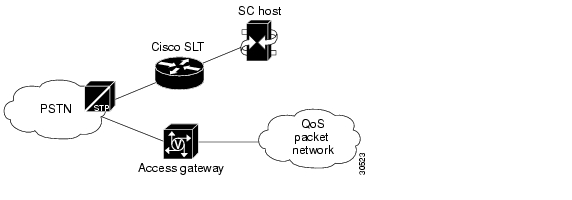
A simplex configuration is an SC zone that consists of a single SC host operating with one or more Cisco SLTs. The SC application is run on the SC host and the SS7 signaling links are terminated on the Cisco SLT. An IP control LAN is used to interconnect the host server with the Cisco SLTs. One or more access gateways are required for bearer channel termination. See Figure 2-1.

Quality of Service (QoS) packet network in Figure 2-1 refers to a packet network in which both bandwidth control and latency control are achieved for the particular application.


Note Simplex configurations provide no fault tolerance and are typically used for solution testing or validation or noncritical installations. If the host fails, calls are dropped, and service is discontinued.


Figure 2-1 Simplex Configuration Example

Continuous Service Configuration

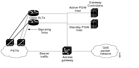
A continuous service configuration is an SC zone that consists of a pair of SC hosts running in an active (primary) and standby (secondary) mode, operating with one or more access gateways and one or more Cisco SLTs. An error-checking function runs continuously between the two SC hosts, monitoring the primary SC host. When the function detects an error condition on the primary SC host, responsibility for call processing is switched to the secondary SC host. The secondary SC host now becomes the active SC host; call preservation is maintained.

Figure 2-2 shows an example of a continuous service configuration with redundant signaling links terminating on a pair of Cisco SLTs with bearer traffic terminating on the access gateway.

Figure 2-2 Continuous Service Configuration Example

Signaling Network Connection Options

The Cisco SS7 Interconnect for Voice Gateways Solution performs functions to exchange telephone control messages between the following components that support the end user's signaling network connection:

Cisco Signaling Controller—Provides a signaling protocol conversion and network Q.931 call control to communicate with the access gateways. One signaling controller might provide signaling and call-processing services for multiple access gateways in geographically distributed locations, over redundant IP links used for ISDN signaling.

Cisco SLT—Handles the incoming and outgoing SS7 messages (MTP layer 1 and 2) from the A-links (access links) connected to Signal Transfer Points (STPs) or F-links connected to Service Switching Points (SSPs). Also, when used in Drop-and-Insert mode, the Cisco SLT grooms off the terminating signaling link from F-links (fully associated links) and then hairpins the bearer channels (ISUP) to the access gateway.

Cisco Access Gateway—Provides termination for PSTN trunks. An access gateway functions as a server to the SS7 bearer links. The access gateway has at least two IP network interfaces: one to carry IP packet data onto one or more of the Internet Service Provider's (ISP's) backbones and another to connect to the ISP's secure management, signaling, and Q.931 control network.

Your Cisco SS7 Interconnect for Voice Gateways Solution can be deployed in three ways, as described in "Simplex and Redundancy Options" section, with the following SS7 signaling network connections.


Note Type of connection would depend on your specific network requirements.


A-Link with Cisco SLT

F-Link with Cisco SLT

A-Link or F-Link with Cisco SLT (Drop-and-Insert)

A-Link with Cisco SLT

An A-link with Cisco SLT signaling connection is an access link from the PSTN Signal Transfer Point (STP) connected to the Cisco SLT of the SC node, through EIA/TIA-449, EIA/TIA-530, V.35, and T1/E1 interfaces. This option can be used with simplex and continuous service host configurations. Each interface supports a single signaling channel.

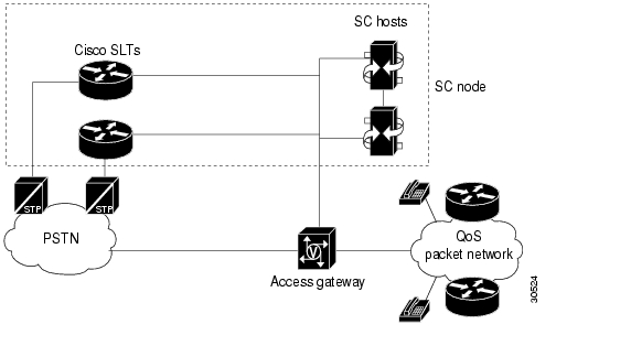
In the A-link SLT signaling connection, the Cisco SLT processes the two lowest-level SS7 signaling protocols, MTP1 and MTP2. The upper layer protocols are then forwarded to the SC host over the control signaling network. Each Cisco SLT supports two signaling network connections. Multiple Cisco SLTs can be used to support additional signaling channels or provide redundant signal paths between the signaling network and the control signaling network, as illustrated in Figure 2-3.

Figure 2-3 A-Link SLT Signaling Configuration

F-Link with Cisco SLT

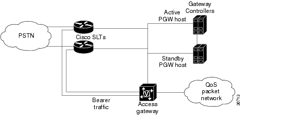
An F-link with Cisco SLT signaling connection is a fully associated link from the SS7 network to the Cisco SLT of the SC node. F-links connect the SC host directly to a Service Switching Point (SSP) or a Service Control Point (SCP) in the SS7 network; they do not make an intermediate connection through STPs.

The F-link SLT signaling configuration supports EIA/TIA-449, EIA/TIA-530, V.35, and T1/E1 interfaces that are installed in the Cisco SLT. The F-link SLT configuration can be used with simplex and continuous service SC host configurations. Each interface supports a single DS0 signaling channel.

A-Link or F-Link with Cisco SLT (Drop-and-Insert)

An A-link or F-link with Cisco SLT (Drop-and-Insert) signaling connection is similar, respectively, to an A-link or F-link SLT signaling connection. Fully associated links directly connect an SSP or SCP to the Cisco SLT. The difference is that the A-link and F-link Drop-and-Insert configurations support a single DS0 signaling channel per link and additional bearer traffic channels up to the capacity of the T1 or E1 link as shown in Figure 2-4.


Note The F-link Drop-and-Insert technique is also known as time-division multiplexing (TDM) cross-connect.


Figure 2-4 F-Link Drop-and-Insert Configuration

The F-link Drop-and-Insert signaling configuration supports T1 and E1 interfaces using signaling interface cards installed in the Cisco SLT. The Drop-and-Insert cards are special two-port cards designed for this application. Signal and bearer traffic enter one port together, then the Cisco SLT separates the bearer traffic and routes it out the second port.

The F-link Drop-and-Insert configuration can be used with simplex and continuous service host configurations. Each interface card supports a single DS0 signaling channel.

Control Signaling Network Options

Designing your network to handle control signaling is a complex and sophisticated task beyond the scope of this document. This section briefly describes what control signaling network options are available and some network engineering guidelines to consider.

Customer-Provided Equipment

Your control network consists of a number of hubs, switches, or routers configured together to support the number of ports in your point of presence (POP), the traffic characteristics of incoming calls, the geographic location of the Cisco SS7 Interconnect for Voice Gateways Solution components, and the level of redundancy that you require. Other factors to consider are:

Design of the network (topology and hardware components)

Security (physical, packet encryption, packet filtering)

Quality of service (delay, bandwidth, throughput, queuing techniques)

Traffic segregation (access lists and route filters)

Configuration of the components (RLM with the required SC host and access gateway/Cisco SLT redundancy, and timers)

Control traffic (signaling) should be segregated from the bearer data IP traffic (towards the internet/intranet) onto a different network. This optimizes control traffic latency and provides added security. Redundancy in your control network can be provided by duplicating your Cisco SS7 Interconnect for Voice Gateways Solution components. In the event that the control network fails or connectivity to it fails, the data network is used for signaling.

In the simplest case, your Cisco SS7 Interconnect for Voice Gateways Solution components are co-located and a pair of LAN switches serve as your control network. However, it is also possible that Cisco SLTs, and access gateways, are geographically separate from the SC hosts, requiring a control network with WAN links and separate routers to provide the WAN connection.

IP Connectivity with LAN

Figure 2-2 shows a sample continuous configuration with a mated Cisco SLT pair (for redundancy) on the control signaling network. Redundant signaling controllers support two or four Fast Ethernet connections each.

In this continuous configuration example, the control network functions are:

Checkpointing traffic (RUDP/UDP/IP)

Heartbeat (UDP; 50 bytes/second)

SNMP management of components (configurable to either network)

SC host/access gateway signaling and communications (Q.931+/Q921/UDP/IP-RLM)

SC host/Cisco SLT signaling and communications (MTP-3+ISUP/SM/RUPD/UDP/IP)

The QoS packet network functions are:

PSTN traffic over IP from and toward the Internet/Intranet

H.323 access gateway traffic

Access gateway/AAA (Radius/TACACS+server traffic)

IP Control Network Combinations

The following IP control network combinations are recommended:

One single subnet for all traffic.

Two redundant subnets: one dedicated to control traffic and the other for user data traffic and as alternative path for the control traffic.

Four redundant subnets: two redundant subnets for Cisco SLT/SC host traffic; two redundant subnets for access gateway/SC host traffic.


Note One of these subnet pairs must also run user data traffic.


Any combination of the above with VLANs configured in shared switches.


Note The subnet mentioned in your IP control network can be a dedicated hub or switch running at 10 or 100 Mbps (10 Mbps for SLTs) or a VLAN configured in a switch sharing backplane bandwidth with other VLANs.


Engineering Considerations

When engineering your network, you must consider the following issues:

There should be no packet loss, and the packets should not be received out of order between the signaling controller and the access gateways. This could impact the performance of the Cisco SS7 Interconnect for Voice Gateways Solution, and the call setup time might become unacceptable.

Do not enable load balancing in the control network. If you must use load balancing, you must also enable destination-based load balancing. In this case, use Cisco Express Forwarding (CEF) if available. If you do not use CEF, load balancing could cause out-of-sequence delivery when the cache ages out.

If you are using weighted fair queuing (WFQ) or any other type of queuing feature, make sure that all signaling packets from the access gateways to the signaling controller (and vice versa) show up in the same queues. Fancy Queuing is not recommended in the control network unless absolutely necessary.

If you are using dynamic routing protocols in the control network, out-of-sequence delivery could occur on a change of adjacency or topology. This should not be a normal occurrence in a stable network.

Cisco SS7 Interconnect for Voice Gateways Solution Components

The Cisco SS7 Interconnect for Voice Gateways Solution contains the following components:

SC Node Products

Access Gateways

LAN Switches (Optional)

Figure 2-5 displays the components of the Cisco SS7 Interconnect for Voice Gateways Solution.

See the "Overview" appendix for information about how the solution components operate within the SS7 hierarchy.

Figure 2-5 Cisco SS7 Interconnect for Voice Gateways Solution Components

SC Node Products

The SC node is the combination of hardware and software that provides the signaling controller function and transports the signaling traffic between the SC hosts and the SS7 signaling network. The SC node in the Cisco SS7 Interconnect for Voice Gateways Solution consists of one or more SC hosts, one or more Cisco SLTs, the signaling controller software, and ancillary equipment.

SC Host

An SC host is a Sun hardware platform running signaling controller software.

Table 2-1 lists supported SC hosts for the Cisco SC2200 product.

Table 2-1 Supported SC Hosts 

SC Host
Description

Sun Netra t 112x

The Sun Netra t 112x is a general-purpose Sun Ultra SPARC server. The Sun Netra t 112x is rack-mountable and is NEBS and ETSI compliant.

Sun Netra t 140x

The Sun Netra t 140x is a fault-tolerant, dual modular, redundant architecture. Additional lockstep operations give this host the ability to isolate and recover from hardware failure.


SC Host Features

The primary functions of the signaling controller is performing protocol conversion and call screening. The signaling controller is responsible for:

Interworking multiple-user protocols

Translating dialed digit information into data address information A-number and B-number analysis

Issuing control commands to the Transport layer to create, modify, or delete a call session now is

Generating comprehensive CDR on a call-by-call basis

Providing element management information and statistics

Providing comprehensive signaling debugging capabilities

Table 2-2 lists the features for the SC hosts.

Table 2-2 SC Host Features 

Feature
Support for ...

Call performance per signaling controller (simplex configuration with 20 minute call hold time)

80 call-per-second rate with 100,000 simultaneous calls on VSC Sun Netra t 140x platform, or,

45 call-per-second rate with 45,000 simultaneous calls on VSC Sun Netra t 1120 platform.

Call performance per signaling controller (continuous service configuration)

80 call-per-second rate with 100,000 simultaneous calls on VSC Sun Netra t 140x platform, or,

45 call-per-second rate with 45,000 simultaneous calls on VSC Sun Netra t 1120 platform.

Performance

Provisioning from MML or from an SNMP manager

Dynamic reconfiguration of point codes, linksets, trunk groups, and trunks

MML commands and responses

Application-level checking of call states and circuit states

Signaling protocols

SS7 with MTP2 configured on the Cisco SLT

Support for national protocols of many countries

Scaling of point codes

250+ DPCs and 6 OPCs

Network management interfaces

IP

Faults and alarms management

SNMP traps

Millisecond Timestamp

Millisecond time stamps on log records of diagnostic messages, set and clear alarm messages (sets and clears), alarm messages recorded by the Data Dumper, and alarm messages in the responses for the MML commands rtrv-alms and rtrv-alms:CONT.

Logging enhancements for Release 1.1

Improved system logging efficiency and your ability to diagnose problems.

The logging utility is enhanced in the following areas:

Enhanced log format: consistent, text-based message logs

Improved system efficiency: dynamic and non-service interrupting filtering capabilities for specific logging.

Improved user efficiency: inter-workability with other tools, such as grep utility, and improved log reliability.

Configuration management

Call Controller Manager (CCM), a TCL/tk graphic user interface (GUI) that uses Simple Network Management Protocol (SNMP) commands to provision the Cisco media gateway controller (MGC).


Note Call Controller Manager (CCM) is also referred to as Telephony Controller Manager (TCM) in earlier releases of this solution.


Man-Machine Language, a command-line interface to the MGC

Accounting

CDR (CSV format) support for international carrier requirements

Resource management

Keeps track of circuit IDs for assigning calls on access gateway ports

Manages adds, moves, and changes of access gateway resources

Performance measurements and statistics

Supports carrier requirements

Security

Structured system of passwords

Operating system

Sun Solaris 2.6.x

Dial Plan Provisioning Enhancements

Enable you to input a shortest digit sequence to the Cisco SC2200 number analysis table to define a range of digit strings for the same digit analysis treatment.

For example, for North America Numbering Plan (NANP) dial plans, the shortest digit sequence to identify the range of digit strings from 1 703-484-3000 through 1 703-484-3999 for the same digit analysis treatment would be 1 703-484-3 in the number analysis tables.

MML-control of call processing resources

Provide a MML command interface to allow or reject any new calls.

Route List Display

Display the symbolic name of a route list in the Telephony Controller Manager (TCM).

Configuration Upload/Download

Provide new configuration management capabilities using both the SNMP and MML interfaces to upload or download all the non-static configuration information.

MML Names in Log

Display component IDs in the terms of MML names in system logs.

Bearer Channel Level Tracing

Provide a call tracing capability using the MML interface to generate machine-readable traces to be used by Call Trace Viewer (CTV) applications.

Viewer Tools

Provide the following new viewing aids for system-generated data files:

Call Trace Viewer: A tool to display the specified call trace file.

CDR Viewer: A GUI-based tool to retrieve and display the specified CDR file or files.

Log Viewer: A GUI-based tool to retrieve and display the specified Cisco SC2200 log file or files.

Route Verification Viewer: A tool to display the summary of route translation by simulating the specified call through the active dialplan.

Memory Reduction

Provide a per-call, post-answer memory reduction mechanism to accommodate 100,000 simultaneous calls on Cisco SC2200 with the Netra ft 1800 SC host.


Caution The Memory Reduction mechanism may degrade the calls-per-second (CPS) rate. If CPS degrades by more than 5 percent, Cisco recommends that you disable this feature. Cisco also recommends that you never allow CPS to degrade by more than 20 percent.

Cisco SLT

The Cisco SLT handles the incoming and outgoing SS7 messages (MTP layer 1 and 2) that arrive from the PSTN Signal Transfer Points (STPs) or Service Switching Points (SSPs). When used in the proper configurations, the Cisco SLTs improve fault tolerance by providing for multiple communications paths between the SS7 signaling network and multiple SC hosts.

Cisco SLT Features

Table 2-3 lists Cisco SLT features.

Table 2-3 Cisco SLT Features  

Feature
Support for...

SS7 link termination on a high-availability platform

SS7 network access and interconnection requires a high degree of reliability in the signaling links and associated equipment. The Cisco SLT provides the reliability of a dedicated signaling link termination device and maximizes the availability of the SS7 signaling links.

Distributed SS7 MTP processing

Processor-intensive parts of the SS7 Message Transfer Part (levels1 and 2) are offloaded from the signaling controller to the Cisco SLT. This distributed MTP model allows the signaling controller to better utilize its resources to provide optimal call control.

Call control

Signaling backhaul provides a means for integrating the signaling link terminals into a virtual switch with the call control intelligence centralized in the signaling controller system.

Standard physical interfaces

Interconnection with SS7 network elements is supported using the most popular SS7 physical interface standards: T1, E1, T3, V.35, EIA/TIA-449, and EIA/TIA-530.

Drop-and-Insert

Cisco T1/E1 Multiflex Voice/WAN interface cards support Drop-and-Insert (also called TDM Cross-Connect), which allows individual T1/E1/T3 channels to be transparently passed, uncompressed, between T1/E1/T3 ports. This feature enables direct termination of SS7 F-links in T1/E1/T3 carriers, while the remaining bearer channels are hairpinned back to a gateway device for processing.


Cisco Media Gateway Controller Node Manager

CMNM provides the element-specific management features for the SC node. It blends the management framework features of the Cisco Element Management Framework (CEMF) with the individual interfaces and object structures of each managed element to produce an integrated management application. Table 2-4 lists the features of CMNM.

Table 2-4 Cisco Media Gateway Controller Node Manager Features  

Feature
Benefit

Performance monitoring

Collects performance information from the individual components of the SC node, allowing you to monitor the health and performance of the network.

Fault management

Provides fault management of the SC node, including the SC host, the Cisco SLT, and the optional LAN switch.

Security

Supports role-based access to management functions. The administrator defines user groups and assigns users to these groups.

Supports control of administrative state variables for SC node resources.

Troubleshooting

Provides the following for diagnostic and troubleshooting information:

CDR Viewer

Log Viewer

Trace Viewer

Translation Verification Viewer


Cisco Voice Services Provisioning Tool

The Cisco VSPT provides a graphical user interface (GUI) for the creation, modification, and execution of signaling connections, trunk groups, trunks, routes, and dial plans. It also allows users to import existing configurations for modification and then download the modified configurations to the same or different devices. To simplify operator tasks, such as trunk group provisioning, the Cisco VSPT employs a series of wizard-style templates combined with a user interface tailored for provisioning. Cisco VSPT automatically generates the Man Machine Language (MML) or command-line interface (CLI) scripts used to configure the network elements. Cisco VSPT may be used to bulk-create the initial network provisioning information for a newly installed node, creating iterative entries from a single operation action. It can also provide incremental provisioning of individual call parameters, simplifying the provisioning of large live networks.

Access Gateways

The access gateway terminates the PSTN trunks, also referred to as bearer channels, that carry the call traffic. The PSTN trunks are T1/E1/T3 PRI interfaces. In addition, the access gateway performs call control (including originating and terminating call processing/signaling).

Table 2-5 lists the features for the Cisco AS5x00.

Table 2-5 Cisco AS5x00 Features 

Feature
Support for...

Continuity testing

Automated diagnostic procedure

Redundant Link Manager

Virtual link management


LAN Switches (Optional)

The control signaling network for the Cisco SS7 Interconnect for Voice Gateways Solution often consists of a LAN switch and the cabling required to interconnect the solution components in an SC zone. This solution supports a LAN switch from the Cisco Catalyst switch family. This switch can extend VLANs across platforms through backbone Fast Ethernet, Gigabit, or ATM connections, when necessary.


Note The Catalyst LAN switch is not provided with the Cisco SC2200 product.


hometocprevnextglossaryfeedbacksearchhelp

Posted: Thu Oct 14 10:11:00 PDT 2004
All contents are Copyright © 1992--2004 Cisco Systems, Inc. All rights reserved.
Important Notices and Privacy Statement.