|
|

Table Of Contents
Configuring Media Gateways for the SS7 Interconnect for Voice Gateways Solution
Determining Software and Hardware Requirements
Installing the Cisco AS5300 Universal Access Server
Installing the Cisco AS5350 Universal Gateway
Installing the Cisco AS5400 Universal Gateway
Installing the Cisco AS5800 Universal Access Server
Installing the Cisco AS5850 Universal Gateway
Configuring the Cisco AS5300 and Cisco AS5850 for B-Channel Negotiation
Configuring Redundant Link Manager
Configuring Number Translation
Configuring Dial Peer Call Legs Using Digit Translation Rules
Sample Output for the Cisco SS7 Interconnect for Voice Gateways Solution
Configuring Media Gateways for the SS7 Interconnect for Voice Gateways Solution
This chapter describes how to configure the access servers used by the Cisco SS7 Interconnect for Voice Gateways Solution. It includes the following sections:
•
Determining Software and Hardware Requirements
•
Determining Software and Hardware Requirements
Software and hardware requirements vary depending on the version of the Cisco SS7 Interconnect for Voice Gateways Solution installed in your network. To view the latest requirements for your solution, see the following online documentation:
•
http://www.cisco.com/univercd/cc/td/doc/product/access/sc/rel7/soln/voip13/voip_rn.htmInstalling Media Gateways
This document assumes that all required hardware, voice feature cards, and network modules have been installed, and that each access server or router has been connected to a working IP network. If necessary, refer to the following sections:
•
•
•
•
•
Installing the Cisco AS5300 Universal Access Server
For instructions on installing a Cisco AS5300 and connecting it to a network, see the following documents:
•
•
•
•
The entire documentation set for the Cisco AS5300 universal access server is available at the following location:
http://www.cisco.com/univercd/cc/td/doc/product/access/acs_serv/5300/index.htm
Installing the Cisco AS5350 Universal Gateway
For instructions on installing a Cisco AS5350 and connecting it to a network, see the following documents:
•
•
•
The entire documentation set for the Cisco AS5350 universal gateway is available at the following location:
http://www.cisco.com/univercd/cc/td/doc/product/access/acs_serv/as5350/index.htm
Installing the Cisco AS5400 Universal Gateway
For instructions on installing a Cisco AS5400 and connecting it to a network, see the following documents:
•
•
•
•
The entire documentation set for the Cisco AS5400 universal gateway is available at the following location:
http://www.cisco.com/univercd/cc/td/doc/product/access/acs_serv/as5400/index.htm
Installing the Cisco AS5800 Universal Access Server
For instructions on installing a Cisco AS5800 and connecting it to a network, see the following documents:
•
•
•
•
The entire documentation set for the Cisco AS5800 universal access server is available at the following location:
http://www.cisco.com/univercd/cc/td/doc/product/access/acs_serv/as5800/index.htm
Installing the Cisco AS5850 Universal Gateway
For instructions on installing a Cisco AS5850 and connecting it to a network, see the following documents:
•
•
•
•
Note
http://www.cisco.com/univercd/cc/td/doc/product/software/ios122/122newft/122limit/122x/122xb/122xb_2/handred.htm
The entire documentation set for the Cisco AS5850 universal gateway is available at the following location:
http://www.cisco.com/univercd/cc/td/doc/product/access/acs_serv/as5850/index.htm
Configuring Media Gateways
The process for configuring voice gateways includes the following major steps:
•
•
•
•
•
•
Setting the ISDN Switch Type
To communicate with the Cisco SC2200, you must set the appropriate ISDN switch type on the media gateway. To set the ISDN switch type, perform the following steps:
Step 1
Router# configure terminalRouter(config)#Step 2
Router# isdn switch-type primary-niFor more information about setting ISDN switch types, refer to National ISDN Switch Types for Basic Rate and Primary Rate Interfaces at the following location;
http://www.cisco.com/univercd/cc/td/doc/product/software/ios113ed/113t/113t_3/natisdn.htmConfiguring the Cisco AS5300 and Cisco AS5850 for B-Channel Negotiation
To improve call success rates, the Cisco AS5300 and Cisco AS5850 must be configured to negotiate ISDN B-channels with the Cisco Media Gateway Controller (MGC). This negotiation enables the MGC to setup the call on a different channel if the channel requested by the media gateway is unavailable.
To enable ISDN B-channel negotiation, perform the following steps:
Step 1
Router# configure terminalRouter(config)#Step 2
Router(config)# interface {s0:23 | s0:15}
Note
Step 3
Router(config-if)# isdn negotiate-bRouter(config-if)# isdn negotiate-bchanConfiguring Redundant Link Manager
Redundant Link Manager (RLM) provides virtual link management over multiple IP networks so that the Q.931 signaling protocol and other proprietary protocols can be transported on top of redundant links between the Cisco SC2200 and the media gateways. RLM opens, maintains, and closes multiple links, manages buffers of queued signaling messages, and monitors for both link failover and failover of the Cisco SC2200. Additionally, RLM allows these multiple, redundant paths to be treated as one path by upper layers.
Note
Q.921 is used to encapsulate the Q.931 messages, which guarantees the in-sequence transmission of Extended Q.931 messages and provides for retransmission when necessary. UDP provides for the connectionless transfer of signaling messages across the subnetworks (LAN or WAN) that connect the media gateways to the Cisco SC2200.
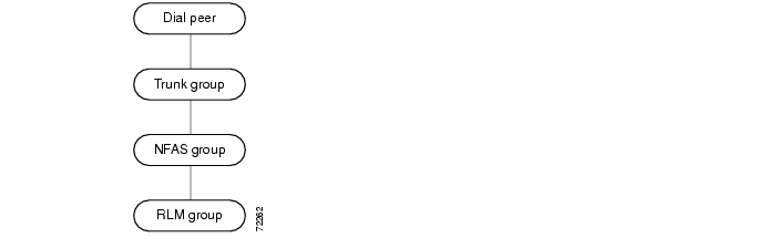
Because RLM handles all signaling between the Cisco SC2200 and the media gateway, D channels can be used to carry bearer traffic. This is accomplished through the use of Non-Facility Associated Signaling (NFAS). NFAS allows a single D channel to control multiple PRI interfaces. That single D channel is then mapped to the RLM group.
Figure 2-1 shows the mapping that occurs between a VoIP or POTS dial peer and the RLM group.
Figure 2-1 Call Flow from Dial Peer to RLM Group
Note
http://www.cisco.com/univercd/cc/td/doc/product/software/ios120/120newft/120t/120t3/rlm_123.
h tm
Note
Assigning RLM Groups
Step 1
Caution
http://www.cisco.com/univercd/cc/td/doc/product/access/sc/rel7/soln/wv_rel1/wvpg/index.htm
rlm group 0protocol rlm port 3002 <---arbitraryserver columbialink address 10.40.0.10 source FastEthernet0/0 weight 2link address 10.41.0.10 source FastEthernet0/1 weight 1server fairfieldlink address 10.40.0.11 source FastEthernet0/0 weight 2link address 10.41.0.11 source FastEthernet0/1 weight 1Assigning Multiple RLM Groups
Voice gateways in this solution can support up to eight RLM groups per gateway. This capability enables you to spread trunks over multiple gateways. In order for the Cisco SC2200 to distinguish among the different RLM groups on each gateway, you must assign a unique UDP port number to each RLM group on a gateway.
Note
Step 1
interface Serial1/0/0:23ip unnumbered Loopback0dialer pool-member 1isdn switch-type primary-niisdn incoming-voice modemisdn calling-number 333444333isdn rlm-group 1no isdn send-status-enquiryisdn negotiate-bchanisdn bchan-number-order ascendinginterface Serial1/0/3:23ip unnumbered Loopback0dialer pool-member 1isdn switch-type primary-niisdn incoming-voice modemisdn calling-number 333444333isdn rlm-group 2no isdn send-status-enquiryisdn negotiate-bchanisdn bchan-number-order ascendingStep 2
rlm group 1server fifilink address 10.4.8.10 source Loopback1 weight 90
Note
Step 3
rlm group 2protocol rlm port 3001server fifilink address 10.4.8.10 source Loopback2 weight 90Be sure to include the corresponding UDP ports when you configure RLM groups on the Cisco SC2200.
Configuring RLM on the Cisco AS5300, Cisco AS5350, Cisco AS5400, Cisco AS5800, and
Classic-Split Mode Cisco AS5850To configure RLM on media gateways other than a Cisco AS5850 in handover-split mode, perform the following steps:
Step 1
Router> enablePassword: passwordRouter#Step 2
Router# configure terminalRouter(config)#Step 3
Router(config)# interface FastEthernet0Step 4
Router(config-if)# rlm group 0Router(config-rlm-group)#Step 5
Router(config-rlm-group)# server mgc1Step 6
Router(config-rlm-group-sc)# link address 10.1.4.1 source FastEthernet0 weight1Router(config-rlm-group-sc)# link address 10.1.4.2 source FastEthernet0 weight2
Note
Step 7
Router(config-rlm-group-sc)# server mgc2Router(config-rlm-group-sc)# link address 10.1.5.1 source FastEthernet0 weight1Router(config-rlm-group-sc)# link address 10.1.5.2 source FastEthernet0 weight2Step 8
Router(config-rlm-group-sc)# router eigrp 100Router(config-router)#Step 9
Router(config-controller)# pri-group timeslots 1-24 nfas_d primary nfas_int 0 nfas_group 0Router(config-controller)# pri-group timeslots 1-24 nfas_d none nfas_int 1 nfas_group 0Router(config-controller)# pri-group timeslots 1-24 nfas_d none nfas_int 2 nfas_group 0Router(config-controller)# pri-group timeslots 1-24 nfas_d none nfas_int 27 nfas_group 0
Note
http://www.cisco.com/univercd/cc/td/doc/product/software/ios113ed/113t/113t_3/nfas.htm
Configuring RLM on a Handover-Split Mode Cisco AS5850
A Cisco AS5850 configured for handover-split mode provides greater redundancy and system availability by enabling each RSC to automatically take control of call processing if the other RSC fails. In normal operation, the RSC in slot 6 controls slots 0 through 5, and the RSC in slot 7 controls slots 8 through 13. When an RSC failure occurs in handover-split mode, the remaining RSC takes over control of all slots, cards, and call processing. The failed RSC will remain in a standby state until the active RSC is instructed to relinquish control of the slots usually controlled by the standby RSC.
Because of the different architecture used by the Cisco AS5850, RLM requires a different configuration to take advantage of handover-split mode. For each RSC, you must configure two RLM groups: an active RLM group to handle calls on the slots controlled by that RSC, and a standby RLM group to handle calls on the other slots if the other RSC fails. Table 2-1 shows the status of these four RLM groups during normal operation and when an RSC goes out of service.
Handover-Split Mode Limitations
Cisco AS5850s configured for handover-split mode operate under the following limitations:
•
•
For detailed information on classic-split and handover-split modes, refer to the following online documentation:
http://www.cisco.com/univercd/cc/td/doc/product/software/ios122/122newft/122limit/122x/122xb/122xb_2/handred.htmConfiguring RLM Groups Associated with RSC 0
To configure RLM groups for RSC 0 on a handover-split mode Cisco AS5850, perform the following steps:
Step 1
Router> enablePassword: passwordRouter#Step 2
Router# configure terminalRouter(config)#Step 3
Router(config)# interface GigabitEthernet 6/0Step 4
Router(config-if)# rlm group 0Router(config-rlm-group)#Step 5
Router(config-rlm-group)# server mgc1Router(config-rlm-group-sc)# link address 10.1.4.1 source GigabitEthernet0 weight1 Router(config-rlm-group-sc)# server mgc2Router(config-rlm-group-sc)# link address 10.1.5.1 source GigabitEthernet0 weight2
Note
Step 6
Step 7
controller T1 2/0:1framing esfpri-group timeslots 1-24 nfas_d primary nfas_int 0 nfas_group 0!controller T1 2/0:2framing esfpri-group timeslots 1-24 nfas_d none nfas_int 1 nfas_group 0!controller T1 2/0:3framing esfpri-group timeslots 1-24 nfas_d none nfas_int 2 nfas_group 0!controller T1 2/0:28framing esfpri-group timeslots 1-24 nfas_d none nfas_int 27 nfas_group 0!controller T1 10/0:1framing esfpri-group timeslots 1-24 nfas_d primary nfas_int 0 nfas_group 1!controller T1 10/0:2framing esfpri-group timeslots 1-24 nfas_d none nfas_int 1 nfas_group 1!controller T1 10/0:3framing esfpri-group timeslots 1-24 nfas_d none nfas_int 2 nfas_group 1!controller T1 10/0:28framing esfpri-group timeslots 1-24 nfas_d none nfas_int 27 nfas_group 1Step 8
interface Serial2/0:1:23isdn switch-type primary-niisdn incoming-voice modemisdn rlm-group 0interface Serial10/0:1:23isdn switch-type primary-niisdn incoming-voice modemisdn rlm-group 1Step 9
rlm group 1protocol rlm 3002
Note
Step 10
rlm group 1shutdownprotocol rlm port 3002server mgc1link address 10.1.4.1 source GigabitEthernet6/0 weight 1server mgc2link address 10.1.5.1 source GigabitEthernet6/0 weight 2Configuring RLM Groups Associated with RSC 1
To configure RLM groups for RSC 1 on a handover-split mode Cisco AS5850, perform the following steps:
Step 1
Router> enablePassword: passwordRouter#Step 2
Router# configure terminalRouter(config)#Step 3
Router(config)# interface GigabitEthernet 7/0Step 4
Router(config-if)# rlm group 2Router(config-rlm-group)#Step 5
Router(config-rlm-group)# server mgc1Router(config-rlm-group-sc)# link address 10.1.4.1 source GigabitEthernet0 weight1 Router(config-rlm-group-sc)# server mgc2Router(config-rlm-group-sc)# link address 10.1.5.1 source GigabitEthernet0 weight2Step 6
Step 7
controller T1 2/0:1framing esfpri-group timeslots 1-24 nfas_d primary nfas_int 0 nfas_group 3!controller T1 2/0:2framing esfpri-group timeslots 1-24 nfas_d none nfas_int 1 nfas_group 3!controller T1 2/0:3framing esfpri-group timeslots 1-24 nfas_d none nfas_int 2 nfas_group 3!controller T1 2/0:28framing esfpri-group timeslots 1-24 nfas_d none nfas_int 27 nfas_group 3!controller T1 10/0:1framing esfpri-group timeslots 1-24 nfas_d primary nfas_int 0 nfas_group 2!controller T1 10/0:2framing esfpri-group timeslots 1-24 nfas_d none nfas_int 1 nfas_group 2!controller T1 10/0:3framing esfpri-group timeslots 1-24 nfas_d none nfas_int 2 nfas_group 2!controller T1 10/0:28framing esfpri-group timeslots 1-24 nfas_d none nfas_int 27 nfas_group 2Step 8
interface Serial2/0:1:23isdn switch-type primary-niisdn incoming-voice modemisdn rlm-group 3interface Serial10/0:1:23isdn switch-type primary-niisdn incoming-voice modemisdn rlm-group 2Step 9
rlm group 2protocol rlm port 3002no shutdownStep 10
rlm group 3protocol rlm 3000shutdown
Verifying RLM Configuration
To verify RLM configuration, perform the following steps:
Note
Step 1
Router# show rlm group 0 statusRLM Group 0 StatusUser/Port: RLM_MGR/3000 ISDN3001Link State: Up Last Link Status Reported: UpNext tx TID: 1 Last rx TID: 0Server Link Group[mgc1]:link [10.1.1.1(Ethernet0), 10.1.4.1] = socket[active]link [10.1.1.2(FastEthernet0), 10.1.4.2] = socket[standby]Server Link Group[mgc2]:link [10.1.1.1(Ethernet0), 10.1.5.1] = socket[opening]link [10.1.1.2(FastEthernet0), 10.1.5.2] = socket[opening]The link state must be up, and no errors should be reported.
Step 2
Router# show isdn statusGlobal ISDN Switchtype = primary-niISDN Serial1:23 interfacedsl 0, interface ISDN Switchtype = primary-ni :Primary D channel of nfas group 0Layer 1 Status:ACTIVELayer 2 Status:TEI = 0, Ces = 1, SAPI = 0, State = MULTIPLE_FRAME_ESTABLISHEDLayer 3 Status:0 Active Layer 3 Call(s)Activated dsl 0 CCBs = 0ISDN Serial2:23 interfacedsl 1, interface ISDN Switchtype = primary-ni :Group member of nfas group 0Layer 1 & 2 Status Not ApplicableLayer 3 Status:0 Active Layer 3 Call(s)Activated dsl 1 CCBs = 0Total Allocated ISDN CCBs = 0For Serial 0:23 (the first half of the message):
•
•
•
The second half of the message displays information for Serial 1:23.
Tip
A Layer 2 error indicates that the Cisco MGW cannot communicate with the telco; there is a problem at the data link layer. There may be a problem with your telco, or the framing and line code types you entered may not match that of your telco.
Completing VoIP Configuration
This section lists the steps to configure the voice gateways in your solution to use Voice over IP (VoIP). Perform the following steps to complete this configuration:
Step 1
http://www.cisco.com/univercd/cc/td/doc/product/software/ios121/121cgcr/ip_c/index.htmStep 2
•
http://www.cisco.com/univercd/cc/td/doc/product/software/ios120/120newft/120t/120t3/voip5300/voip53_1.htm4934vcip.htm•
http://www.cisco.com/univercd/cc/td/doc/product/access/acs_serv/as5350/53swcg/index.htmStep 3
•
•
•
Step 4
•
•
•
•
•
•
Note
http://www.cisco.com/univercd/cc/td/doc/product/software/ios121/121newft/121limit/121x/121xm/121xm_5/ftdpeer.htm
Cisco SS7 Interconnect for Voice Gateways Solution also offers VFC management features that enable you to easily upgrade and manage the system software stored in VFC Flash memory. Depending on your configuration, you might need to perform the following tasks to manage VCWare or DSPWare:
•
•
•
•
•
•
•
•
•
Configuring Number Translation
Number translation is used in dial-peer configuration mode to match on a number type for a dial peer call leg.
To configure number translation using the numbering-type command in dial-peer configuration mode, enter the following commands in global configuration mode:
Configuring the Digit Strip
When a called number is received and matched to a POTS dial peer, the matched digits are stripped and the remaining digits are forwarded to the voice interface. The Cisco SS7 Interconnect for Voice Gateways Solution implements a new command called the digit strip option to make this default behavior an option. The digit strip option is enabled by default.
To disable digit strip for a dial peer, enter the following commands in global configuration mode:
Configuring Dial Peer Call Legs Using Digit Translation Rules
A dial peer defines the characteristics associated with a call leg. Dial peers are used to apply attributes to call legs and to identify call origin and destination. Attributes applied to a call leg include QoS, codec, VAD, and fax rate. A call leg is a discrete segment of a call connection that lies between two points in the connection. All of the call legs for a particular connection have the same connection ID.
There are two different kinds of dial peers:
•
•
A POTS dial peer points to a voice-port on the router, while the destination of a VoIP dial peer points to the destination IP address of the voice-router that terminates the call.
Complete the following procedures to configure call legs using the translation-rule command:
Tip
Step 1
Note
Step 2
Step 3
Step 4
Step 5
Sample Configuration and Output for Voice-over-IP
Following is a sample output from a Cisco AS5300 set up for bearer channels for VoIP:
Step 1
hostname XXXXXX!no logging bufferedno logging consoleaaa new-modelStep 2
!username voice passwordusername lab password!!resource-pool disable!!!ip subnet-zerono ip domain-lookupip host carteret 10.15.12.134 10.15.12.150ip host YauPon 10.15.12.135 10.15.12.151!mgcp package-capability trunk-packagemgcp default-package trunk-packageStep 3
isdn voice-call-failure 0cns event-service servermta receive maximum-recipients 0!dial-control-mib max-size 1200!Step 4
framing esflinecode b8zscablelength short 133pri-group timeslots 1-24!Step 5
framing esflinecode b8zscablelength short 133pri-group timeslots 1-24!Step 6
framing esfclock source line secondary 1linecode b8zscablelength short 133Step 7
This command links the PRI bearer channels on the media gateway to the RLM group for D-channel communication to the signaling controller over IP. The nfas_group number represents one or more PRIs that are controlled by the same D-channel. The int number should be configured to match the T-1 controller number.
Some tips to remember when configuring are as follows:
•
•
•
•
Step 8
framing esfclock source line primarylinecode b8zscablelength short 133Step 9
The voice ports will be automatically configured as shown below. The voice-port is created as a result of pri group nfas command. Voice ports 2:D and 3:D will be used in nfas-group 0.
!!voice-port 0:D!voice-port 1:D!voice-port 2:D!voice-port 3:DThe dial peers shown below are classic examples of Cisco H.323 provisioning to reach call destination.
Step 10
destination-pattern 471.......direct-inward-dialport 2:Dprefix 471!Step 11
destination-pattern 4514101...direct-inward-dialport 0:Dprefix 4514101!Step 12
destination-pattern 4514102...direct-inward-dialport 1:Dprefix 4514102!Step 13
destination-pattern 4101...direct-inward-dialport 0:Dprefix 4101!Step 14
destination-pattern 4102...direct-inward-dialport 1:Dprefix 4102!Step 15
destination-pattern 271.......session target ipv4:172.18.193.110tech-prefix 271#!num-exp 451#.......... ..........num-exp 451#....... .......num-exp 471#.......... ..........!gateway!Step 16
ip address 10.15.14.233 255.255.255.252no ip directed-broadcasth323-gateway voip interfaceh323-gateway voip id z3-gk1 ipaddr 10.15.14.197 1719h323-gateway voip h323-id z3-5300-1h323-gateway voip tech-prefix 451#h323-gateway voip tech-prefix 471#!Step 17
ip address 10.15.12.2 255.255.255.240no ip directed-broadcast!Step 18
Step 19
This command is created as a result of the RLM global configuration command that resides at the bottom of the configuration.
Step 20
This command allows the SC to communicate with the Cisco Media Gateway for call signaling and bearer channel control over UDP ports 3000 for Q.921 keepalives and 3001 for Q931 call setup.
server name xlink address 10.15.12.134 source Ethernet0 weight 5link address 10.15.12.150 source FastEthernet0 weight 2server name ylink address 10.15.12.135 source Ethernet0 weight 5link address 10.15.12.151 source FastEthernet0 weight 2radius-server host 10.15.12.6 auth-port 1645 acct-port 1646radius-server key tvtestRadius configuration is used for authentication and accounting records.
Step 21
Network Time Protocol (NTP) is recommended to synchronize all the components of the solution to the same time reference. This can be achieved with the router or another NTP device such as the master source.
Verifying the Configuration
To verify the configuration perform the following steps:
Step 1
ISDN NFAS GROUP 0 ENTRIES:The primary D is Serial2:23.The NFAS member is Serial3:23.The example shown above indicates the primary D-channel interface and its associated members in the group. There are two total NFAS members.There are 48 total available B channels.
The primary D-channel is DSL 2 in the IN SERVICE state.
There is currently no backup D-channel configured.
The current active layer 2 DSL is 2.
Step 2
ISDN Serial2:23 interface rlm-group = 0dsl 2, interface ISDN Switchtype = primary-ni : Primary D channel of nfas group 0Layer 1 Status:ACTIVELayer 2 Status:TEI = 0, Ces = 1, SAPI = 0, State = MULTIPLE_FRAME_ESTABLISHEDI_Queue_Len 0, UI_Queue_Len 0Layer 3 Status:0 Active Layer 3 Call(s)Activated dsl 2 CCBs = 0The Free Channel Mask: 0x80FFFFFFISDN Serial3:23 interfacedsl 3, interface ISDN Switchtype = primary-ni : Group member of nfas group 0Layer 1 Status:ACTIVELayer 2 Status: Not ApplicableLayer 3 Status:0 Active Layer 3 Call(s)Activated dsl 3 CCBs = 0Step 3
The presence of two signaling controllers shown below, indicates redundancy in the case of failover. This step is optional.
RLM Group 0 StatusUser/Port: RLM_MGR/3000 ISDN/3001RLM Version : 2Link State: Up Last Link Status Reported: UpNext tx TID: 1 Last rx TID: 0Server Link Group[carteret]: Last Reported Priority: HIGHlink [10.15.12.2(Ethernet0), 10.15.12.134] = socket[standby]link [10.15.12.34(FastEthernet0), 10.15.12.150] = socket[standby]Server Link Group[yaupon]: Last Reported Priority: HIGHlink [10.15.12.2(Ethernet0), 10.15.12.135] = socket[active]link [10.15.12.34(FastEthernet0), 10.15.12.151] = socket[standby]This is the interface that call signaling will traverse.
RLM Group 0 Timer Valuesopen_wait = 3s force-down = 30srecovery = 12s switch-link = 5sminimum-up = 60s retransmit = 1skeepalive = 1sRLM Group 0 StatisticsLink_up:last time occurred at Nov 18 10:57:43.992, total transition=59avg=06:36:36.298, max=2d22h, min=00:00:00.000, latest=00:00:04.844Link_down:last time occurred at Nov 18 10:57:10.992, total transition=28avg=00:56:54.621, max=1d00h, min=00:00:00.000, latest=00:00:33.000Link_recovered:last time occurred at Nov 18 10:56:58.992, success=25(49%), failure=26avg=0.038s, max=0.224s, min=0.000s, latest=0.000sLink_switched:last time occurred at Nov 11 12:25:52.324, success=6(100%), failure=0avg=0.000s, max=0.000s, min=0.000s, latest=0.000sServer_changed:last time occurred at Nov 18 10:56:54.148 for totally 29 timesServer Link Group[carteret]:Open the link [10.15.12.2(Ethernet0), 10.15.12.134]:last time occurred at Nov 18 10:57:40.992, success=33(6%), failure=509-0avg=43.634s, max=177.004s, min=0.000s, latest=0.000sEcho over link [10.15.12.2(Ethernet0), 10.15.12.134]:last time occurred at Nov 18 11:12:40.979, success=1355251(97%), failure=33527-0avg=0.000s, max=0.964s, min=0.000s, latest=0.000sOpen the link [10.15.12.34(FastEthernet0), 10.15.12.150]:last time occurred at Nov 18 10:57:40.992, success=33(6%), failure=509-0avg=43.549s, max=177.004s, min=0.000s, latest=0.000sEcho over link [10.15.12.34(FastEthernet0), 10.15.12.150]:last time occurred at Nov 18 11:12:40.979, success=1378593(97%), failure=32887-0avg=0.000s, max=0.960s, min=0.000s, latest=0.000sServer Link Group[yaupon]:Open the link [10.15.12.2(Ethernet0), 10.15.12.135]:last time occurred at Nov 18 10:57:40.992, success=35(1%), failure=2247-0avg=61.347s, max=177.000s, min=0.000s, latest=0.004sEcho over link [10.15.12.2(Ethernet0), 10.15.12.135]:last time occurred at Nov 18 11:12:41.983, success=998740(87%), failure=139142-0avg=0.000s, max=2.688s, min=0.000s, latest=0.004sOpen the link [10.15.12.34(FastEthernet0), 10.15.12.151]:last time occurred at Nov 18 10:57:40.992, success=35(1%), failure=2247-0avg=61.270s, max=177.000s, min=0.000s, latest=0.032sEcho over link [10.15.12.34(FastEthernet0), 10.15.12.151]:last time occurred at Nov 18 11:12:42.019, success=1059514(88%), failure=138872-0 avg=0.000s, max=2.688s, min=0.000s, latest=0.016s
Sample Output for the Cisco SS7 Interconnect for Voice Gateways Solution
The following sections contain sample output for a voice gateway that has been configured for the Cisco SS7 Interconnect for Voice Gateways Solution.
!version 12.1no service padservice timestamps debug datetime msec localtimeservice timestamps log uptimeno service password-encryptionservice internal!hostname!no logging consoleenable password!username allspe 1/0 2/9firmware location system:/ucode/mica_port_firmware!!resource-pool disable!!!!modem recovery action noneip subnet-zerono ip domain-lookupip host holden 10.15.0.1!isdn switch-type primary-nimta receive maximum-recipients 0!!controller E1 0framing NO-CRC4clock source line primarypri-group timeslots 1-31 nfas_d primary nfas_int 0 nfas_group 0!controller E1 1framing NO-CRC4pri-group timeslots 1-31 nfas_d none nfas_int 1 nfas_group 0!controller E1 2shutdownframing NO-CRC4clock source line secondary 1pri-group timeslots 1-31 nfas_d none nfas_int 2 nfas_group 0!controller E1 3shutdownframing NO-CRC4pri-group timeslots 1-31 nfas_d none nfas_int 3 nfas_group 0!!!!interface Ethernet0ip address 209.165.200.224 255.255.255.224no ip directed-broadcastno ip route-cacheno ip mroute-cache!interface Serial0:15no ip addressip helper-address 209.165.200.224no ip directed-broadcastno ip route-cacheisdn switch-type primary-niisdn incoming-voice modemisdn rlm-group 1no fair-queueno cdp enable!interface FastEthernet0ip address 209.165.200.224 255.255.255.224no ip directed-broadcastno ip route-cacheno ip mroute-cacheduplex full!interface Group-Async1description "Async Incoming Call"no ip addressno ip directed-broadcastno ip route-cacheno ip mroute-cacheasync dynamic addressasync mode interactiveno snmp trap link-statusno peer default ip addressno fair-queuegroup-range 1 120!interface Dialer0no ip addressno ip directed-broadcastno cdp enable!router ripredistribute connectednetwork 10.0.0.0!no ip classlessno ip http server!logging 10.15.0.130!dialer dnis group dnis1number 9157181dialer-list 1 protocol ip permitdialer-list 1 protocol ipx permitsnmp-server engineID local 00000009020000D00604FB36snmp-server community public ROsnmp-server community RWsnmp-server trap-source FastEthernet0snmp-server system-shutdownsnmp-server enable traps snmpsnmp-server enable traps isdn call-informationsnmp-server enable traps isdn layer2snmp-server enable traps hsrpsnmp-server enable traps configsnmp-server enable traps entitysnmp-server enable traps envmonsnmp-server enable traps bgpsnmp-server enable traps rsvpsnmp-server enable traps frame-relaysnmp-server enable traps rtrsnmp-server enable traps syslogsnmp-server enable traps dlswsnmp-server enable traps dialsnmp-server enable traps dsp card-statussnmp-server enable traps voice poor-qovsnmp-server host 10.15.0.130 public!rlm version 2!rlm group 1server xxxxlink hostname xxx source Ethernet0 weight 1!line con 0exec-timeout 0 0transport input noneline 1 120logging synchronous level 7modem InOuttransport preferred lat pad telnet rlogin udptn v120transport input alltransport output pad telnet rlogin udptn v120line aux 0line vty 0 4exec-timeout 0 0passwordlogin!ntp clock-period 17179771ntp update-calendarntp server 10.15.0.1 source FastEthernet0end
![]()
![]()
![]()
![]()
![]()
![]()
![]()
![]()
Posted: Thu Oct 14 10:34:52 PDT 2004
All contents are Copyright © 1992--2004 Cisco Systems, Inc. All rights reserved.
Important Notices and Privacy Statement.