|
|

An important component of efficient network management is the ability to receive performance information on a large network of many devices to provide an overall view of the your network's functioning. You can then pro-actively manage your network elements by analyzing the performance data.
CMNM lets you monitor the performance statistics gathered from network elements managed by CEMF. CMNM collects performance information from the Cisco MGC node, allowing you to monitor the health and performance of the network. You can display the performance information. You can also view performance data associated with a given object and graph that data over time. CMNM collects performance information from all of the components of the Cisco MGC node. You can configure the objects being polled and the frequency of the polling.
Cisco MGC allows you to specify how long performance data should be kept in the database. You can also specify rollup-rules and other actions that should be taken on performance data after a set length of time.
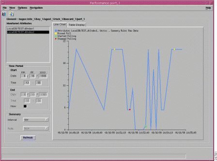
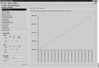
The Performance Manager is opened from the Network Maps, Event Browser, or Object Manager by selecting Performance Manager from the pop-up menu available on a selected object. A screen similar to Figure 7-1 is displayed.
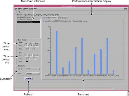
A selected object or group of objects has a number of different attributes. You can choose to monitor an area of the network, for example, the performance statistics of a particular attribute. This information could then be used to evaluate the performance of specific equipment and assess the requirements for upgrades or software downloads.
Performance statistics also provide a summary view of the performance of network elements. These statistics help you determine the degree to which the network is meeting assigned service levels. You are able to drive down to the chassis level from the network level in a simple manner if you want to view individual chassis statistics.
CMNM Performance Manager can present data in two ways:
Performance data has the potential to overwhelm. For example, you may wish to view the Errored Packets for a device over a six-month interval. If the data was displayed in a table or graph at the rate at which it was sampled, this could be tens of thousands of values. In these circumstances, it is preferable to view summaries of the data. For example, if data was originally received at intervals of 5 minutes, the ability to view it summarized in hourly, daily, or weekly intervals would be an excellent way of managing the network. History storage criteria can be used to specify these summary intervals and the rules which are used to generate the summaries for the history storage criteria's objects and attributes.
Hourly summaries are generated on the hour, daily summaries are generated at midnight, and weekly summaries are generated at midnight on Sundays (that is, the end of Sundays). For example, if polling starts at 9:30 and hourly summaries are to be generated, the first full hour's worth of data is between 10:00 and 11:00. So at 11:00, the first hourly summary is generated, and given a timestamp of 10:00. The same pattern is followed for all summaries (daily, weekly, or user-defined). This pattern standardizes summary intervals so that all attributes' summaries have the same timestamps.
 |
Note Data generated between 9:30 and 10:00 is ignored in the above example, because an hourly summary for 9:00 to 10:00 would be misleading as it would have been generated using only half the usual number of values. |
In some cases, an object may fail to be polled; for example, if communication to the object is lost. This is referred to as a missed poll, and all missed polls are indicated on Performance Manager graphs and charts.
Performance Manager graphs and charts also indicate when an attribute started and stopped being polled due to history storage criteria being added, edited, or removed. You are therefore able to see when polling on an attribute started, the attribute's values while it was being polled (and any missed polls), and finally when the attribute stopped being polled.
A Performance Manager can be opened for each network element you wish to monitor. To view up-to-date information on the Performance Manager, click Refresh and the selected data is displayed.
Depending on the type of device, performance data is collected in different ways.
Collection of performance data from the active Cisco MGC host is different from the other Cisco MGC node devices. CMNM does not use SNMP to collect this data. Rather, the Cisco MGC host software writes out performance data files at a predefined time interval. The actual data written out is defined by you in the Cisco MGC host configuration file measCats.dat.
Periodically CMNM transfers (using FTP) these performance files from the active Cisco MGC host, parses them, and loads the performance data directly into the CEMF database. Note that no data is ever collected from a Cisco MGC host in standby mode.
CMNM does not predefine which performance statistics are collected from the Cisco MGC host. You must configure the Cisco MGC host software to collect performance data, and CMNM simply processes whatever data is available.
CMNM always polls the active Cisco MGC host for performance data. In the event of a failover, CMNM automatically starts polling the new active Cisco MGC host (that is, the former standby host). All existing performance data is maintained.
CMNM collects only the performance measurement data that the Cisco MGC host generates. However, CMNM provides the ability to filter out specific performance measurements. This is accomplished by editing the Cisco MGC host performance filter file located in install directory/config/hostController/perfMeasFilters.
This file contains a list of collected Cisco MGC host measurements and allows for the filtering of these measurements by both measurement name and component name. Individual measurements can be turned off by commenting out the measurement line (with #) or by simply removing the measurement line.
This file is first read at CMNM startup and upon receipt of configuration change traps from the
Cisco MGC host.
The performance counters collected for each Cisco SLT and LAN switch are described in Table 7-1.
Table 7-1 Cisco SLT and LAN Switch Performance Counters
| 1Transmission Control Protocol
2User Datagram Protocol |
The performance counters collected for each network interface on the Cisco SLT are described in Table 7-2.
Table 7-2 Cisco SLT Ethernet and TDM Interface Performance Counters
The counters described in Table 7-3 are collected for each TDM interface to the SS7 network.
Table 7-3 Cisco SLT TDM Interface Performance Counters
| Counter | Description |
Number of errored seconds encountered by a DS1 interface in the current interval. |
|
Number of severely errored seconds encountered by a DS1 interface in the current interval. |
The performance counters collected for each network interface on the LAN switch are described in Table 7-4.
Table 7-4 LAN Switch Interface Performance Counters
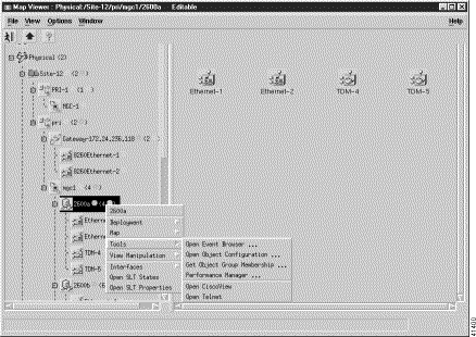
The Performance Manager can be accessed from pop-up menus on selected objects in the following applications:
Step 2 Place the cursor over the object.
Step 3 Press and hold the right mouse button.
Step 4 Move the cursor until the Tools option is highlighted, then highlight the Performance Manager option, as shown in Figure 7-3.
Step 5 Release the right mouse button.
You see the Performance Manager screen shown in Figure 7-4.
From the Performance Manager screen you can:
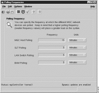
You can set the polling frequency for the various types of devices. While you can specify a separate polling frequency for the Cisco SLTs, the LAN switches, and the Cisco MGC hosts, you cannot set a separate polling frequency for an individual device.
CMNM predefines which performance statistics are collected and simply processes whatever data is available. However, the Cisco MGC host allows you to change these defaults by editing the
Cisco MGC host filter file perfMeasFilters. Use the following commands:
install directory/config/hostController
Measurements can be turned on or off by commenting out the line with # or by deleting the line.
You can define the polling frequency for the various devices, but you should not set the CMNM polling frequency to be less than the Cisco MGC host polling frequency. However, you can increase the CMNM polling frequency so that not all of the Cisco MGC host performance files are processed. For example, you can set Cisco MGC host performance data collection to only once a day.
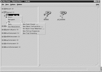
To configure the polling frequency:
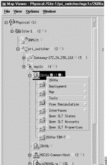
Step 2 Right-click to display the pull-down menu, select Tools, then Open Polling Frequencies as shown in Figure 7-5.
You see the screen in Figure 7-6.
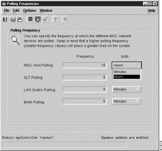
Step 3 Select a polling frequency from the menu. To change from minutes to hours, select from the pull-down menu, as shown in Figure 7-7.
Step 4 To save the polling frequencies you just set, click the Save icon as shown in Figure 7-8.
By default, performance data is not collected for any object. When an object is first deployed in CEMF, it is in the normal state; no performance polling is done. To enable performance polling, you must transition the object into the polling state. This is done using the dialogs posted from the object. CMNM allows you to transition either a single object or a group of objects between the normal and polling states.
When an object is polling, its icon is augmented with a small anotation. Each LAN switch, Cisco SLT, and common Cisco MGC host object has this icon when polling. In addition, the Cisco MGC node object has the polling icon if any of its children are doing polling. In this way, the states of the Cisco MGC subobjects are reflected up to the Cisco MGC node object.
CMNM uses many different indicators to indicate the logical state of a device. On the right side of the Map Viewer, the icon representing each device is shown. For some states, a small symbol is placed near the top of the icon to indicate a logical state. In addition, cross-hatching is used to indicate state information.
Table 7-5 shows the different logical states.
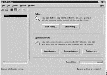
To place a device into a polling state so that data can be collected (this example uses the Cisco SLT, but the procedure is the same for each device):
You see the screen in Figure 7-10.
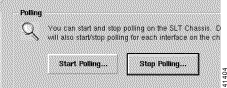
Step 2 Click Start Polling.
You see the screen in Figure 7-11.
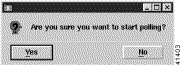
Step 3 Click Yes to proceed.
To stop polling at anytime during the process, click Stop Polling, as shown in Figure 7-12.
|
Note Starting and stopping polling on the Cisco MGX 8260, Cisco SLTs, and LAN switch also starts or stops polling for each interface on the chassis. |
|
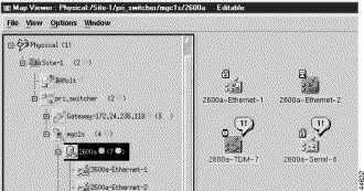
Note When polling is taking place, a sheet with an arrow pointed up appears just above the network or object icon. Figure 7-13 shows the 2600a-Ethernet-1 and 2600a-Serial-8 in polling states. |
While the active Cisco MGC host is being polled, you can also poll other devices on demand by clicking Poll Now.
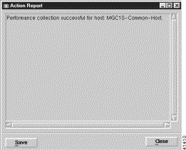
An action report is presented when polling is complete, as shown in Figure 7-14.
You can commission or decomission devices such as the Cisco SLT, LAN switch, Cisco MGX 8260, BAMS, and Cisco MGC host. On the States screen, there are two buttons: one to decommission the device and the other to commission it. There is also a Rediscover button. See Figure 7-10.
Decommissioning a device prevents it from being presence polled or performance polled. A device in the decommissioned state still processes traps, but a presence poll alarm is cleared. Commissioning it brings it back on the network so that it starts presence polling.
Rediscover performs subrack discovery on the device and synchronizes all of the network interfaces and IP addresses.
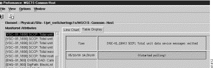
CMNM generates simple graphs of performance data (single counter, single object). These screens show the performance data in tabular, near real-time format for SS7, SS7 Link, SS7 Link Set, Voice Traffic, and Interface Utilization measurements. The performance counters associated with these measurements include, but are not limited to:
To view performance data, you need to select:
Step 2 From the Monitored Attributes list, select the attribute to be monitored.
|
Note You can select multiple attributes in a list by holding down the Shift key and selecting attributes in the list. You can select multiple individual attributes by holding down the Ctrl key and clicking individual items. The information for all selected attributes is shown in the Table Display. Only the first selected attribute is shown in the Line Chart or Bar Chart. |
Step 3 In the Start Date data entry boxes, enter the date the view of the performance statistics has to start from. The format is mm/dd/yyyy.
Step 4 You set a start time and an end time using 24-hour notation. The times are inclusive. In the Start Time data entry boxes, enter the time the view of the performance statistics has to start on the Start Date.
Step 5 To set the End Date you have two options:
In the End Date data entry boxes, enter the date the view of the performance statistics has to stop at. The format must be mm/dd/yyyy or select the Now check box to view the data from the selected start date to the current time. By selecting this option, you do not have to update the End Date and End Time fields.
Step 6 To set the End Time you have two options:
In the End Time data entry boxes, enter the time the view of the performance statistics has to stop on the End Date or select the Now check box to view the data from the selected start date to the current time. By selecting this option, you do not have to update the End Date and End Time fields.
Step 7 From the Interval pull-down menu, select the summary interval to be used. This varies according to the attribute selected. The summary interval is the period of time over which the rule is applied. This pull-down menu always contains the option to select raw. This displays the data in raw format, which is performance data in its most detailed format (not summarized).
|
Note When raw is selected, the Bar Chart view is not available and the Summary Rule option is grayed out. |
Step 8 From the Rule pull-down menu, select the summary rule to be used. This gives you the option to summarize data to a lower granularity as follows:
|
Note The Refresh button is blue when it is available for selection. It is grayed out when not available. The Refresh button is available for selection when Now is selected, or when any criteria has changed and you have moved the cursor away from the changed value by clicking the Tab key or by using the mouse. |
|
Note SNMP data (that is, data collected from the Cisco SLT and LAN switch) is refreshed in near real-time. When data is collected from the active Cisco MGC host, you can manually collect and display the current performance data by clicking Refresh. Refresh simply refreshes the Data view to display the latest data collected during polling. To update the data, you must start polling again. |
By default, a line chart of the performance information, to date, is displayed. You can view performance information in the following formats:
The performance information displayed corresponds to the attributes' raw values. If a summary period is selected, the information is displayed according to the Summary Rule. No summary period is associated with raw data.
|
Note In some circumstances, an object may fail to be polled. All missed polls are indicated on graphs and charts by yellow points that show the last valid value collected. A missed poll affects the summary data, and the data should not be relied upon. |
CMNM graphs and charts also indicate when an attribute started and stopped being polled due to history storage criteria being added, edited, or removed. Start and end polling events are shown in charts and tables:
You can view raw data as it is received without any summarization. History storage criteria define which attributes are to be monitored on specified objects. When these objects are polled, the retrieved data is stored by CEMF and can be viewed using the Performance Manager. This data is raw data. History storage criteria may also optionally specify summary intervals and rules to be applied to the raw data. The resultant data is summarized data.
|
Note The Summary Rule option and the Bar Chart view are not available when the option to view raw data is chosen. |
Step 2 Choose the desired attributes and set the dates and times, as described in the "Viewing Performance Data" section.
Step 3 From the Summary Interval pull-down menu, select raw.
Step 4 Click Refresh.
The new performance information displayed corresponds to the attributes value returned during the raw period.
|
Note The Refresh button is blue when it is available for selection. It is grayed out when not available. The Refresh button is available for selection when Now is selected or when any criteria has changed and you have moved the cursor away from the changed value by pressing the Tab key or by using the mouse. |
You can zoom in, zoom out, and move around the displayed charts by using the keys and mouse buttons described in Table 7-6. Note that you must select a chart before invoking these actions.
Table 7-6 Chart Viewing Actions
| Press | Action |
Clicking and dragging with the left mouse button over an area zooms in on that section of the chart. You cannot zoom in on a chart that has a scroll bar. |
|
Takes the view back one zoom level after zooming in using the left mouse button. |
You can choose to annotate a line chart with color-coded points that represent the polling status. You can also show the values associated with each point.
Step 2 From the View menu, select Values. This option shows the values associated with each point, which are presented in tabular form in the Table Display.
The values are shown on each chart until the item is deselected in the View menu.
Performance data is saved in a log. To view data from past pollings:
Step 2 Click Refresh.
CMNM allows you to specify how long performance data should be kept in the database. You can also specify roll-up rules and other actions that should be taken on performance data after a set length of time.
CEMF manages a database of performance data values, and ensures the database does not grow indefinitely. This is achieved by purging data that is deemed to be old. Several rules are used to determine what data should be purged based on the concept of samples. A sample is either a collection of raw data, or a collection of data that has been summarized using one summary rule for one summary interval.
The attributeHistoryServer.ini file, described in Table 7-7, controls the behavior of the performance purging mechanism:
minValueCount = 50
maxValueCount = 1000
minRawDataAge = 60
Table 7-7 attributeHistoryServer.ini file Attributes
| Parameter | Description |
Specifies the minimum number of values to be kept for each sample. Data is never removed from a sample if doing so would result in that sample having fewer than this number of values. This value is set to 50 on a standard CEMF installation. |
|
Specifies the minimum age of raw data (in seconds) that must be kept. Raw data younger than this age is never removed. This value is set to 60 on a standard CEMF installation. For example, if the system has just received 100 changes to an attribute in the 40 seconds preceding a purg,e then the last 100 values would be kept and not just the last 50. |
|
Specifies the maximum number of values to be kept for each sample. Whenever this number of values is reached for a sample, values are removed until either of the first two settings would be breached if any more were removed. This value is set to 1000 on a standard CEMF installation. |
In some cases, these three settings may conflict with history-storage-criteria summary intervals. For example, if the history storage criteria specifies that only daily summaries are to be generated, but the purging criteria specify that one full day's worth of raw data is never available, then the daily summaries could not be generated if the purge settings were followed. In such cases, data is not purged until summaries that depend on that data have been generated.
These values can be modified using the historyAdmin utility. However these values have a significant effect on database size and performance. As such, care must be taken when changing these parameters, because the settings have a direct association with overall disk requirements.
|
Note For information on configuring how alarms are stored and deleted, see the "Setting How Long Alarms Are Stored" section. |
You can print performance statistics from the Performance Manager, either as a chart or as a table. A chart prints out the information that can be seen in the window. A table prints out all of the performance statistics in a plain text format.
The output is printed by the default printer setup on your network.
Step 2 From the File menu, select Print. Choose either As Chart or As Table.
![]()
![]()
![]()
![]()
![]()
![]()
![]()
![]()
Posted: Thu Feb 13 11:55:55 PST 2003
All contents are Copyright © 1992--2002 Cisco Systems, Inc. All rights reserved.
Important Notices and Privacy Statement.