cc/td/doc/product/access/sc
hometocprevnextglossaryfeedbacksearchhelp
PDF

Table Of Contents

Cisco SS7/CCS7 Dial Access Solution System Integration Guidelines

Terminology

SS7 Overview

Point Codes

Reference Documentation

Cisco SS7/CCS7 Dial Access Solution Overview

Architecture

Benefits

Cisco SS7/CCS7 DAS Operations

Reference Documentation

Features and Benefits

Cisco SS7/CCS7 Solution Features and Benefits

Signaling Controller Features

Management Features

Software Requirements

Hardware Components

Cisco SC22XX Signaling Controller

Network Access Servers

Network Element Management System Server

Authentication, Authorization, and Accounting and Network Management Servers

Cisco SC3640

Backhaul Router

Designing Your Network

Network Engineering Assumptions

Traffic Engineering

Routing Control and Data Traffic

Designing an IP Subnetting and Addressing Plan

Reference Documentation

Preparing for Implementation of Cisco SS7/CCS7 DAS

SS7 and PSTN Data

IP Data

Signaling Controller Configuration Information

Implementing the Cisco SS7/CCS7 DAS

Sequence of Implementation

Hardware Connections

Installing Software

Configuring the Cisco SC22XX Signaling Controller

Configuring the NAS

Configuring Other Components

Getting Help

Where to Get the Latest Version of This Guide

Signaling Controller Documentation Roadmap

Hotlinks to Online Documentation

If You Need More Information

Cisco Connection Online

Documentation CD-ROM


Cisco SS7/CCS7 Dial Access Solution System Integration Guidelines


Caution   This is a legacy document that contains outdated information. Use the document as an example of an integrated system, but not as a guarantee of compatibility. Please send any comments to pgw-techpubs@external.cisco.com.

The Cisco SS7/CCS7 Dial Access Solution (DAS) provides centralized functions for adding Signaling System #7 (SS7) interfaces to large dial Points of Presence (POPs). This Non Facility Associated Signaling (NFAS) functionality provides a full integration of dial access capabilities within the circuit switched network infrastructure and provides significant savings on switching interface costs while simultaneously reducing trunking costs. Using the NFAS functionality means that all your T1 and E1 channels are used for voice and data while the associated signaling is carried separately over the SS7 network. In addition, you have the ability to scale your network cost-effectively from a few hundred to thousands of ports because you do not need to add a D channel for every additional port.

The Cisco SS7/CCS7 DAS consists of the Cisco SC22XX signaling controller working together with the Cisco network access servers (NAS), such as the Cisco AS5200, Cisco AS5300, or Cisco AS5800 to create a system that emulates a terminating or originating end-office telephone switch in the Public Switched Telephone Network (PSTN).

Terminology


Note   Refer to for a graphic representation of links and other telephony terminology.


Table 1 Terminology 

Acronym
Description

AAA

Authentication, Authorization, and Accounting. Set of functions on the NAS providing authentication, authorization, and accounting for system and network resources.

A-link

Access link. A signaling link between an STP and SSP or an STP and SCP in the same SS7 network.

ANSI

American National Standards Institute. Voluntary organization composed of corporate, government, and other members that coordinates standards-related activities, approves U.S. national standards, and develops positions for the United States in international standards organizations. ANSI helps develop international and U.S. standards relating to, among other things, communications and networking. ANSI is a member of the IEC and the ISO. See also IEC and ISO.

ASP

Auxiliary Signal Path. A link between signaling controllers that allows them to exchange signaling information that is incompatible with the PSTN backbone network protocol; used to provide feature transparency.

B-link

Bridge link. A signaling link between two nonmated STPs at the same hierarchy in the same SS7 network.

CCS

Common channel signaling. Signaling system used in telephone networks that separates signaling information from user data. A specified channel is exclusively designated to carry signaling information for all other channels in the system. See also SS7.

CCS7

Common channel signaling 7. This is the North American version of SS7.

CEF

Cisco Express Forwarding. Also known as FIP. See FIP later in this table for details.

C-link

Cross link. A signaling link between two mated pairs of STPs in the same SS7 network.

CLI

Command Line Interface; the basic Cisco IOS configuration and management interface.

COT

Continuity Test. A test used to verify that an ISDN bearer circuit is functioning correctly; generally involves a combination of tone generation, tone detection, and loopback circuitry to verify physical continuity of a circuit; COT may be invoked automatically by network elements in an SS7 network.

D-link

Diagonal link. A signaling link between two nonmated STPs at the different hierarchical levels in the same SS7 network.

DS0

A 64-Kbps digital TDM channel.

DS0A

A 56-Kbps digital circuit running over twisted-pair, with an included composite clock signal; one of the styles of physical interfaces used in North America for SS7 A-links.

DSP

Digital Signal Processor. Many firmware functions of a NAS are performed by DSPs which are generally provisioned as banks of shared resources among all the DS0s. Typical DSP functions include: data modems, voice CODECs, fax modems and CODECs, and low-level signaling (such as CAS/R2).

E-link

Extension link. A signaling link between an STP and SSP or an STP and SCP in different SS7 networks.

FCC

Federal Communications Commission in the United States. This U.S. government agency supervises, licenses, and controls electronic and electromagnetic transmission standards.

FIP

FDDI Interface Processor. (Also known as CEF.) Interface processor on the Cisco 7000 series routers. The FIP supports SASs, DASs, dual homing, and optical bypass, and contains a 16-mips processor for high-speed (100-Mbps) interface rates. The FIP complies with ANSI and ISO FDDI standards.

F-link

Fully associated link. A signaling link between two SSPs in the same SS7 network.

IN

Intelligent Network. The IN resides within the PSTN and provides telecommunications companies with the ability to create and deploy services independent of the switch manufacturers. The IN is a software platform that telcos use to create products and services for customers such as 800 numbers, caller ID, and voice mail. The IN works in conjunction with the SS7 network.

ISO

International Organization for Standardization. International organization that is responsible for a wide range of standards, including those relevant to networking. ISO developed the OSI reference model, a popular networking reference model.

ISP

Internet service provider. Company that provides Internet access to other companies and individuals.

ISUP

Integrated Services Digital Network (ISDN) User Part. The protocol used to set up, manage, and release trunk circuits that carry voice and data between terminating line exchanges (for example, between a calling party and a called party). ISUP is used for both ISDN and non-ISDN calls. However, calls that originate and terminate at the same switch do not use ISUP signaling.

IXC

Inter-Exchange Carrier. Common carrier providing long distance connectivity between LATAs. The three major IXCs are AT&T, MCI, and Sprint, but several hundred IXCs offer long distance service in the United States.

LATA

Local access and transport area. Geographic telephone dialing area serviced by a single local telephone company. Calls within LATAs are called local calls. There are well over 100 LATAs in the United States.

Load balancing

In routing, the ability of a router to distribute traffic over all its network ports that are the same distance from the destination address. Good load-balancing algorithms use both line speed and reliability information. Load balancing increases the use of network segments, thus increasing effective network bandwidth.

LEC

Local Exchange Carrier. Local or regional telephone company that owns and operates a telephone network and the customer lines that connect to it.

MDL

Message Definition Language. A high-level language used to specify protocols and protocol conversion operations on the signaling controller system.

MML

Man-Machine Language. The command interface for configuring and managing the signaling controller.

NAS

Network access server. A Cisco platform that provides modem and ISDN services for connecting to the network.

PC

Point Code. Unique hierarchical address for a signaling point in an SS7 network.

POP

Point of presence. A location where a service provider has a dial-up access presence.

POTS

Plain Old Telephone Service.

PSTN

Public Switched Telephone Network.

RADIUS

Remote Access Dial-In User Service. Protocol for managing an AAA database on a server.

SCP

Service Control Point. SCPs are databases that provide information necessary for special call processing and routing, including 800 and 900 call services, credit card calls, local number portability, and advanced call center applications.

SP

Signaling Point. A node in a SS7 network.

SS7

Signaling System 7. Standard CCS system used with BISDN and ISDN. Developed by Bellcore. See also CCS.

SSP

Service Switching Point. Telephone switches (Class 5 end offices or Class 4 tandems) equipped with SS7 software and signaling links are designated as SSPs. They originate, terminate, or transmit switch calls based on SS7 signaling procedures through interaction with STPs, SCPs, and other SSPs.

STP

Signal Transfer Point. STPs receive and route incoming signaling messages toward the appropriate destination. They function as packet switches, terminating the 56 to 64-Kbps SS7 (packet data) signaling links. Due to the critical nature of the signaling network, SCPs and STPs are deployed in mated pairs.

TACACS+

Terminal Access Controller Access Control System Plus. Proprietary Cisco enhancement to TACACS. Provides additional support for authentication, authorization, and accounting. TACACS is an authentication protocol, developed by the DDN community, that provides remote access authentication and related services, such as event logging. User passwords are administered in a central database rather than in individual routers, providing an easily scalable network security solution.

TDM

Time Division Multiplexing. Technique in which information from multiple channels can be allocated bandwidth on a single wire based on preassigned time slots. Bandwidth is allocated to each channel regardless of whether the station has data to transmit.

WFQ

Weighted Fair Queuing. Congestion management algorithm that identifies conversations (in the form of traffic streams), separates packets that belong to each conversation, and ensures that capacity is shared fairly between these individual conversations. WFQ is an automatic way of stabilizing network behavior during congestion and results in increased performance and reduced retransmission.


SS7 Overview

SS7 is the international standard for the common channel signaling system. SS7 defines the architecture, network elements, interfaces, protocols, and the management (MGMT) procedures for a network which transports control information between network switches and between switches and databases. The North American version is also sometimes referred to as CCS7. SS7 is used between the PSTN switches replacing per-trunk in-band signaling, LEC switches, IEC switches, and between LEC and IEC networks.

The SS7 is implemented on a separate data network within the PSTN and provides call setup and teardown, network management, fault resolution, and traffic management services. The SS7 network is solely used for network control and the only data sent over it is signaling messages. (Note that the term SS7 can be used to refer to the SS7 protocol, the signaling network, or the signaling network architecture.)

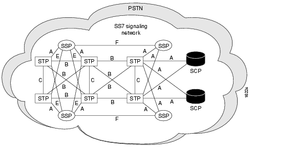
The SS7 protocols that convey signaling information between switching systems (called signaling points) in the PSTN are carried on a special overlay network used exclusively for signaling. The signaling points use routing information in the SS7 signals to transfer calls to their final destinations.

Figure 1 SS7 Signaling Network

The SS7 architecture consists of the following signaling points (as shown in ):

Service Switching Points (SSPs) are telephone switches equipped with SS7 software and signaling links. Each SSP is connected to both STPs in a mated pair.

Signaling Transfer Points (STPs) receive and route incoming signaling messages toward their destinations. STPs are deployed in mated pairs and share the traffic between them.

System Control Points (SCPs) are databases that provide the necessary information for special call processing and routing, including 800 and 900 call services, credit card calls, local number portability, cellular roaming services, and advanced call center applications.

As you can see in , the SCPs and STPs and their links are deployed as mated pairs because of the critical nature of the signaling network.

The SS7 network features include:

Control over the establishment of calls across the PSTN.

Routing, billing, information exchange functions, specialized call treatments, and enhanced routing.

Common channel signaling in which signaling information for different connections travels on separate dedicated signaling channels.

Voice and data connections that travel on bearer channels.

Point Codes

Each signaling point (also called an SS7 node) in the SS7 network is identified with a unique address called a point code (PC). North American point codes are 24-bit and international point codes are 14-bit. (Note that China uses a special ITU 24-bit format that is incompatible with the North American and other international point codes.) PCs are carried in signaling messages exchanged between signaling points to identify the source and destination of each message. PCs are managed by the government agency that supervises, licenses, and controls electronic and electromagnetic transmission standards in your country (for example, the FCC in the U.S.). Note that there could be two separate agencies managing policy and providing licenses in your country.

Figure 2 Point Codes in the SS7 Network

As the traffic is shared between both pairs in the links, the links are referred to as linksets.

The PC is a hierarchical address consisting of:

Network Code identifies a signaling network.

Network cluster identifies a cluster of nodes belonging to a signaling network. For example, you can address a group of nodes using the same mated pair of STPs as a network cluster.

Network cluster member identifies a single signaling point within a cluster.

In (showing a North American setup), the PC 171.16.6 used for the one of the mated STPs consists of the following elements:

171 is the Network Code.

16 is the Network Cluster ID. For example, if you had 25 STP pairs nationwide, this octet would represent the STP pair number 16.

6 is the end node which is connected to the network cluster, in this case the SP.

The network indicator determines the type of call that is being placed:

Calls with an indicator of 0 are international bound and are immediately forwarded to an STP pair that is an international gateway.

Calls with a network indicator of 2 are national calls and are routed through the national network.

The network indicator of national spare (3) is used in countries where multiple carriers share point codes. In this case, networks are differentiated by this indicator. For example, in Germany the Deutsche Telekom (a primary carrier) has a PC of 1.244.3 (NI 2). mediaWays has the same PC but uses the NI of 3. Calls for mediaWays are addressed with the same PC but with the NI of 3.

Reference Documentation

See the following publications and web site for a comprehensive overview of SS7 and other information related to the Cisco dial access solution:

Black, U. ISDN and SS7 Architecture for Digital Signaling Networks. Upper Saddle River, New Jersey: Prentice Hall PTR; 1997

Bellamy, J. Digital Telephony, Second Edition. New York, New York; John Wiley and Sons, Inc.; 1991.

UNIX System Administration Handbook, Second Edition. Prentice Hall; 1995.

http://www.iec.org/. Click Training, Web ProForum Tutorials, Communications Networks, and then scroll down the list and click Signaling System #7 (SS7).

Other web sites listed in the section, " Hotlinks to Online Documentation."

Cisco SS7/CCS7 Dial Access Solution Overview

Architecture

The two primary components of the Cisco SS7/CCS7 DAS are the Cisco SC22XX signaling controller, which works together with the Cisco NASs (Cisco AS5200, Cisco AS5300, or Cisco AS5800) to create a system that emulates a terminating or originating end office in the PSTN. Note that in the SS7 architecture, the Cisco SS7/CCS7 DAS is an SSP.

The Cisco SS7/CCS7 DAS components include:

Cisco SC22XX signaling controller to provide connection to the SS7 network and the NASs. In addition to SS7 protocol functions, the signaling controller provides system resource management (including keeping track of circuit IDs for ports on the NASs for assigning calls), call control (including originating and terminating call processing/signaling), managing resource availability, usage measurements for accounting and management purposes, and alarms.

NASs, such as the Cisco AS5200, Cisco AS5300, or Cisco AS5800 to terminate the ISUP trunks (bearer channels). The ISUP trunks are T1 or E1 PRI interfaces.

Cisco SC3640 to provide SNMP offloading, system logging, TFTP services, and network documentation services if you are using the Cisco AS5800 in your DAS. In addition, the Cisco SC3640 provides a direct connection (via the console port) to the signaling controller, NAS, AAA server, network management server, NEMS server, and backhaul router so that you can access and manage the devices directly if the network goes down.

AAA and network management servers to provide security and network management.

Backhaul router to provide a connection to the ISP backbone, which provides a connection to the Internet.

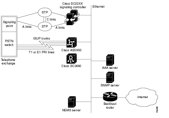
shows the setup for a Cisco SS7/CCS7 DAS with mated STP pairs using A links. In this redundant system, the STPs share the load and protect your system against failure by diverting the traffic around the failure. This setup includes only one NAS, and all the DAS components are located on the same subnet.

Figure 3 Cisco SS7/CCS7 DAS with Single NAS

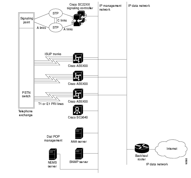
shows a setup with multiple NASs and two subnets. One subnet supports the signaling controller, NASs, management servers (AAA, SNMP, network management, and NEMS), and the Cisco SC3640. The second subnet provides a fast Ethernet connection between the NASs and the backhaul router for WAN access.

Figure 4 Cisco SS7/CCS7 DAS with Multiple NASs

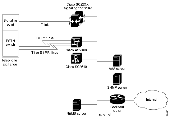
shows the setup for a Cisco SS7/CCS7 DAS using direct F-links with no STP redundancy. This setup is used typically in the lab to test functionality.

Figure 5 Cisco SS7/CCS7 DAS with F-Links

Benefits

Using the Cisco SS7/CCS7 DAS provides the following benefits:

SS7 interfaces on NASs allow an ISP to provide wholesale dial services, dialup VPNs, Internet access, and voice services while interconnecting as a carrier. The ISP benefits from new revenue, lower operating costs, scaling, and reciprocal compensation benefits.

Address voice network congestion by using the SS7 interfaces to make features, such as rerouting on overflow conditions and the use of IN functions possible, which further drives down operations costs.

Install an SS7 POP in a new location without a switch.

Integrate the NASs directly into the SS7 network using the Cisco SS7/CCS7 DAS and thus remove the need for two switch ports on the PSTN circuit switch for each NAS port installed.

Increase the signaling to bearer ratios thus decreasing the signaling channels needed and the complexity.

Reduce network resource usage by using the SS7 interface to find the best routing in the network for the bearer channels before connecting a call. In the case of a PRI connection to the network, bearer channels must be established through to the end switch and the PRI trunk before returning the busy and clearing the network resources. Using SS7, the signaling knows that the termination trunks are busy and does not establish the bearer channel routing thus freeing network resources.

Cisco SS7/CCS7 DAS Operations

This section provides a brief overview of the following concepts and functionality used in the Cisco SS7/CCS7 DAS:

Signaling Controller and NAS Communication Protocols

Understanding the Redundant Link Manager (RLM)

Understanding the Failover System

Understanding Signaling Controller Configuration Files

The PSTN SS7 network routes SS7 messages to the Cisco signaling controller, which converts the SS7 messages to a protocol recognized by the Cisco NASs. (The Cisco signaling controller appears as a signaling point on the SS7 network.) The NASs appear as a telephone switch to the PSTN thus bypassing the local exchange carrier and the need to purchase ports on the telephone central office (CO) switch.

The Cisco signaling controller and NASs communicate, via an IP network, using an extended Q.931 protocol.This allows the signaling controller to provide call control for multiple NASs, which can be located in the same or different geographical sites.

Signaling Controller and NAS Communication Protocols

The Cisco control protocol architecture for communication between the signaling controller and NASs provides reliable signaling over an IP network and includes these features:

Maintains all current NAS functionality.

Supports Continuity Check (COT) and other maintenance functions.

Supports multiple links between the NASs and signaling controllers for full recovery in case of failures.

Supports LAN or WAN IP network connectivity with potentially diverse networks for reliability.

The protocol stack is shown in .

Table 2 Protocol Stack

Extended Q.931

Q.921

UDP

IP


Extended Q.931 provides call control, COT functionality, and maintenance functions.

Q.921 provides sequencing and retransmission for messages.

User Datagram Protocol (UDP) provides the transfer of signaling messages across the LAN or WAN subnetworks connecting the NASs to the signaling controller.

IP provides addressing, type-of-service specification, fragmentation and reassembly, and security.

Understanding the Redundant Link Manager (RLM)

The Cisco Redundant Link Manager (RLM) provides link management over multiple IP networks so that your Cisco DAS can tolerate a single point of failure. Note that your DAS must be implemented using two or more subnets to use this failover functionality (see "Routing Control and Data Traffic" for details).

Using the RLM functionality, the Q.931 signaling protocol and other proprietary protocols are transported on top of multiple redundant links between the signaling controller and the NASs. In addition to this, RLM opens, maintains, and closes multiple links, manages buffers of queued signaling messages, and monitors whether links are active for link failover and signaling controller failover. The RLM goes beyond Q.921, because it allows for future use of different upper layers, and more importantly, allows for multiple, redundant paths to be treated as one path by upper layers.

See the publication Redundant Link Manager Feature at this url for details:

http://www.cisco.com/univercd/cc/td/doc/product/access/sc/r2/ios_r2/index.htm

Understanding the Failover System

The Cisco signaling controller includes a failover system (also called a redundant system) to protect your system against failures and downtime. The failover system consists of two servers connected via IP, serial, or a combination of the two types of interfaces, as shown in . (For a graphical representation of the redundant Cisco SC2200 Signaling Controller, see .) One server functions as the active host while the other server functions as the standby host. The failover system provides a seamless transition to the standby host in case of system failures.

The active host maintains communications between the active and standby hosts. The standby host constantly checks the active host for new and changed configurations and updates itself on a regular basis. Thus, when the standby host becomes the active, its configuration mirrors that of the former active host.

Figure 6 Failover Processes on the Signaling Controller Hosts

You can set the following switches for the failover controller. Note that these switches apply to the physical links only. If there is an event failure on the active host, the standby host starts call processing functions but the physical links might not return to service (depending on the switch setting).

Table 3 Failover Switches 

Component
Description

Auto

Transitions to the standby host when an alarm occurs.

A

A is the only host with no switchover.

B

B is the only host with no switchover.


Understanding Signaling Controller Configuration Files

The signaling controller is configured and managed using a series of configuration (.dat) files. You create these configuration files using the signaling controller configuration tool, a graphical user interface, on the NEMS server. The files contain all the configuration information required by the signaling controller. The NEMS server creates a folder for each signaling controller in the c:\Lightspeed\TransPathCM\install directory. These files are used by the signaling controller to process the network data. The configuration tool also provides a configuration library utility you can use to back up and restore configurations.

Mapping NAS Bearer Channels to SS7 Signaling Links

The signaling controller maintains an internal mapping of the PSTN and NAS bearer circuits in the bearchan.dat, sigchan.dat, and sigchanip.dat files. This allows the signaling controller to determine which bearer circuit to use for the outgoing part of a call when a call originates from the PSTN or NAS. Each SS7 connection is identified using these three codes:

Originating Point Code (OPC)

Destination Point Code (DPC)

Circuit Identification Code (CIC)

The signaling controller uses the SS7 circuit identification information to uniquely identify each bearer circuit, which is identified by:

Span ID (the trunk ID)

Timeslot within the trunk

The signaling controller uses a set of signal channels to communicate with the NASs. Each signal channel is associated with a set of bearer channels that might be controlled by that signal channel.

Part of your configuration task for the signaling controller is to associate the NAS resources with the signaling controller. The DS0s are identified in the NAS as a two-level scheme consisting of trunk/timeslot. The trunk identifies the particular TDM multiplexed interface on the NAS (for example, T1/E1, PRI, T3/E3). The timeslot identifies the particular DS0 channel on that trunk. (Note: To make the association task easier, you can use ranges of timeslots.)

When the signaling controller identifies a bearer circuit, the signaling controller can then determine a valid route for signaling messages that control the circuit. Routes are expressed in terms of signal paths. For SS7, each signal path represents an SS7 link set. For the NAS, each signal path represents an IP connection to the NAS. SS7 signal paths use ISUP protocols and NAS signal paths use the Cisco Q.931-based protocol.

The IP address (or DNS name) of the appropriate NAS is associated with each NAS signal path in the signaling controller configuration.

Reference Documentation

See the following publications for detailed information:

Cisco SC2200 Signaling Controller Configuration Tool Guide

Cisco SC2200 Signaling Controller Software Operations and Maintenance Guide

Dial Solutions Configuration Guide

Release notes. Note that release notes are only available through your Cisco representative.

These publications are available online on the Cisco web site or on the Cisco Documentation CD-ROM that arrived with your system. See the section, " If You Need More Information," and " Cisco Connection Online," for details.

Features and Benefits

This section describes the Cisco SS7/CCS7 solution features and benefits, signaling controller features, and the management features supported by both the signaling controller and NASs.

Cisco SS7/CCS7 Solution Features and Benefits

lists the features and benefits for the Cisco SS7/CCS7 solution.

Table 4 Features and Benefits 

Feature
Benefit

Connect access servers directly to PSTN in peer-to-peer interconnect

Reduce network costs

Interconnect with more favorable tariffs and rates

Introduce services such as wholesale dial, VPDNs, and virtual modem pooling

Realize new revenues

Reduce PSTN congestion

Support for co-located and distributed access servers

Savings, scaling, and flexibility

Cisco AS5800, Cisco AS5300, and Cisco AS520 support

Investment in Cisco protected

Terminating and originating switching system functions

Enable new services

Fast time to market

Dial-out and Dial-in

Meet interconnect requirements

Scaling 50,000 DS-0 ports

30 calls per second throughput

108,000 busy hour call attempts

Scale cost-effectively to central-office size

Complete network management

Lower cost of ownership

Can be addressed with up to 6 point codes

Support for 16 simultaneous switch interconnects

Quasi-associated or fully-associated signaling

Complete continuity check (two-wire and four-wire)

NEBS Level 3 compliant

Four Cisco SC2200 platform options (see for details)

Flexible and scalable

Ready for international markets

Meets interconnect requirements

Telco ready

Cost-effective options

Worldwide protocol support with MDL

Ready now

Certifications worldwide

Fast time to market

Software upgrade

Investment protection

Lower cost of ownership

Part of a complete solution with Cisco IOS software

Reliable IP link between Cisco SC2200 and access servers with Redundant Link Manager (RLM)

No single point of failure in connection between access servers and Cisco SC2200

Virtual Private Dial-up Networks (VPDN) with L2F and L2TP

Dial-out for callback and dial-on demand routing (DDR)

Current remote access servers data features

New revenue opportunities

Complete services

Investment protection

Radius or TACACS+ AAA functions, including authentication based on calling or called number

Call detail records for PSTN billing

Meet PSTN requirements to create new service opportunities

Cisco SC2200 features parallel advances in Cisco Dial, ISDN, and routing platforms.

Realize the vision of open packet telephony and new world network architectures


Signaling Controller Features

This section lists the following features for the signaling controller:

Protocols

Physical signaling interfaces

Protocols


Note   New protocols are being added rapidly, so check with Cisco to determine if your protocol is supported.


Table 5 Protocols Supported 

Protocols
Support for...

ETSI ISUP and MTP v.1 & v.2

French ISUP

Dutch ISUP

German ISUP

Italian ISUP

Spanish ISUP

Finish ISUP

Belgian ISUP

Swiss ISUP

Polish ISUP

ITU Q Series ISUP and MTP

Q.700-707 - MTP

Q.761-764, 767 - ISUP

ANSI ISUP & MTP

ANSI ISUP and MTP

Bellcore GRs

Additional protocols

Japan J-TTC ISUP and MTP

BT-NUP

BT-ISUP

Australian ISUP

China TUP

Hong Kong ISUP

Custom ISUPs

NT ISUP (IBN7)


Physical Signaling Interfaces

lists the physical signaling interfaces supported by the signaling controller.

Table 6 Physical Signaling Interfaces 

Interface
Support for...

I/O cards

T1—2 64 Kbps signaling channel per T1

E1—2 64 Kbps signaling channel per E1

V.35-56 or 64 Kbps—2 signaling links per card

Inter-office trunk interfaces

T1—64 Kbps clear channel

E1—64 Kbps clear channel

T3-Channelized interface (Cisco AS5800 only)

COT

Automated maintenance to check circuit attenuation

Evoked within Initial Address Message (IAM) every 10th call

Used in U.S., Canada, and some other countries

Can be turned off within some networks

Signaling link configurations

Quasi-associated signaling (A-Links)

Fully associated signaling (A-Links)

Link-set support

Up to 6 physical links per system (two per I/0 card) for Cisco SC2201 and Cisco SC2202

Up to 14 physical links per system (two per I/0 card) for Cisco SC2211 and Cisco SC2212

Simultaneous connectivity to 16 signaling points simultaneously

Up to 6 point codes assigned to system simultaneously

Platforms

The signaling controller is available in high-availability or simplex configurations on the Sun Solaris Netra DC-powered telco-hardened platforms (NEBS compliant) or the Sun Enterprise 450 AC-powered systems:

Cisco SC2201: single system, NEBS, DC

Cisco SC2202: high availability, NEBS, DC

Cisco SC2211: single system, AC

Cisco SC2212: high availability, AC


Management Features

The Cisco SS7/CCS7 DAS solution includes a set of management applications for the signaling controller and the NASs so that you can manage all the components in your solution as a single system from a common platform.

Signaling Controller Management

provides an overview of the management components of the Cisco signaling controller.

Table 7 Signaling Controller Management Features 

Management Component
Description

Configuration

Use the signaling controller configuration tool (JAVA-based client-server application) to create, modify, and delete system profiles for Cisco SC3640s. The configuration tool resides on the NEMS server, which maintains configurations for the signaling controllers.

Alarms

The signaling controller supports a comprehensive set of alarms (configuration, resource, OS, I/O card, and signaling channel failure and line interface loss of signal). You can customize alarm severity and thresholds to match your carrier's severity level definitions. You can also configure the system to generate real-time alarms to local or remote terminals. All alarms are written to a log file in an uncompressed format for easy retrieval.

Performance Measurement

You can get a variety of usage statistics from the signaling controller. The data is recorded real-time and written to a file. You can specify the statistics to be collected and the time intervals for collection and writing to file. Each performance measurement record includes the start time, duration, measured value, category, and element measured.

Accounting

Every call that passes through the signaling controller produces call detail information. The details include:

CLI pretranslated

CLI posttranslated

Dialed number pretranslated

Dialed number posttranslated

Start, Seizure, Supervision, Disconnect Time stamps

Circuit path information

Call detail records are written to a spool file which is automatically closed at defined intervals or when the file exceeds a specified size. You can also specify to retrieve or send closed files to processing systems.


Network Access Server Management

The Cisco IOS software installed on the NASs provides an array of network management capabilities (described in ) designed to meet the needs of today's large, complex networks. These management features reduce network bandwidth and processing overhead, offload management servers, conserve resources, and ease system configuration tasks. The Cisco integrated management simplifies administrative procedures and shortens the time required to diagnose and fix geographically dispersed networks with a small, centrally located staff of experts. Configuration services reduce the cost of installing, upgrading, and reconfiguring network equipment.

Table 8 NAS Management Features 

Management component
Description

SNMP and RMON Support

NASs are fully manageable using the Simple Network Management Protocol (SNMP) and imbedded Remote Monitoring (RMON) capabilities:

SNMP provides for the collection of information about each controller and interface, which can be polled through any SNMP-compatible network management system.

RMON acts as a remote protocol analyzer and LAN probe.

Using the Alarm RMON group, you can set a threshold on any integer-valued Management Information Base (MIB) variable. When the threshold is crossed, an event, defined in the Event RMON group, is triggered. With these capabilities, the system can detect and analyze overloaded conditions and congestion in real-time.

Network Management Systems

The NASs both support CLI and CiscoView graphical user interface (GUI) for comprehensive, flexible network management.

CiscoView provides dynamic status, statistics, and comprehensive configuration information for Cisco switches, routers, NASs, concentrators, and adapters. It displays a graphical view of Cisco devices, provides configuring and monitoring functions, and offers basic troubleshooting.

Modem Management

Cisco offers two types of modems: basic and managed. Managed modems offer superior reporting and statistics in the CiscoView application, including troubleshooting and monitoring modem connections on individual or groups of modems while calls are in progress.

You can manage modems using the same tools used to manage the rest of the network. In addition, managed modems provide an out-of-band management feature that allows you to reduce problem detection and resolution time from a remote site.

Through out-of-band management, you can view real-time information (for current or previous calls) such as modem modulation scheme, modem protocol, modem EIA/TIA-232 signal states, modem transmit and receive states, and analog signal-to-noise ratio.


Software Requirements

The Cisco SS7/CCS7 dial access solution requires the following software release levels:

Cisco IOS Release 11.3(7)AA or later running on the NASs.

MICA Portware Release 2.6.1.0 running on the NAS modem modules.

Signaling Controller Release 4.2(X).

Hardware Components

The Cisco SS7/CCS7 DAS consists of the following elements (as shown in and ):

Cisco SC22XX signaling controller

NAS

In addition, Cisco provides the following components for managing your DAS solution:

NEMS server

AAA and network management servers

Cisco SC3640

Backhaul router

See the following sections for details.

Cisco SC22XX Signaling Controller

The Cisco SC22XX provides easy scaling to 50,000 DSO ports, resource management, and call control functions. In addition, it supports co-located or distributed dial shelves and SNMP support for alarms. The signaling controller includes the following components:

A scalable, open server

Alarm relay unit (ARU)

Failover controller (or A/B switch)

Patch panel

Serial port expander


Note   The DC power supply and Ethernet (10 or 100 MB) hub are not supplied as a part of the signaling controller system. The Ethernet hub is necessary if you plan on a failover configuration for your signaling controller hosts. You can order these devices from Cisco Systems or supply your own devices.


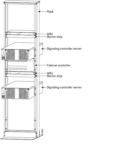
You can order the Cisco SC22XX as a single- or dual-machine for redundancy, as shown in .

Figure 7 Redundant Single-Rack Cisco Signaling Controller

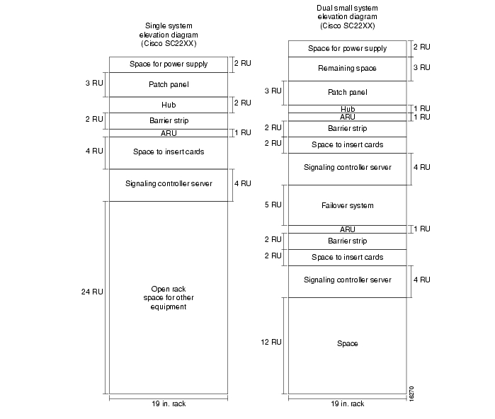
See for a graphical depiction of a single and dual rack setup with single and dual host configurations. lists each element of the vertical rack and the size of each piece of equipment in Rack Units (RUs), where 1 RU = 1.75 inches.

Figure 8 Single and Redundant Cisco Signaling Controller Configurations in Single Racks

Table 9 Rack Units for Equipment 

Equipment Item
Rack Units (1 RU = 1.75 in.)

Reserved for customer-provided power

6 RU

120-ohm patch panel

3 RU

Reserved for customer-provided Ethernet hub

1 RU

Failover control box

5 RU

Barrier strip

2 RU

ARU

1 RU

Serial port expander

2 RU

Signaling controller host

3 RU

Empty space

7 RU


Signaling Controller Hosts

The signaling controller includes a scalable, open host that provides SS7 interfaces, alarms, and a reliable IP link between the signaling controller and NASs. This release offers the option of one of these Sun hosts: Sun Ultra Enterprise 450 or Sun Netra 1120t.

Sun Ultra Enterprise 450

The Sun Ultra Enterprise 450 is a high performance, shared memory, multiprocessing general purpose Sun Ultra SPARC server. It supports up to four 400 MHz processors and is rack mountable. It has 10 PCI slots, of which 7 accept E1, T1, or V.35 cards. It is used in the Cisco SC2211 and Cisco SC2212 SS7/CCS7 DAS solutions.

Figure 9 Sun Ultra Enterprise 450 (Signaling Controller Host)

lists the Sun Enterprise 450 specifications.

Table 10 Sun Enterprise 450 Specifications for Cisco SC2211 and Cisco SC2212 

Feature
Description

Processor

300-MHz UltraSPARC-II modules with on-board E-cache

Main memory

16 DIMM module slots; four banks of four slots
Accepts 32-, 64-, or 128-MB DIMMs (256 MB when available)
128 MB to 4 GB total memory capacity

Operating system

Sun Solaris 2.5.1

Interfaces


Serial

Two EIA-232D or EIA-423 serial ports, DB-25 (requires Y-type splitter cable); 1 50 to 384 Kbps synchronous, 1 50 to 460.8 Kb asynchronous

Parallel port

2-MB/sec Centronics compatible bidirectional EPP port; DB25

Ethernet

One 10/100-Mb/sec autoselect port; RJ-45 or MII

Keyboard and mouse

One standard keyboard/mouse port; mini DIN-8

PCI

Three slots for 32-bit 33-MHz 5V PCI cards
Four slots for 32- or 64-bit 33-MHz 5V PCI cards
Three slots for 32- or 64-bit 33- or 66-MHz 3.3V PCI cards

SCSI

1, 3, or 5 40-MB/sec Ultra SCSI-3 buses for internal disks
One 20-MB/sec Fast/Wide SCSI-2 bus for CD-ROM and tape; 68-pin external connector

Environment


Power supplies

One, two, or three modular, N+1 redundant, hot-swap, universal input (1 supply standard)

AC

Power 90-264 Vrms, 47-63 Hz

AC Service requirement

15A at 110V, 7.5A at 240V

Maximum power consumption

1664 watts

Heat output

5680 BTU/hour maximum

Operating temperature

5° to 40°C (41° to 104°F) at 20 to 80% relative humidity, noncondensing

Non-operating temperature

-20° to 60°C (-4° to 140°F) at 5 to 93% relative humidity, noncondensing

Regulatory Compliance and Safety Specifications (Meets or exceeds the following specifications)

Safety

UL 1950, CSA 950, TUV EN60950, IEC950

RFI/EMI

FCC Class B, DOC Class B, EN55022/CISPR22 Class B, VCCI Class II

Immunity

EN50082/IEC-1000-2, IEC-1000-3, IEC-1000-4, IEC-1000-5

Harmonics

EN61000-3-2

Dimensions and Weights


Height

22.87 in. (58.1 cm)

Width

17.64 in. (44.8 cm )

Depth

27.40 in. (69.6 cm)

Weight

205 lb (94.0 kg)

Rack mounting

Sun Enterprise 450 can be mounted in a standard 19-in. EIA rack with minimum depth of 30 in. (675 mm)


Sun Netra 1120t

The Sun Netra is a general purpose Sun Ultra SPARC server. It has four PCI slots, of which three accept E1, T1, or V.35 cards. The Netra is rack-mountable and is NEBS and ETSI compliant.

Figure 10 Sun Netra 1120t (Signaling Controller Host)

lists the Sun Netra 1120t specifications.

Table 11 Sun Netra 1120t Server Specifications for Cisco SC2201 and Cisco SC2202 

Feature
Description

Processor

One SPARC Version 9, 300-MHz UltraSPARC-II processor

Main Memory

512 MB maximum (with 32-MB SIMMs in pairs)
1 GB maximum (with 64-MB SIMMs, in pairs)
2 GB maximum (with 128-MB SIMMs, in pairs)
(Note: Install SIMMs in sets of four for best system performance)

Operating System

Sun Solaris 2.5.1

Interfaces


Network

Ethernet/Fast Ethernet, STP (10 BaseT and 100 BaseT) or MII for external transceiver

I/O

40-MB/sec UltraSCSI (SCSI-3 synchronous

Serial

Two EIA/TIA RS-232C or EIA/TIA RS-423 serial ports (DB25)

Parallel

Centronics-compatible parallel port (DB25)
(ECP-mode capable)

PCI

Four full-size PCI with PCI specification version 2.1; three slots operating at 33 MHz, 32- or 64-bit data width; one slot operating at 33 or 66 MHz

Alarms Card

DB15-pin connector; three dry contact outputs (minor, major, critical); external reset input

Environment


DC power

-48/60 VDC nominal, 350W, dual input

Operating

5° to 40°C (41° to 104°F) 5 to 85% relative humidity, noncondensing, subject to a maximum absolute humidity of 0.024 kg water/kg of dry air

Short-term (96 consecutive hours) operating

-5° to 55°C (23° to 131°F) (at a maximum height of 1800 m) 5 to 90% relative humidity, noncondensing

Non-operating

-40° to 70°C (-4° to 158°F) 10 to 95% relative humidity, noncondensing, subject to a maximum absolute humidity of 0.024 kg water/kg of dry air

Tape streamer

Error-free operation at 0° to 40C (32° to 104° F)

Temperature variation

30°C/hr maximum

Elevation

Operating: -300 to +3000 m nonoperating: -300 to +12000 m

Acoustic noise

Less than 60 dBA at a distance of 600 mm and a height of 1500 mm, measured at 25C

Earthquake

NEBS requirements for Earthquake Zone 4

Regulatory Compliance and Safety Specifications (meets or exceeds the following requirements)

Safety

UL 1950 3rd Edition, CSA C22.2 No. 950, TUV EN 60950, CB Scheme with Nordic deviations EMKO-TSE (74-SEC) 203, ZH1/618, GR-1089-CORE

RFI/EMI

FCC Class A, EN 55022 Class A, EN 61000-3-2, GR-1089-CORE

Immunity

EN 50082-1, GR-1089-CORE

Certification

NEBS Bellcore SR-3850 1st edition Level 3 (mission critical), UL, cUL, CEMark, TUV Buart MarkM__UWJ_M__U

Dimensions and Weights


Height

6.97 in. (17.70 cm)

Width

17.13 in. (43.50 cm)

Depth

19.53 in. (49.60 cm)

Weight

51.0 lb (23.18 kg)

Enclosure

19-, 23-, 24-in., 600 mm (requires mounting kit)

Rack

7 ft. x 20 1/4 in.
Footprint 20 1/4 x 15 in.


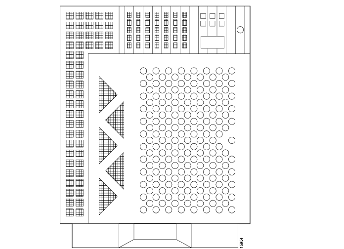
Alarm Relay Unit (ARU)

The ARU transmits critical, major, and minor alarms to the alarm center in the Network Operations Center (NOC).

Figure 11 Alarm Relay Unit
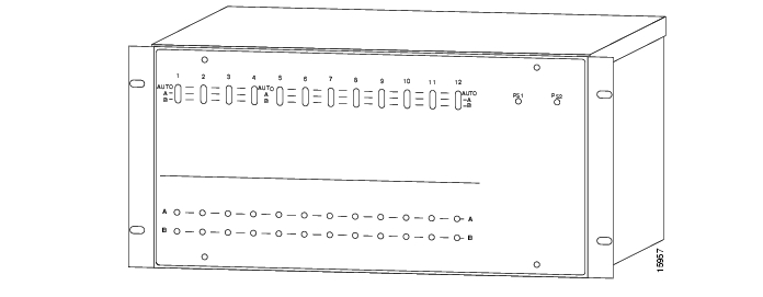
Failover Controller

The Failover controller (also sometimes referred to as an A/B switch) implements the failover procedure. The controller is only required if you have a failover configuration. If using the failover controller, you need to connect the active and standby signaling controller hosts via an Ethernet hub. The Ethernet (10 or 100 MB) hub is not supplied as a part of the signaling controller system. You can order the hub from Cisco Systems or supply your own hub. For a brief overview of the failover process, see the section " Understanding the Failover System."

Figure 12 Failover Controller

Patch Panel

The patch panel is used to connect site network E1/T1/V.35 lines to the signaling controller.

Figure 13 Patch Panel

Serial Port Expander

The serial port expander is required, in a failover configuration, to provide the additional asynchronous ports. For example, the Sun signaling controller hosts ship with two asynchronous ports built in. A typical failover configuration requires three asynchronous ports and a terminal (console) port.

The asynchronous ports are required for the following connections:

Connection to ARU

Connection to failover controller

Asynchronous heartbeat between the failover hosts

Figure 14 Serial Port Expander

Platform Specifications

The Cisco SC2200 is available in four models (as shown in ) for greater flexibility. Cisco provides complete systems integration, installation, and testing.

Table 12 Cisco SC2200 Platform Configuration Options 

Configuration
Description

Cisco SC2201

1 Sun Netra t host
DC powered
NEBS compliant host
256 MB RAM upgradable to 2 GB
Signaling link I/O cards
Alarm relay unit
7 ft rack
Systems integration
Installation and acceptance testing

Cisco SC2202

High availability failover architecture
2 Sun Netra t hosts (active & standby)
DC powered
NEBS compliant host
256 MB RAM upgradable to 2 GB
Signaling link I/O cards
Alarm relay unit
Optional second 10/100 BaseT ethernet
7 ft rack
Systems integration
Installation and acceptance testing

Cisco SC2211

1 Sun E 450 host
AC powered
256 MB RAM upgradable to 2 GB
Signaling link I/O cards
Alarm relay unit
7 ft rack
Systems integration
Installation and acceptance testing

Cisco SC2212

High availability failover architecture
2Sun E 450 hosts (active and standby)
AC powered
NEBS compliant
256 MB RAM upgradable to 2 GB
Signaling link I/O cards
Alarm relay unit
Optional second 10/100 BaseT Ethernet
7 ft rack
Systems integration
Installation and acceptance testing


Reference Documentation

For each component of the signaling controller, refer to the documentation that arrived with that particular component. For information about the signaling controller, see the following publications:

Cisco SC2200 Signaling Controller Configuration Tool Guide

Cisco SC2200 Signaling Controller Software Operations and Maintenance Guide

Release notes. Note that release notes are only available through your Cisco representative.

These publications are available online on the Cisco web site or on the Cisco Documentation CD-ROM that arrived with your system. See the section, " If You Need More Information," and " Cisco Connection Online," for details.

Network Access Servers

Cisco AS5200, Cisco AS5300, or Cisco AS5800 access servers provide the termination for the ISUP trunks (bearer channels).


Note   Your NAS will require MICA modems if your network implements two-wire continuity checks. In addition, this release of the Cisco SS7/CCS7 DAS does not support the Cisco AS5300 VoIP card.


Cisco AS5200

The Cisco AS5200 provides the following features:

Services and terminates asynchronous and digital (ISDN) calls with one stand-alone Cisco AS5200 and one phone number.

Supports two T1 or E1 PRI lines. Combines LAN, WAN and asynchronous line support in a single package.

Supports up to 60 (with E1 configuration) integrated modems.

Supports all protocols and services on the asynchronous ports.

Supports Telnet connections for dialing out from the network.

Supports IBM tunneling and conversion such as Data Link Switching (DLSw).

Offers bandwidth management and optimization and security features including data compression, IPX/SPX spooling, and packet filters.

Delivers multiprotocol security levels with authorization and accounting control.

Cisco AS5300

The Cisco AS5300, designed for medium to large service providers, offers the same features of the Cisco AS5200 and these additional features:

Terminates up to eight E1 or TI connections.

Provides backhaul serial support.

Cisco AS5800

The Cisco AS5800, Cisco's large-scale solution, offers these additional features:

Terminates up to 24 E1/T1 connections.

NEBS Level 3 and ETSI compliance. (These are North American and European telecom certifications.)

Reference Documentation

Refer to the hardware installation guides and the software configuration guides for each NAS, the Dial Solutions Configuration Guide, the Cisco IOS software configuration guide, and command reference publications for details on the NASs. These publications are available on the Documentation CD-ROM that arrived with your access server, on the World Wide Web from Cisco's home page, or you can order printed copies.

Network Element Management System Server

The Cisco Network Element Management System (NEMS) manages the signaling controller. The NEMS server is an NT server and requires a Pentium processor, 166 MHz speed, 128 MB RAM, and 2.2 GB hard drive. The workstation client accessing the NEMS server must also have a minimum 166-MHz processor, 16 MB of RAM, and a color monitor set for 1024 x 768 resolution.

The NEMS server also requires Microsoft internet server, Microsoft Access 97 (including ODBC drivers for Access), and Netscape Communicator 4.0+ software installed. Note that the front end of the configuration tool is a JAVA applet.

See the signaling controller documentation for additional information. The publications are available online on the Cisco web site or on the Cisco Documentation CD-ROM that arrived with your system. See the section, " If You Need More Information," and " Cisco Connection Online," for details.

Authentication, Authorization, and Accounting and Network Management Servers

These servers provide security and network management. See the Security Configuration Guide for details. This publication is available online on the Cisco web site or on the Cisco Documentation CD-ROM that arrived with your system. See the section, " If You Need More Information," and " Cisco Connection Online," for details.

Cisco SC3640

Use the Cisco SC3640 to provide SNMP offloading, system logging, TFTP services, and documentation services if you are using the Cisco AS5800 in your DAS. In addition, the Cisco SC3640 provides a direct connection (via the console port) to the signaling controller, NAS, AAA server, network management server, NEMS server, and backhaul router so that you can manage the devices if the network goes down.

See the Cisco 3640 System Controller Installation and Configuration Guide for details. This publication is available online on the Cisco web site or on the Cisco Documentation CD-ROM that arrived with your system. See the section, " If You Need More Information," and " Cisco Connection Online," for details.

Backhaul Router

The backhaul router provides a connection to the IP backbone to connect to the Internet. See the router documentation for additional information. These publications are available online on the Cisco web site or on the Cisco Documentation CD-ROM that arrived with your system. See the section, " If You Need More Information," and " Cisco Connection Online," for details.

Designing Your Network

Designing your network is a complex and sophisticated task beyond the scope of this document. This section describes very briefly some issues you need to consider while engineering your network, the traffic engineering assumptions you must take into consideration, some suggestions for routing control and data traffic, and how to design an IP subnetting and addressing plan. See the subsection " Reference Documentation" later in this section for some reference publications that you can use to design and engineer your network.

Network Engineering Assumptions

When engineering your network, you need to consider the following issues:

There should be no packet loss and the packets should not be received out of order between the signaling controller and the NASs. This could impact the performance of the Cisco SS7/CCS7 DAS and the call setup time might become unacceptable.

Do not enable load balancing in the control network. If you must use load balancing, then you must also enable destination-based load balancing. In this case, use Cisco Express Forwarding (CEF) if available. If you do not use CEF, load balancing could cause out-of-sequence delivery when the cache ages out.

If you are using Weighted Fair Queuing (WFQ) or any other type of queuing feature, make sure all signaling packets from the NASs to the signaling controller (and vice versa) show up in the same queues. Fancy Queuing is not recommended in the control network unless absolutely necessary.

If using dynamic routing protocols in the control network then out-of-sequence delivery could occur on a change of adjacency or topology. This should not be a normal occurrence in a stable network.

Traffic Engineering

Traffic engineering is the process of defining the call patterns for the services (modem or voice) you provide. Traffic engineering involves calculating the calls per second rate to define your call characteristics and performance statistics. Using this data, you can then calculate the number of trunks and ports required for a certain performance level, the number of voice trunks, number of agents required for a call center, how many modems should be in a modem pool, and so on.

Some of issues that must be considered while calculating the numbers for your network:

1 What are the services you are providing? Is this a mix of services, for example, modem pools, ISDN services, Voice over IP, and so on.

2 You need to research how your services are being used. For example, what is the recommended average hold time, what percentage of your services are enterprise versus Internet, what is the average number of hours per month for Internet users, how many users subscribe to your services, data transfer rate, what is the profile for the busy hour (day, day of year, call rate, and average hold time), and so on.

3 List the assumptions for the network. For example, the network will use only one IP subnet, there will be no voice services provided, and busy hour assumptions.

4 List the calculations you need to make. For example, the performance data, number of ports, number of modems, number of transactions per second, load on network elements or nodes, average use per user.

5 Determine the least-cost combination of trunks.

Routing Control and Data Traffic

When planning your network, sure the control traffic IP network is separate from the data IP network and is always the primary network for control traffic and does not carry any data. You also need to provide redundancy in the control network to protect against failures. We do not recommend using the data network because the failover network for the control traffic as control traffic is time sensitive and the load on the data network could be subject to unexpected highs.

There are two ways to route control traffic:

Static routing

Dynamic routing

Both options are discussed in the following sections.

Static Routing

and compare a simple network in two scenarios. The first scenario, , shows a network with no built-in redundancy for the control traffic. The second scenario, , shows the same system with a built-in redundancy for the control traffic.

In (the nonredundant system), the network includes three NASs and two signaling controllers (labeled SC1 and SC2 in the figure) with the following features:

NAS1 has dual Ethernet interfaces, with one interface providing access to the control traffic and the other providing access to the data network.

NAS2 and NAS3 each have only one Ethernet interface, which connects them to the data network. Because NAS3 has one spare serial interface, this interface is used to connect it to the control network via router R1. NAS2 receives its control traffic from the signaling controllers via R1 over the data IP network.

SC1 and SC2 can are be either a redundant pair or both can be primary signaling controllers.

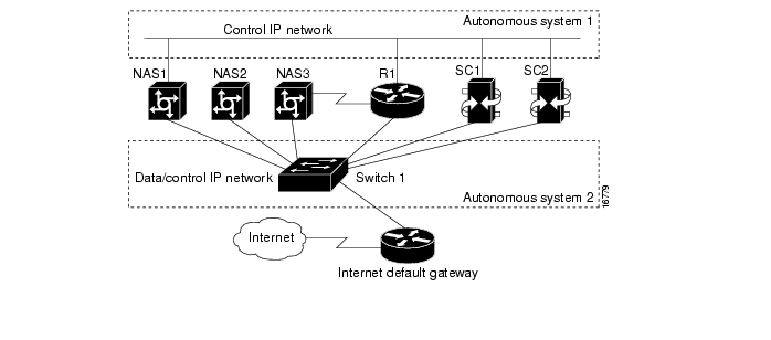
Figure 15 Simple Configuration for Control and Data IP Networks

This is how the control traffic failover works in this setup. When a NAS loses the connection over the control network, the standby link connection is initiated over the data network. To do this, we configured router R1 to statically route the signaling controller's primary IP address to the control network and its standby IP address to the data network. Thus, all data traffic is routed statically to the Internet default gateway.

This approach turns off dynamic routing in the two networks to simplify the network design. A result of statically routing control traffic over the data network is that the time-sensitive protocols of control traffic could get impacted because of the load of data traffic over the data network.

To alleviate the load of data and control traffic coming from all the NASs and signaling controllers into the same LAN, shows the use of an Ethernet switch (labeled Switch 1 in the figure) to switch data and control traffic. However, note that even in this improved setup, the control traffic will still be impacted by sharing the same interface with the data traffic within a NAS when failover occurs.

Also, NAS2 can reach the signaling controller's standby IP interface because of the limitation of number of available physical interfaces inside the router. Placing the signaling controller primary and standby interfaces on different LAN segments brings better redundancy than having both on the same LAN segment.

Figure 16 Using an Ethernet Switch to Alleviate the Impact of Heavy Data and Control Traffic

Dynamic Routing

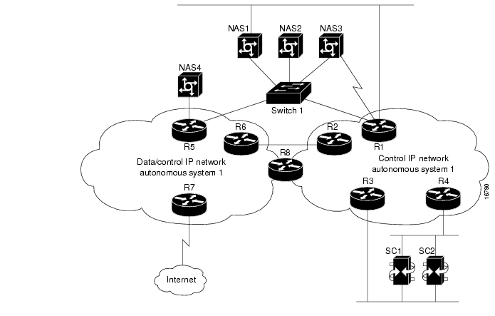
In the example in the previous section " Static Routing," it is not necessary to enable dynamic routing because the signaling controllers and the NASs are located on the same LAN segment and there is no internetworking provided by routers. But, what if dynamic routing was enabled on the NASs and the routers? In this scenario, when NAS1's IP interface on the control traffic network is down, the signaling controller's primary link is reestablished by routing the link from the IP interface on the data/control network back to control network via router R1. But, looking at , the rerouting of the primary link back to the control network is slower than taking the standby link on the data/control network because the primary link will traverse one more hop than the standby link to reach the signaling controller. Thus, for the setup in , static routing works better than dynamic routing.

Usually, dynamic routing is used in large and complicated networks especially when the control network spans across several distributed locations. shows one such network environment. This setup includes two distinct IP networks:

Control IP network is located in Autonomous system 1 and the data/control IP network is located in Autonomous system 2.

Routers R2 and R6 provide backup routing paths between the two networks.

Router R8 spans both networks.

The signaling controller primary IP and standby IP interfaces connect to different LAN segments for better redundancy. Note that this figure displays only the routers within the two networks.

Figure 17 Dynamic Routing of Control Data

In this system, Autonomous system 1 includes only control traffic while Autonomous System 2 includes both control and data traffic. To configure the networks, routing information about Autonomous system 1 is distributed to Autonomous system 2 via the edge routers connecting the two networks but routing information about Autonomous system 2 is not distributed to Autonomous system 1. This means that router R2 distributes Autonomous system 1 routing information to router R6 and vice versa. The same routing policy applies to router R8 but the difference here is that both Autonomous system 1 and Autonomous system 2 routing information resides in router R8 at the same time. (NOTE: The current Cisco IOS releases support the capabilities to selectively distribute and filter routing information going into and coming out of the router via different interfaces.)

If a NAS has only one IP interface available, it has no choice but to connect to the Autonomous system 2 network and route control traffic back to Autonomous system 1. For example, NAS4 can only connect to router R5. However, router R5 can route the control traffic to the LAN Switch 1 or routers R2 or R6.

To enable routers inside Autonomous system 2 to route control traffic back to Autonomous system 1 as soon as possible, you need to configure the routing metrics in Autonomous system 1 and Autonomous system 2 so that the shortest path between the two systems can be chosen based on the metrics. For example, one of elements of metrics is delay. All the routes inside Autonomous system 1 can be configured with much less delay than any routes inside Autonomous system 2. In a similar manner, you can configure other metrics when planning for the entire network.

Security Protection Over Control Network

You can configure Cisco access policy lists for the Autonomous system 1 edge routers connecting to Autonomous system 2 to block unwanted traffic directed to the control network.

Designing an IP Subnetting and Addressing Plan

When designing your IP subnetting and addressing plan, consider the following:

Will your IP data network and management traffic be separate?

How will your network handle voice versus data traffic? Supporting VoIP requires special considerations outside the scope of this document. Refer to the Voice Over IP Software Configuration Guide for details. This publication is available online on the Cisco web site or on the Cisco Documentation CD-ROM that arrived with your system. See the section, " If You Need More Information," and " Cisco Connection Online," for details.

Will you be using VLANs and a switch to separate the control management network from the data network?

After you have answered the above questions, you can now:


Step 1 Create an IP subnet plan for your DAS based on whether all your DAS components are located in a single subnet (see ) or two subnets (see ).

Step 2 Create the address plan based on your subnet plan.

shows an address plan for a DAS with only one subnet. The following example uses a single subnet 172.16.100.0/24.

Table 13 Address Plan for a Single Subnet

Subnet 172.16.100.0/24
Device
IP Address
Port

Backhaul router

172.16.100.1/24

Ethernet 0

Security server

172.16.100.5/24

Ethernet 0

SNMP server

172.16.100.6/24

Ethernet 0

Cisco SC3640

172.16.100.9/24

Ethernet 0

Cisco AS5X00

172.16.100.10/24

Ethernet 0

Cisco SC22XX

172.16.100.11/24

Ethernet 0


shows an address plan for a DAS with two subnets: 172.16.100.0/24 and 172.16.101.0/24.

Table 14 Address Plan for Two Subnets

Subnet 172.16.100.0/24
Device
IP Address
Port

Security server

172.16.100.5/24

Ethernet 0

SNMP server

172.16.100.6/24

Ethernet 0

Cisco SC3640

172.16.100.9/24

Ethernet 0

Cisco SC22XX

172.16.100.11/24

Ethernet 0

Backhaul router

172.16.101.1/24

Ethernet 1

Cisco AS5X00 (to Ethernet 1 on backhaul router)

172.16.101.2/24

Ethernet 1


Reference Documentation

See the following publications for detailed information:

Voice Design and Implementation Guide

Cisco Security Configuration Guide

Cisco Wide-Area Networking Configuration Guide

Cisco Internetworking Case Studies

Lewis, C. Cisco TCP/IP Routing Professional Reference. MacGraw-Hill; 1997

Ramses, M. Introduction to Teletraffic Engineering. 1985.

Boucher, J.R. Voice Teletraffic Systems Engineering. Artech House; 1988.

The Cisco publications are available online on the Cisco web site or on the Cisco Documentation CD-ROM that arrived with your system. See the section, " If You Need More Information," and " Cisco Connection Online," for details.


Tips

You can also search for the keyword erlang in the category telecommunications on the web for more information on designing your network traffic.


Preparing for Implementation of Cisco SS7/CCS7 DAS

Before you can start configuring the various components in the Cisco SS7/CCS7 DAS, you need to have information, such as IP addresses, PCs, span IDs, and so on available. This section provides tables you can fill in with the required information before configuring the DAS components.

Note that the values already entered in the tables are either required values for the signaling controller or a value you can use to avoid mismatching names where needed and matching names where not needed, for example, the IP service names on the signaling controller and NASs.

After you enter the signaling controller configuration information using configuration tool on the NEMS server, and then build and deploy the configuration, the result is a set of configuration (.dat) files that are copied to the signaling controller.


Note   Do not use spaces in for Tag and Name values in the following sections.


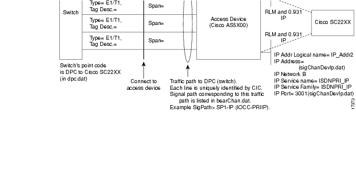
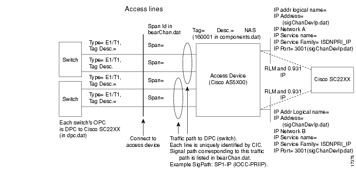
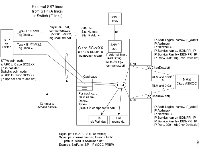
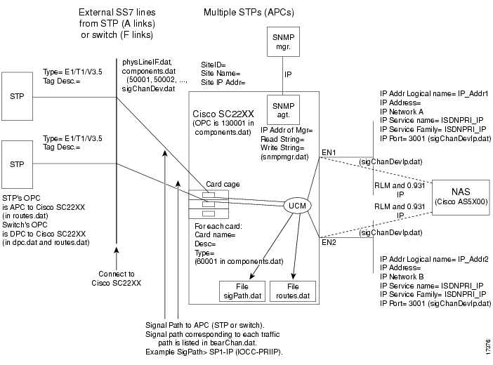
Figure 18, Figure 19, Figure 20, and Figure 21 display information you need to collect for configuration.

Figure 18 Information for Access Lines if Using a Single Switch

Figure 19 Information for Access Lines if Using Multiple Switches

Figure 20 Information for External SS7 Lines (A- or F-links) Using a Single STP or Switch

Figure 21 Information for External SS7 Lines (A- or F-links) Using Multiple STPs or Switches

SS7 and PSTN Data

Telco Switches Attached to the Signaling Controller

Table 15 Telco Switches

Telco Switch No.
Point Code1
Network Indicator
Type2

1


2


3


4


1 DPC in traffic path in signaling controller, listed in dpc.dat

2 For information only


STPs Attached to the Signaling Controller

Table 16 STPS

STP No.
Point Code1
Network Indicator

1


2


3


4


1 APC in signal path in signaling controller.


IP Data

Site Information

Table 17 General Site Information

Site Name
Location
   

Access Lines

Access lines are the lines going directly into the associated NASs.

Table 18 From Switch No. 1 (bearChan.dat)

Tag1
Type (T1|E1)
Line Framing & Coding2
Description
Span ID3
CIC Codes4


1 Referred to as AL-TAGs.

2 For example, ESF/B8ZS. You can enter a value when configuring the NAS; for the signaling controller a default value is already selected. To change the signaling controller default value, you need to manually edit the physLineIf.dat file.

3 Needed when connected to NAS. Must match IOS NFAS_INT # in Pri-group command.

4 Range, for example 1 to 24.


Table 19 From Second Switch No. 1 (if applicable) (bearChan.dat)

Tag1
Type (T1|E1)
Line Framing & Coding2
Description
Span ID3
CIC Codes4


1 Referred to as AL-TAGs.

2 For example, ESF/B8ZS. You can enter a value when configuring the NAS; for the signaling controller a default value is already selected. To change the signaling controller default value, you need to manually edit the physLineIf.dat file.

3 Needed when connected to NAS. Must match Cisco IOS NFAS_INT # in Pri-group command.

4 Range, for example 1 to 24.


Add additional access lines tables if the signaling controller and NASs are connected to more switches.

External Lines

External lines are the SS7 signaling lines connecting to the signaling controller line interface cards. The actual line interface cards accepting the SS7 lines are defined in and .

Table 20 From First STP or Switch

Tag1
Type (T1/E1/V.35)
Description
Link Code2


1 Referred to as SS7-TAGs.

2 This is the SLC for this link in its linkset.


Table 21 From Second STP or Switch

Tag1
Type (T1/E1/V.35)
Description
Link Code2


1 Referred to as SS7-TAGs.

2 This is the SLC for this link in its linkset.


Add additional SS7 line tables if the signaling controller is connected to other STPs (via A links) or switches (via F links).

NASs

These are the NASs connected directly to the T1/E1 bearer trunks from the telco switches and receiving ISDN signaling from the signaling controller over IP interfaces.

NAS No. 1

Table 22 General Information

Tag1
Type
Description
 

NAS


1 Referred to as NAS1-TAG.


Table 23 IP Interface 1 on NAS No. 1 for Network A

IP Address
IP Logical Name
IP Service Name1
IP Service Family2
IP Port3
 

NAS1_IP_14

NAS1IP_PRI

ISDNPRI_IP

3001

1 This is the logical name of the signaling protocol over IP. This name is used in the traffic path configuration below. Use value below.

2 Select from list. This is the signaling protocol over IP.

3 Default port number on Cisco AS5X00.

4 Use this value.


Table 24 IP Interface 2 on NAS No. 1 for Network B (if applicable)

IP Address
IP Logical Name
IP Service Name1
IP Service Family2
IP Port3
 

NAS1_IP_24

NAS1IP_PRI

ISDNPRI_IP

3001

1 This is the logical name of the signaling protocol over IP. This name is used in the traffic path configuration below. Use value below.

2 Select from list. This is the signaling protocol over IP.

3 Default port number on Cisco AS5X00.

4 Use this value.


NAS No. 2

Table 25 General Information

Tag1
Type
Description
 

NAS


1 Referred to as NAS1-TAG.


Table 26 IP Interface 1 on NAS No. 2 for Network A

IP Address
IP Logical Name
IP Service Name1
IP Service Family2
IP Port3
 

NAS2_IP_14

NAS2IP_PRI

ISDNPRI_IP

3001

1 Logical name of the signaling protocol over IP. Used in the traffic path configuration. Use the listed value.

2 Select from list. This is the signaling protocol over IP.

3 Default port number on Cisco AS5X00.

4 Use this value.


Table 27 IP Interface 2 on NAS No. 2 for Network B (if applicable)

IP Address
IP Logical Name
IP Service Name1
IP Service Family2
IP Port3
 

NAS2_IP_24

NAS2IP_PRI

ISDNPRI_IP

3001

1 Logical name of the signaling protocol over IP. Used in the traffic path configuration. Use the listed value.

2 Select from list. This is the signaling protocol over IP.

3 Default port number on Cisco AS5X00.

4 Use this value.


Tips

The IP service name for both IP interfaces (networks A and B) must match. This name is used in the traffic path configuration, and associates the traffic path to the IP interfaces that will provide signaling for these T1/E1 lines.

The signaling controller configuration tool uses the IP service names to distinguish the NASs during the building and deployment of the signaling controller configuration files.

Signaling Controller

This device accepts SS7 lines from the telco STPs or switches and provides ISDN Q.931 signaling over IP to the associated NASs.

Table 28 Signaling Controller Definition

ID1
Name2
Description
Access Type
IP Address3
     

NAS


1 Database name, 1 to 3 digits

2 1 to 4 characters

3 Network A


Table 29 SNMP Manager Configuration (if applicable)

Name
IP Address1
Read Community String
Write Community String

Manager0012


Public

Write


1 SNMP manager

2 Default name


Note   You cannot change the community string values shown in the table.


Table 30 Signaling Controller Card

Card Cage Name
Description
Type1
     

1 If using Sun servers, you have these options:
Netra (3 card slots for ITK/PTI cards)
Ultra 5 (3 card slots for ITK/PTI cards)
Enterprise 450 (7 card slots for ITK/PTI cards)


Table 31 Cage Slot Information

Slot Name
Card Name
Description
Type1
DTE/DCE
Clock (Int/Ext)
Data Rate

Slot_0


Slot_1


Slot_2


1 ITK:T1 or ITK:E1 ( RJ48 line interface)
PTI_V35:V35 (4 V.35 line interfaces; special 1-to-4 V.35 fan-out cable required)


Note   Add additional slots for the signaling controller card cage.


Table 32 SS7 Lines Connected to Line Interfaces

Slot/LIF1
SS7 Line Tag2


1 For example, Slot_0/LIF_0

2 From or


Note   Created automatically from IP address given in signaling controller configuration above.


Table 33 IP Interface 1 on Signaling Controller for Network A

IP Address1
IP Logical Name
IP Service Name2
IP Service Family3
IP Port4
 

IP_Addr1

ISDNPRI

ISDNPRI_IP

3001

1 Filled in from .

2 This is the logical name of the signaling protocol over IP. This name is used in the signal path configuration in .

3 This is the signaling protocol over IP.

4 Default port number on Cisco ASX00.


Table 34 IP Interface 2 on Signaling Controller for Network B

IP Address1
IP Logical Name
IP Service Name2
IP Service Family3
IP Port4
 

IP_Addr2

ISDNPRI

ISDNPRI_IP

3001

1 Filled in from .

2 This is the logical name of the signaling protocol over IP. This name is used in the signal path configuration in .

3 This is the signaling protocol over IP.

4 Default port number on Cisco AS5X00.


Traffic Paths

Traffic paths define the T1/E1 lines from a switch with a unique SS7 DPC to the signaling controller and attached to one of the NASs associated with this signaling controller. This is how traffic paths are calcuated:

1 DPC + 1 NAS = 1 traffic path

2 DPC + 1 NAS = 2 traffic paths

1 DPC + 2 NAS = 2 traffic paths

2 DPC + 2 NASs = 1 traffic path

Table 35 Traffic Path No. 1

Path name


Description


Tag


Protocol Family


Variant


Usage

Access

DPC/Net. ID1


Access Device2


Access IP Service3


1 Switch PC.

2 NAS attached to the T1/E1 lines from the DPC.

3 Must match the IP service name selected for the IP interfaces for the NAS.


Table 36 Access Lines in Traffic Path No. 1

AL-Tag1
Bearer Channels2
CIC Codes3


1 From Access lines section.

2 DS0s from each T1/E1 that are bearer channels; e.g., 1 to 24 for T1.

3 Corresponding to each bearer channel. The current release of the signaling controller supports 4096 CICs (0 to 4095).


Table 37 Traffic Path No. 2

Pathname


Description


Tag


Protocol family


Variant


Usage

Access

DPC/Net. ID1


Access Device2


Access IP Service3


1 Switch's PC.

2 NAS attached to the T1/E1 lines from the DPC.

3 Must match the IP service name selected for the IP interfaces for the NAS.


Table 38 Access Lines in Traffic Path No. 2

AL-Tag1
Bearer Channels2
CIC Codes3


1 From the tables in the section " Access Lines."

2 DS0s from each bearer channel T1/E1; e.g., 1 to 24 for T1.

3 Corresponding to each bearer channel. The current release of the signaling controller supports 4096 CICs (0 to 4095).


Signal Paths

Signal paths define the SS7 lines from an STP or switch connected to the Cisco SC22XX.


Note   One signal path for each STP or switch providing SS7 lines to the Cisco SC22XX is required. One signal path can contain more than one SS7 line from a single STP or switch. Each SS7 line from the same STP or switch is in the same linkset and MUST have a unique link code.


Table 39 Signal Path No. 1 

Tag
Information

Description


Protocol family


Variant


Usage

Access

OPC/Net. ID1


Priority


Load Sharing (Y/N)


APC2


Destinations: Traffic Path Tags3


1 Own PC.

2 Adjacent PC; STP or switch's PC.

3 Traffic paths represented by this signal path; refer to , , , and .


Table 40 Channels (SS7 Lines) in Signal Path No. 1

SS7 Line Tag1
Timeslot2
Link Code3
Priority


1 From .

2 (DS0) of SS7 link in T1/E1 (1 to 24 for T1, 1to 31 for E1). If SS7 line is V.35, this is not applicable.

3 Values are 0 to 16 and must match the switch or STP configuration.


Table 41 Signal Path No. 2 

Tag
Information

Description


Protocol family


Variant


Usage

Access

OPC/Net. ID1


Priority


Load Sharing (Y/N)


APC2


Destinations: Traffic Path Tags3


1 Own PC.

2 Adjacent PC; STP or switch's PC.

3 Traffic Paths represented by this signal path; refer to .


Table 42 Channels (SS7 lines) in Signal Path No. 2

SS7 Line Tag1
Timeslot2
Link Code3
Priority


1 From .

2 (DS0) of SS7 link in T1/E1 (1 to 24 for T1, 1 to 31 for E1). If SS7 line is V.35, this is not applicable.

3 Values are 0 to 16 and must match the switch or STP configuration.


Table 43 RLM (Redundant Link Manager) Configuration

RLM Port Number
RLM Timer Link Down
RLM Time Cmd Ack
RLM Link UP Recovered

30001

100

10

10

1 If you do not use this value, then the service IP port value (entered in Table 23, Table 24, Table 26, and Table 27) must be a value greater than the value of the RLM port number. For example, RLM port + 1 = ISDN IP service port.


Signaling Controller Configuration Information

lists the configuration (.dat) files created by the configuration tool when configuring the signaling controller and also provides a reference to the corresponding table used to collect information and values earlier in this section.

Table 44 .dat File Information 

.dat Filename
Information (and table it comes from)

components.dat

10001 from (columns 2 and 3)
50001/2 from (columns 2 and 3)
50003/4 built automatically for each Ethernet interface on the signaling controller.
60001-x from (column 2)
6000x+1/x+2 built automatically for each Ethernet interface on the signaling controller.
8000x from .
130001 from and (row 6)
130002-x from and (row 7)
140001-x from and .
160001-x from and (column 1)
170001 from .

bearChan.dat

and contain Span IDs (column 6 in .dat file) and CIC codes (column 3 in .dat file). The PC reference in column 1 of this .dat file is resolved components.dat.

dpc.dat

contains the DPC and Network ID (columns 2 and 3 in .dat file).

physLineIf.dat

contains all of the information about the cards in columns 2 to 11 of this .dat file. The Ethernet information in this .dat file is entered automatically based on number of IP interfaces defined in and .

snmpmgr.dat

contains information on the SNMP manager included in this .dat file.

sigChanDevIP.dat

and contain the signaling controller IP interface logical names and port numbers that are shown in columns 2 and 3 in this .dat file. , , , and contain the NAS IP interface addresses and port numbers that are shown in columns 4 and 5 in this .dat file.

sigChanDev.dat

contains information about the link codes, priority, and timeslots carrying the SS7 channels, which is shown in columns 2, 3, and 7 of this .dat file. All other information in this .dat file can be referenced in components.dat.

sigPath.dat

For SS7 external lines, the information contained in this .dat file is from . For ISND PRI signaling over IP interfaces, the information contained in this .dat file is from and .

routes.dat

and contain the PC information contained directly or indirectly (that is, referenced in components.dat) in this .dat file. OPC is shown in column 5 and the APC for this route is shown in column 6 in this .dat file. References to 13000x represent the DPC for the route. References to 8000x represent the signal path name from .

properties.dat

Table 29 contains the RLM information shown at the bottom of this .dat file.


Implementing the Cisco SS7/CCS7 DAS

Sequence of Implementation

To implement your Cisco SS7/CCS7 DAS, you need to:


Step 1 Do a traffic study for your network. See the section "Traffic Engineering" for details.

Step 2 Design your network by identifying the physical configuration and components of your network. This network design should be based on assumptions that meet your network requirements. See the section "Network Engineering Assumptions" for a list of commonly used assumptions.

Step 3 Create an IP subnetting and addressing plan. See the section "Designing an IP Subnetting and Addressing Plan" for details.

Step 4 Connect the hardware. See the section "Hardware Connections" for details.

Step 5 Connect all the devices to the network. Refer to the device documentation for details.

Step 6 Install software on the devices. See the section "Installing Software" for details.

Step 7 Configure and deploy the configuration files on all the devices in this order:

(a) Configure the NASs and assign IP addresses to the NASs. See the section "Configuring the NAS" for details.

(b) Configure the NEMS server and assign an IP address to the server. See the section "Configuring the Cisco SC22XX Signaling Controller" for details.

(c) Assign an IP address to the signaling controller and then create and deploy the configuration file on the signaling controller. See the section "Configuring the Cisco SC22XX Signaling Controller" for details.

(d) Configure the backhaul router and assign and IP address to the router. Refer to the router documentation for details.

(e) Configure the Cisco SC3640, AAA server, and network management server. Refer to the appropriate documentation for details.

Step 8 Make sure all the devices can talk to each other by pinging one device from another. For example, you should be able to ping the backhaul router and the DNS server (node in the Internet cloud) from each device. You should also be able to access (using Telnet, ReflectionX, or other such software) each device from the other devices.

Hardware Connections

This section provides an overview of the recommended hardware connection sequence. For details, refer to the appropriate hardware installation guide. Make sure you have the hardware installation guides handy for all the devices you are connecting in your DAS network.


Step 1 Wire up the signaling controller in this sequence:

(a) If using dedicated DC power, connect the power supply to the signaling controller.

(b) Install the expansion slot between the signaling controller and failover box.

(c) Connect the Ethernet hub to your LAN. Note: The hub is not provided with the signaling controller.

(d) Connect a console terminal to the signaling controller hosts using an EIA/TIA-232 cable.

(e) Connect the A-links from the telco to the patch panel. Refer to the patch panel documentation for details.

(f) Connect the signaling controller to the IP network to which the NASs will be connected.

Step 2 If you have one IP network, connect the NASs to the Ethernet hub. If you have two IP networks (see ), use the NAS Ethernet port to connect each NAS to the Dial POP managment network and use the NAS Fast Ethernet port to connect each NAS to the IP data network. Refer the NAS hardware installation guides for details.

Step 3 Connect the bearer channels to the NAS using RJ-48 connections for the E1 and T1 interfaces, or an optional BNC (75 ohms) connection for the E1 interface.

Step 4 Connect the signaling controller, NASs, NEMS server, AAA server, network management server, and backhaul router to the console ports on the Cisco SC3640 using EIA/TIA RS-232 console cables.You can now telnet directly into each device in your DAS (even if the network goes down).

Installing Software

Install software on the DAS components in this sequence:

1 Cisco SC22XX signaling controller

2 NEMS server

3 Cisco NASs

4 AAA server

5 Cisco SC3640

6 Network management server

7 Backhaul router

Configuring the Cisco SC22XX Signaling Controller


Caution   
Always use the signaling controller configuration tool to create, modify, manage, and deploy your configuration files on the signaling controller. We do not recommend modifying the configuration files directly on the signaling controller.

Configuration Steps

Configuring the signaling controller includes these steps:


Step 1 Identify the E1, T1, or V.35 cards on your signaling controller and connect your lines to cards.

Step 2 Setup the SNMP manager.

Step 3 Set up the IP interface(s) and service.

Step 4 Create traffic and signal paths.

Step 5 Set up the RLM. Although the RLM resides on the NAS and is configured using Cisco IOS software, you also need to set the RLM timers in the signaling controller configuration tool.

Step 6 Build and deploy the configuration.

Reference Documentation

For detailed installation and configuration instructions, refer to:

Cisco SC2200 Signaling Controller Configuration Tool Guide

Cisco SC2200 Signaling Controller Software Operation and Maintenance Guide

Dial Plan Provisioning Guide

The publications are available online on the Cisco web site or on the Cisco Documentation CD-ROM that arrived with your system. See the section, " If You Need More Information," and " Cisco Connection Online," for details.

Configuring the NAS

This section provides a brief overview of the COT and RLM features (new features for the Cisco SS7/CCS7 DAS), lists the steps you need to take to configure the NASs in your DAS, and displays a sample configuration file.

Continuity Testing Feature

Continuity testing (COT) is a automated diagnostic procedure performed in the PSTN between switches to ensure that circuits are in service and not experiencing excessive signal loss. On a periodic basis, the switch originating the call tells the next switch though signaling to loop back the circuit, then the requesting switch sends a tone down the line and listens for it to return. The loop-back form of COT is used on 4-wire trunks. There is also a form of COT used on 2-wire trunks deployed on some Lucent 1AESS switches in the U.S. In the 2-wire case, when the originating switch sends a tone, the receiving sends a different frequency tone in response.

COT is a requirement of North American SS7 and requires that network elements test the bearer channels. Because the bearer channels bypass the signaling controller, the NASs are responsible for testing the channels. See for platform capabilities.

Table 45 COT Support

Access Server
Loop back (4 wire)
Return tone (2 wire)
Originate COT

Cisco AS5800

Yes

Yes

Yes

Cisco AS5300 w/MICA

Yes

Yes

Yes

Cisco AS5300 w/Microcom

Yes

No

No

Cisco AS5200 w/MICA

Yes

Yes

Yes

Cisco AS5200 w/Microcom

Yes

No

No


COT works as follows:

1 COT tests the bearer channels status via either loopback or tone detection and generation.

2 The signaling controller receives the COT request from the SS7 network and forwards a message to the NAS.

3 The NAS runs the test and sends an indication of success or failure of COT back to the signaling controller.

4 If the signaling controller does not receive the indication it times out the COT test and retries the test a specific number of times as per the ANSI SS7 protocol specification.

5 If all retries fail, the signaling controller takes the line out of service, sends a message to the originating switch of CIC failure, and creates an alarm on the traffic channel.

For details, see the publication Continuity Testing (COT) at this url:

http://www.cisco.com/univercd/cc/td/doc/product/access/sc/r2/ios_r2/index.htm

Redundant Link Manager Feature

The Redundant Link Manager (RLM) provides virtual link management over multiple IP networks. This allows for the transportation of Q.931 and other proprietary protocols over multiple redundant links between the signaling controller and the NASs. RLM also performs the following functions:

Opens, maintains, and closes multiple links.

Manages buffers of queued signaling messages.

Monitors active links for link failover and signaling controller failover.

The RLM goes beyond Q.921, because it allows for future use of different upper layers, and also allows the upper layers to treat multiple, redundant paths one path. Note that configuring RLM also configures COT on your NAS. Although the RLM resides on the NAS and is configured using Cisco IOS, you also need to set the RLM timers in the signaling controller configuration tool.

See the publication Redundant Link Manager Feature at this url:

http://www.cisco.com/univercd/cc/td/doc/product/access/sc/r2/ios_r2/index.htm

Understanding Cisco IOS Software Release Trains

describes the Cisco IOS software release trains.

Table 46 Cisco IOS Software Release Trains 

Release
Description

Early Field Test (EFT)

These deliveries are usually by special arrangement with specific customers to test certain features before they are added to a train.

Specials: Limited-Life Special Trains (such as, XA, XB, and NY)

Early-delivery special and custom special trains are limited-life or "one-off" releases delivered to capitalize on market or revenue opportunities in advance of regularly scheduled maintenance releases of Early Deployment releases. These Limited-Life Specials are derivatives of existing, Ongoing Special trains.

Specials: Ongoing Special Trains (such as AA, NA, and 12.0 S)

Ongoing Special trains are those deployed early, and are derived from a standard Technology Train (Early Deployment IOS mainline release (ED release) trains). Typically, special software releases are targeted toward a specific market, such as early adopter customers and/or customers requesting special features. Features from these trains are generally later committed to the Early Deployment maintenance releases, but have been seen to be committed directly to the new Mainline release.

Technology Trains (Early Deployment for Cisco IOS Mainline such as, 11.3(4) T, 12.0(1) T, or 12.0 (3) T

Technology Trains, or Early Deployment (ED) releases, are based on a major (mainline) release of Cisco IOS software. They are used to deliver new platforms and features through regularly scheduled maintenance releases.

Cisco IOS Mainline Releases (such as, 11.2, 11.3, and 12.0)

Cisco IOS Mainline releases incorporate all features released through the Technology maintenance releases delivered since the previous mainline release.


Configuration Steps

For each NAS installed in your Cisco SS7/CCS7 DAS, you need to:


Step 1 Configure the switch type to NI2 using the isdn switch-type primary-ni command. This command enables the connection between the NAS and the signaling controller. You also need to enable COT loopback support for call termination from SS7 using the isdn service cot command.

Step 2 Configure the access server for channelized T1 or E1 lines.

Step 3 Configure the D channels for modem signaling and to receive calls using the RLM-group command.

Sample Configuration Output

This is a sample configuration output from a Cisco AS5800 setup for bearer channels. Explanation of setup is included within the output in bold body text.

version 11.3
service timestamps debug uptime
service timestamps log uptime
no service password-encryption
!
hostname hegel
!
boot system slot0:c5800-p4-mz.rel2.Sep09
enable secret 5 $1$3qCJ$5/eR47qFX360VjaPEagiF.
!
shelf-id 0 router-shelf
shelf-id 1 dial-shelf
!
dial-tdm-clock priority 1 trunk-slot 0 port 0
!
modem-pool Default
pool-range 1/2/0-1/2/71
!
modem-pool sw56
!
ip host paloalto 171.71.120.19
ip host gainesville 172.24.234.14
ip host tallahassee 172.24.234.13
ip name-server 171.71.120.12
ip address-pool local
async-bootp dns-server 171.71.120.12
isdn switch-type primary-ni
!
!

In the following output, the nfas_d command sets up the D channel for the nfas group. You only need to set this for the first controller. The command nfas_init creates the SPAN ID for this controller. This ID matches the SPAN in the signaling controller configuration tool. The command nfas_group command sets up the NFAS group. You require only 1 traffic path per NFAS group.

controller T1 1/0/0
framing esf
linecode b8zs
pri-group timeslots 1-24 nfas_d primary nfas_int 0 nfas_group 0
!
controller T1 1/0/1
framing esf
linecode b8zs
pri-group timeslots 1-24 nfas_d none nfas_int 1 nfas_group 0
hold-queue 10 in

Sets up the Ethernet address on the NAS.

interface FastEthernet0/0/0
ip address 171.71.120.100 255.255.255.0
no logging event link-status
!

Sets up IP D-channel parameters for ISDN calls.

interface Serial1/0/0:23
no ip address
ip helper-address 172.24.234.14
encapsulation ppp
no logging event link-status
isdn switch-type primary-ni
isdn incoming-voice modem
isdn rlm-group 0
!

Sets up Async group parameters for Modem and data calls.

interface Group-Async0
ip unnumbered FastEthernet0/0/0
encapsulation ppp
no logging event link-status
async mode interactive
peer default ip address pool default
no cdp enable
group-range 1/2/00 1/2/71
hold-queue 10 in
!
ip local pool default 171.71.120.101
ip classless
ip route 0.0.0.0 0.0.0.0 171.71.120.6
!
!

Sets up the RLM group. You need to specify the server name and IP address. Note that you are using a failover configuration, you need to set up two servers in a single RLM group. Each nfas_group (D channel) can only have a single rlm group assigned.

rlm group 0
server gainesville
link address 172.24.234.14 source FastEthernet0/0/0 weight 1
server tallahassee
link address 172.24.234.15 source FastEthernet0/0/0 weight 1
!
!
line con 0
exec-timeout 0 0
transport input none
line aux 0
line vty 0 4
exec-timeout 0 0
password cisco
login
line 1/2/00 1/2/71
autoselect during-login
autoselect ppp

Reference Documentation

For detailed configuration instructions, refer to:

Dial Solutions Configuration Guide

Dial Solutions Command Reference Guide

Cisco AS5X00 Universal Access Server Software Configuration Guide

These publications are currently available online or on the Cisco Documentation CD-ROM. See the section, " If You Need More Information," and " Cisco Connection Online," for details.

Configuring Other Components

Refer to the documentation that shipped with a particular component for configuration information.

Getting Help

You have 24-hour support for your SS7 dial access solution via Cisco's Technical Assistance Center (TACs). There are four TACs worldwide. To initiate a case, contact the closest TAC and tell them your problem. You will be issued a case number that you can check via the phone or the web. See for a list of telephone numbers you can call.

Table 47 TAC Telephone Numbers 

Region
Telephone

Asia-Pacific

+61 2 9935 4107

Australia

1 800 805 227

China

10810, then 800 501 2306 - Mandarin
10811, then 800 501 2306 - English
800 810 8886 - in country TAC support

Europe

+32 2 778 4242

France

0590 7594

Hong Kong

800 96 5910

India

000 117 then 888 861 6453

Indonesia

001 800 61 838

Japan

0066 33 800 926
0120 086771 - in country TAC partners

Korea

00798 611 0712 - Seoul
00 911, then 888 861 5164

Malaysia

1 800 805880

New Zealand

0800 44 6237

North America

1 800 553 2447
1 408 526 7209

Philippines

1800 611 0056

Seoul

00 911 then 888 861 5164

Singapore

800 6161 356

Taiwan

0080 61 1206

Thailand

001 800 611 0754

UK

0800 960 547


Cisco TAC also offers support in several languages during business hours and English after business hours. You can send email to the e-mail addresses listed in and receive answers in the language indicated in the table.

Table 48 TAC E-mail Addresses

Language
E-mail Address

English/Spanish

tac@cisco.com

Hangul (Korean)

korea-tac@cisco.com

Hanzi (Chinese)

chinese-tac@cisco.com

Kanji (Japanese)

japan-tac@cisco.com

Thai

thai-tac@cisco.com


You can also initiate your case online via the internet at www.cisco.com. Outside these locations, contact the Cisco regional sales office nearest you, or contact your local authorized Cisco distributor.

Where to Get the Latest Version of This Guide

The hard copy of this publication is updated at major releases only and does not always contain the latest material for enhancements occurring between major releases. You are shipped separate release notes or configuration notes for spares, hardware, and software enhancements occurring between major releases.

The online copy of this guide is always up-to-date and integrates the latest enhancements to the product. You can access the current online copy of this guide on the World Wide Web at http://www.cisco.com, http://www-china.cisco.com, or http://www-europe.cisco.com.

Signaling Controller Documentation Roadmap

Once you have read this publication, we recommend continuing with the following publications. (Note that each section in this publication also provides a list of reference documentation that you can refer to while reading a particular section.)

1 Cisco SC2200 Signaling Controller Configuration Tool Guide (78-5943-01)—hardcopy ships with the signaling controller but the most current version is available on the Cisco web site.

2 Cisco SC2200 Signaling Controller Dial Plan Provisioning Guide (78-5942-01)—available on the Cisco web site.

3 Cisco SC2200 Signaling Controller Software Operations and Maintenance Guide (78-5941-01)—available on the Cisco web site.

4 Release Notes—available from your Cisco representative.

Hotlinks to Online Documentation

The Web provides the following documentation related to the Cisco SS7 dial access solution:

Cisco SC2200 Signaling Contoller Documentation:

http://www.cisco.com/univercd/cc/td/doc/product/access/sc/r2/index.htm

Cisco Dial Solutions Quick Start Guide:

http://www.cisco.com/univercd/cc/td/doc/product/software/ios120/12supdoc/dsqcg3/index.htm

Cisco Dial Solutions Quick Configuration Guide:

http://www.cisco.com/univercd/cc/td/doc/product/software/ios113ed/113ed_cr/dial_c/index.htm

Cisco Dial Solutions Command Reference:

http://www.cisco.com/univercd/cc/td/doc/product/software/ios113ed/113ed_cr/dial_r/index.htm

Cisco Network Access Server configuration:

http://www.cisco.com/univercd/cc/td/doc/product/access/acs_serv/5300/cfios/cot_rel2.htm

http://www.cisco.com/univercd/cc/td/doc/product/access/acs_serv/5300/cfios/isdnrel2.htm

http://www.cisco.com/univercd/cc/td/doc/product/access/acs_serv/5300/cfios/rlm_rel2.htm

Cisco access server documentation:

http://www.cisco.com/univercd/cc/td/doc/product/access/acs_serv/index.htm

Cisco AccessPath system documentation:

http://www.cisco.com/univercd/cc/td/doc/product/access/ap/index.htm

Cisco Access Server Release Notes:

http://www.cisco.com/univercd/cc/td/doc/product/software/ios113ed/ios113p/5300as/52c53c34.htm

http://www.cisco.com/univercd/cc/td/doc/product/software/ios113ed/ios113p/5800acs/rn5800.htm

SS7 tutorial:

http://www.iec.org/

Click Training, Web ProForum Tutorials, Communications Networks, and then scroll down the list and click Signaling System #7 (SS7).


If You Need More Information

The Cisco IOS software running on your router contains extensive features and functionality. The effective use of many of these features is easier if you have more information. For additional information on configuring and maintaining a signaling controller, the following documentation resources are available:

Cisco Documentation CD-ROM

Cisco documentation and additional literature are available on a CD-ROM, which ships with your product. The Documentation CD-ROM, a member of the Cisco Connection Family, is updated monthly; therefore, it might be more up to date than printed documentation. To order additional copies of the Documentation CD-ROM, contact your local sales representative or call customer service. The CD-ROM is available as a single item or as an annual subscription. You can also access Cisco documentation on the World Wide Web at http://www.cisco.com, http://www-china.cisco.com, or http://www-europe.cisco.com.

If you are reading Cisco product documentation on the World Wide Web, you can submit comments electronically. Click Feedback on the toolbar and select Documentation. After you complete the form, click Submit to send it to Cisco. We appreciate your comments.


Note   You can access Cisco IOS software configuration documentation on the World Wide Web at http://www.cisco.com, http://www-china.cisco.com, or http://www-europe.cisco.com


For Cisco IOS software configuration information, refer to the modular configuration and modular command reference publications in the Cisco IOS software configuration documentation set that corresponds to the software release installed on your Cisco hardware.

To obtain general information about documentation, refer to the section " Cisco Connection Online," or call customer service at 800 553-6387 or 408 526-7208. Customer service hours are 5:00 a.m. to 6:00 p.m. Pacific time, Monday through Friday (excluding Cisco-observed holidays). You can also send e-mail to cs-rep@cisco.com, or you can refer to the Cisco Information Packet that shipped with your router.

Cisco Connection Online

Cisco Connection Online (CCO) is Cisco Systems' primary, real-time support channel. Maintenance customers and partners can self-register on CCO to obtain additional information and services.

Available 24 hours a day, 7 days a week, CCO provides a wealth of standard and value-added services to Cisco's customers and business partners. CCO services include product information, product documentation, software updates, release notes, technical tips, the Bug Navigator, configuration notes, brochures, descriptions of service offerings, and download access to public and authorized files.

CCO serves a wide variety of users through two interfaces that are updated and enhanced simultaneously: a character-based version and a multimedia version that resides on the World Wide Web (WWW). The character-based CCO supports Zmodem, Kermit, Xmodem, FTP, and Internet e-mail, and it is excellent for quick access to information over lower bandwidths. The WWW version of CCO provides richly formatted documents with photographs, figures, graphics, and video, as well as hyperlinks to related information.

You can access CCO in the following ways:

WWW:  http://www.cisco.com

WWW:  http://www-europe.cisco.com

WWW:  http://www-china.cisco.com

Telnet:  cco.cisco.com

Modem:  From North America, 408 526-8070; from Europe, 33 1 64 46 40 82. Use the following terminal settings: VT100 emulation; databits: 8; parity: none; stop bits: 1; and connection rates up to 28.8 kbps.

For a copy of CCO's Frequently Asked Questions (FAQ), contact cco-help@cisco.com. For additional information, contact cco-team@cisco.com.


Note   If you are a network administrator and need personal technical assistance with a Cisco product that is under warranty or covered by a maintenance contract, contact Cisco's Technical Assistance Center (TAC) at 800 553-2447, 408 526-7209, or tac@cisco.com. To obtain general information about Cisco Systems, Cisco products, or upgrades, contact 800 553-6387, 408 526-7208, or cs-rep@cisco.com.


Documentation CD-ROM

Cisco documentation and additional literature are available in a CD-ROM package, which ships with your product. The Documentation CD-ROM, a member of the Cisco Connection Family, is updated monthly. Therefore, it might be more current than printed documentation. To order additional copies of the Documentation CD-ROM, contact your local sales representative or call customer service. The CD-ROM package is available as a single package or as an annual subscription. You can also access Cisco documentation on the World Wide Web at http://www.cisco.com, http://www-china.cisco.com, or http://www-europe.cisco.com.

If you are reading Cisco product documentation on the World Wide Web, you can submit comments electronically. Click Feedback in the toolbar and select Documentation. After you complete the form, click Submit to send it to Cisco. We appreciate your comments.

78-6011-02


hometocprevnextglossaryfeedbacksearchhelp

Posted: Fri Aug 3 16:36:15 PDT 2007
All contents are Copyright © 1992--2007 Cisco Systems, Inc. All rights reserved.
Important Notices and Privacy Statement.