|
|

This document describes how to install an adapter plate in Cisco 3640 routers for use with the Cisco Redundant Power System (RPS). The Cisco RPS provides power system redundancy to external devices (such as routers, switches, or hubs). The system includes two fully redundant AC input power modules and four DC output power modules for connection to external devices. The Cisco RPS supports quasi-redundant and fully redundant power source configurations. To use the Cisco RPS with Cisco 3640 routers, you must remove the existing power supply and replace it with a Cisco RPS adapter plate.
This document includes the following sections:
Follow these guidelines to ensure general safety:
Safety warnings appear throughout this publication in procedures that, if performed incorrectly, may harm you. A warning symbol precedes each safety warning.
Warning This warning symbol means danger. You are in a situation that could cause bodily injury. Before you work on any equipment, be aware of the hazards involved with electrical circuitry and be familiar with standard practices for preventing accidents. To see translations of the warnings that appear in this publication, refer to the Regulatory Compliance and Safety Information document that accompanied this device.
Waarschuwing Dit waarschuwingssymbool betekent gevaar. U verkeert in een situatie die lichamelijk letsel kan veroorzaken. Voordat u aan enige apparatuur gaat werken, dient u zich bewust te zijn van de bij elektrische schakelingen betrokken risico's en dient u op de hoogte te zijn van standaard maatregelen om ongelukken te voorkomen. Voor vertalingen van de waarschuwingen die in deze publicatie verschijnen, kunt u het document Regulatory Compliance and Safety Information (Informatie over naleving van veiligheids- en andere voorschriften) raadplegen dat bij dit toestel is ingesloten.
Varoitus Tämä varoitusmerkki merkitsee vaaraa. Olet tilanteessa, joka voi johtaa ruumiinvammaan. Ennen kuin työskentelet minkään laitteiston parissa, ota selvää sähkökytkentöihin liittyvistä vaaroista ja tavanomaisista onnettomuuksien ehkäisykeinoista. Tässä julkaisussa esiintyvien varoitusten käännökset löydät laitteen mukana olevasta Regulatory Compliance and Safety Information -kirjasesta (määräysten noudattaminen ja tietoa turvallisuudesta).
Attention Ce symbole d'avertissement indique un danger. Vous vous trouvez dans une situation pouvant causer des blessures ou des dommages corporels. Avant de travailler sur un équipement, soyez conscient des dangers posés par les circuits électriques et familiarisez-vous avec les procédures couramment utilisées pour éviter les accidents. Pour prendre connaissance des traductions d'avertissements figurant dans cette publication, consultez le document Regulatory Compliance and Safety Information (Conformité aux règlements et consignes de sécurité) qui accompagne cet appareil.
Warnung Dieses Warnsymbol bedeutet Gefahr. Sie befinden sich in einer Situation, die zu einer Körperverletzung führen könnte. Bevor Sie mit der Arbeit an irgendeinem Gerät beginnen, seien Sie sich der mit elektrischen Stromkreisen verbundenen Gefahren und der Standardpraktiken zur Vermeidung von Unfällen bewußt. Übersetzungen der in dieser Veröffentlichung enthaltenen Warnhinweise finden Sie im Dokument Regulatory Compliance and Safety Information (Informationen zu behördlichen Vorschriften und Sicherheit), das zusammen mit diesem Gerät geliefert wurde.
Avvertenza Questo simbolo di avvertenza indica un pericolo. La situazione potrebbe causare infortuni alle persone. Prima di lavorare su qualsiasi apparecchiatura, occorre conoscere i pericoli relativi ai circuiti elettrici ed essere al corrente delle pratiche standard per la prevenzione di incidenti. La traduzione delle avvertenze riportate in questa pubblicazione si trova nel documento Regulatory Compliance and Safety Information (Conformità alle norme e informazioni sulla sicurezza) che accompagna questo dispositivo.
Advarsel Dette varselsymbolet betyr fare. Du befinner deg i en situasjon som kan føre til personskade. Før du utfører arbeid på utstyr, må du vare oppmerksom på de faremomentene som elektriske kretser innebærer, samt gjøre deg kjent med vanlig praksis når det gjelder å unngå ulykker. Hvis du vil se oversettelser av de advarslene som finnes i denne publikasjonen, kan du se i dokumentet Regulatory Compliance and Safety Information (Overholdelse av forskrifter og sikkerhetsinformasjon) som ble levert med denne enheten.
Aviso Este símbolo de aviso indica perigo. Encontra-se numa situação que lhe poderá causar danos físicos. Antes de começar a trabalhar com qualquer equipamento, familiarize-se com os perigos relacionados com circuitos eléctricos, e com quaisquer práticas comuns que possam prevenir possíveis acidentes. Para ver as traduções dos avisos que constam desta publicação, consulte o documento Regulatory Compliance and Safety Information (Informação de Segurança e Disposições Reguladoras) que acompanha este dispositivo.
¡Advertencia! Este símbolo de aviso significa peligro. Existe riesgo para su integridad física. Antes de manipular cualquier equipo, considerar los riesgos que entraña la corriente eléctrica y familiarizarse con los procedimientos estándar de prevención de accidentes. Para ver una traducción de las advertencias que aparecen en esta publicación, consultar el documento titulado Regulatory Compliance and Safety Information (Información sobre seguridad y conformidad con las disposiciones reglamentarias) que se acompaña con este dispositivo.
Varning! Denna varningssymbol signalerar fara. Du befinner dig i en situation som kan leda till personskada. Innan du utför arbete på någon utrustning måste du vara medveten om farorna med elkretsar och känna till vanligt förfarande för att förebygga skador. Se förklaringar av de varningar som förkommer i denna publikation i dokumentet Regulatory Compliance and Safety Information (Efterrättelse av föreskrifter och säkerhetsinformation), vilket medföljer denna anordning.
Follow these guidelines when working on equipment powered by electricity:

Electrostatic discharge (ESD) can damage equipment and impair electrical circuitry. It occurs when electronic printed circuit cards are improperly handled and can result in complete or intermittent failures. Always follow ESD prevention procedures when removing and replacing cards. Ensure that the chassis is electrically connected to earth ground. Wear an ESD-preventive wrist strap, ensuring that it makes good skin contact. Connect the clip to an unpainted surface of the chassis frame to safely channel unwanted ESD voltages to ground. To properly guard against ESD damage and shocks, the wrist strap and cord must operate effectively. If no wrist strap is available, ground yourself by touching the metal part of the chassis.
This kit includes the following items:
To install the Cisco RPS Adapter Plate, you will also need the following tools and equipment (which are not included):
To install the Cisco RPS adapter plate in Cisco 3640 routers, you need to perform the following procedures, which are described in this section:
You must remove the chassis cover to access the internal power supply.
Take these steps to remove the chassis cover:
Step 2 Attach an ESD-preventive wrist strap.
Step 3 Disconnect all network interface cables from the rear panel of the router.
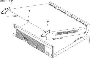
Step 4 Place the router so that the front panel is facing you. Remove the three screws located on top of the cover near the front edge, as shown in Figure 2.
Step 5 Lift the front edge of the cover until it clears the front of the chassis, as shown in Figure 2.
Step 6 Pull the cover toward you until the metal tabs on the rear edge separate from the chassis bottom, as shown in Figure 2.
Step 7 Lift the cover until it is free from the chassis and then set it aside.
This section describes how to remove the internal power supply. Although the AC power supply is shown in the illustrations that follow, the procedure is the same for removing both the AC and DC power supplies.
Take these steps to remove the power supply:
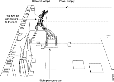
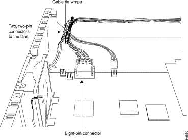
Step 2 Locate the two small two-pin connectors used to power the fans. Grasp the two halves of each connector firmly and pull them apart. (See Figure 4.)
Note If cable tie-wraps on the harness interfere with removing the connectors, cut the tie-wraps, being careful not to cut the power supply wires.
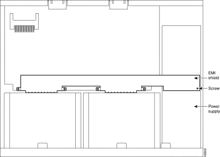
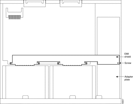
Step 3 If your Cisco 3640 router has an EMI shield as shown in Figure 5, remove the screw that secures the EMI shield to the power supply. Retain the screw for later use.
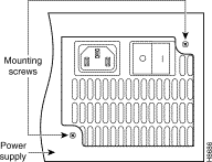
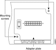
Step 4 Remove the two mounting screws that secure the power supply to the chassis and set them aside. (See Figure 6.)
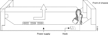
Step 5 Slide the power supply slightly forward in the chassis. This disengages the built-in hook that helps secure the power supply to the chassis. (See Figure 7.)
Step 6 Lift the power supply out of the chassis.
Take these steps to install the adapter plate:
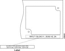
Step 2 Attach the DC power rating label over the ratings on the rear panel of the router. (See Figure 9.)
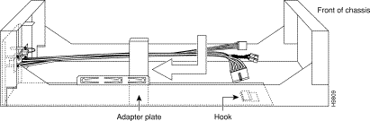
Step 3 Align the Cisco RPS Adapter Plate with the chassis cutout for the power supply and the built-in hook. Then slide the adapter plate toward you, making sure that the built-in hook engages. (See Figure 10.)
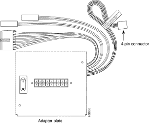
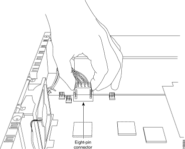
Step 4 Connect the eight-pin connector to the system board. The power connector is keyed so that it cannot be connected to the system board incorrectly. (See Figure 11.)
Step 5 Reconnect the two small two-pin connectors used to power the fans. (See Figure 11.)
Step 6 Connect the 4-pin environmental status connector only if your router, with the connector connected, has been upgraded to the correct level of IOS. Using any other level of Cisco IOS software can cause the router to crash. Version 11.1(12)AA or later is compatible, but will not show status from the RPS. Version 11.2(7)P or later will provide RPS status information to the network.
Step 7 Install the screws that were removed from the power supply into the screw holes. (See Figure 12.)
Step 8 If you removed the screw from the EMI shield in Step 3, reinstall the screw to secure the EMI shield to the adapter plate. (See Figure 13.)
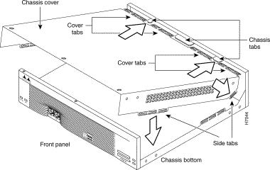
Follow these steps to replace the cover:
Step 2 Hold the cover so the tabs at the rear of the cover are aligned with the chassis bottom, as shown in Figure 14.
Step 3 Push the cover toward the rear, making sure that the cover tabs fit under the chassis back panel, and the back panel tabs fit under the top cover.
Step 4 Lower the front of the cover onto the chassis, making sure that the side tabs on the cover fit inside the chassis side panels, and the chassis tabs fit under the cover side panels.
Step 5 Secure the cover with the three screws you set aside earlier.
Step 6 Reinstall the chassis on a rack, wall, or desktop.
Step 7 Reconnect all cables.
Step 8 Remove your ESD-preventive wrist strap.
Step 9 Power ON the router.
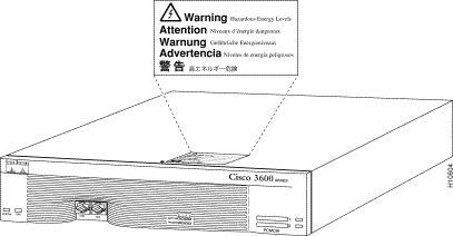
Use the following step to attach the warning label to the router:
This concludes the procedure for installing the Cisco RPS adapter plate in Cisco 3640 routers. If you need assistance, see the section "Cisco Connection Online."
Cisco Connection Online (CCO) is Cisco Systems' primary, real-time support channel. Maintenance customers and partners can self-register on CCO to obtain additional information and services.
Available 24 hours a day, 7 days a week, CCO provides a wealth of standard and value-added services to Cisco's customers and business partners. CCO services include product information, product documentation, software updates, release notes, technical tips, the Bug Navigator, configuration notes, brochures, descriptions of service offerings, and download access to public and authorized files.
CCO serves a wide variety of users through two interfaces that are updated and enhanced simultaneously: a character-based version and a multimedia version that resides on the World Wide Web (WWW). The character-based CCO supports Zmodem, Kermit, Xmodem, FTP, and Internet e-mail, and it is excellent for quick access to information over lower bandwidths. The WWW version of CCO provides richly formatted documents with photographs, figures, graphics, and video, as well as hyperlinks to related information.
You can access CCO in the following ways:
For a copy of CCO's Frequently Asked Questions (FAQ), contact cco-help@cisco.com. For additional information, contact cco-team@cisco.com.
Note If you are a network administrator and need personal technical assistance with a Cisco product that is under warranty or covered by a maintenance contract, contact Cisco's Technical Assistance Center (TAC) at 800 553-2447, 408 526-7209, or tac@cisco.com. To obtain general information about Cisco Systems, Cisco products, or upgrades, contact 800 553-6387, 408 526-7208, or cs-rep@cisco.com.
![]()
![]()
![]()
![]()
![]()
![]()
![]()
![]()
Posted: Tue Jan 21 04:34:22 PST 2003
All contents are Copyright © 1992--2002 Cisco Systems, Inc. All rights reserved.
Important Notices and Privacy Statement.