|
|

Table Of Contents
Roles and the Associations of Wireless Devices
Wireless Device Network Configuration Examples
World Mode (2.4 GHz Radio Only)
Roles and the Associations of Wireless Devices
Revised: Month day, year, OL-11494-02Introduction
This document describes the roles Cisco wireless devices can be assigned and how the role of a device affects its ability to associate or not associate with other wireless devices.
station-role Command
To change the role of a wireless Cisco device, use the station-role command. For example, the following command sets the wireless device in access point mode (the default mode of most Cisco wireless devices):
wd(config-in)#station-role root access-pointIn this mode, the device accepts associations and communicates with a non-root bridge without wireless clients, workgroup bridge, and infrastructure clients. When designing or operating a wireless LAN, the hardware components capacity to form an association with other elements of the network must be considered. In Table 1, if the two components can form an association, there is an X where the selected column and row intersect. A blank space indicates an inability to associate.
Wireless Device Network Configuration Examples
This section describes the station roles a Cisco wireless network device can serve in common wireless network configurations.
Access Point Mode
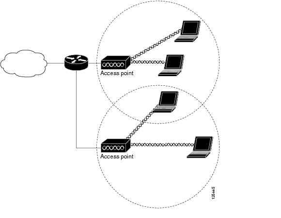
In the access point mode the router accepts associations from wireless clients and non-root devices, such as a non-root bridge. If the access point provides its clients a connection to a wired network through a wired connection it is said to be a root access point. A device in root mode accepts associations with non-root devices, such as a non-root bridge.
Figure 1 shows a typical scenario where an access point connects wireless clients to wireless and wired networks.
Figure 1 Root Access Point Mode
Use the access point command, so the wireless device accepts associations with clients and non-root devices. For example:
wd(config)#interface dot11radio interfacenumberwd(config-in)#station-role root access-pointBridge Mode
Wireless bridges provide higher data rates and superior throughput for data-intensive and line of sight applications. High-speed links between the wireless bridges deliver throughput that is many times faster than the E1/T1 lines for a fraction of the cost. In this way, wireless bridges eliminate the need for expensive leased lines and fiber-optic cables.
The wireless bridge can link LANs either through the wired interface or through the wireless interface. Wireless bridges can be configured for point-to-point and point-to-multipoint applications.
The Cisco° Metropolitan Mobile Networks (MMN) access layer is created by wireless outdoor access points and associated clients. A wireless bridge connects and passes packets between multiple network segments that use the same communications protocol, such as 802.11. Wireless bridges operate at the data link layer (Layer 2). In general, a bridge filters and forwards an incoming frame based on the MAC address of that frame-this function is the same whether it is a wireless or a wired bridge.
When two or more bridges in a Cisco MMN are used, one bridge must be defined as the root bridge. Cisco wireless bridges default to operation in root bridge mode. In any bridge domain (group of connected bridges) there should exist only one root bridge. Other bridges must be configured to operate in non-root mode. At time of activation, non-root bridges initiate a link to the root bridge; all bridges can subsequently transmit data. Clients can only associate to a non-root bridge when that bridge has a connection to a root bridge. If the connection to a root bridge is severed, all client associations to the non-root bridge will be terminated.
A workgroup bridge links wired devices to the network through its association with a wireless root device, either a root access point or a root bridge.
Additional information can be found in the Cisco Metropolitan Mobile Networks 802.11 RF Design and Deployment white paper at:
http://www.cisco.com/en/US/netsol/ns473/networking_solutions_white_paper0900aecd801016cf.shtml
The station-role root bridge mode accepts associations with non-root bridge devices and can be set to accept wireless clients. For example:
wd(config)#interface dot11radio interfacenumberwd(config-in)#station-role root bridge wireless-clientsThe root parameter specifies that the bridge operates as a root bridge to which non-root bridges can associate. The non-root parameter specifies that the router operates as a non-root bridge and must associate to a root bridge.
The wireless-clients parameter allows association with a root bridge and wireless clients.
A wireless device in bridge mode can be set to automatically select a root or a non-root role. For example:
wd(config)#interface dot11radio interfacenumberwd(config-in)#station-role install automaticIf the install parameter is set, the bridge listens for another bridge. If it does not recognize another bridge, that bridge becomes a root bridge. If it recognizes another bridge, it becomes a non-root bridge associated to the discovered bridge. If 2 or more wireless bridges are brought up at the same time and the install parameter is set, the bridge with the lowest MAC address is identified as the root bridge.
Point-to-Point Bridging
In a point-to-point bridging configuration, a non-root bridge associates to a root bridge. Wireless bridges can be deployed to establish a direct link between two sites. The network traffic between the sites is bridged, as if it were one network. In this configuration, the bridges emulate a wired point-to-point link. Point-to-point bridges can be used to link a hot spot to the distribution/aggregation devices in a network when a wireless connection is more feasible than a wired link.
Point-to-Point Bridging Without Wireless Clients
Figure 2 shows bridges in a point-to-point configuration. In this scenario, the bridges are deployed with high-gain antennas and without wireless clients to bridge long distance and maintain high-bandwidth availability.
Figure 2 Point-to-Point Bridges Without Clients
Point-to-Point Bridging With Wireless Clients
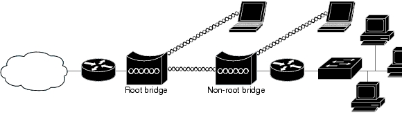
Figure 3 shows bridges with wireless clients in a point-to-point configuration. In this scenario, the non-root bridge are deployed with wireless clients to bridge through the root bridge to the Internet cloud. If the range is short, the bridges can support wireless clients and maintain high-bandwidth availability.
Figure 3 Root Bridge with Wireless Clients and Non-root Bridges with a Wireless Client
Point-to-Multipoint Bridging
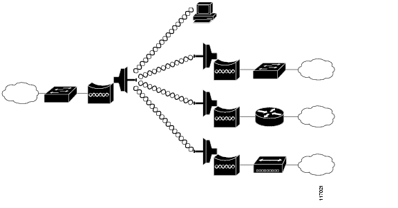
In a point-to-multipoint bridge configuration, two or more non-root bridges associate to a root bridge. Up to 17 non-root bridges can associate to a root bridge, but the non-root bridges must share the available bandwidth.
Using point-to-multipoint connection, multiple remote sites such as buildings can be linked together into a single logical network. In a point-to-multipoint architecture, these remote sites are linked to a single root bridge at a centralized site, and share the available bandwidth over the wireless link. This lowers the overall infrastructure cost per site, but might also lead to lower average throughput. Point-to-multipoint links might require additional design efforts such as traffic and capacity planning.
The root bridge acts as the master in the network relationship between the bridges and is usually in the logical center of the topology. In a point-to-point or point-to-multipoint network, you could use any of the available 802.11 b/g channels. However, if there is more than one cell in a point to multipoint network, non-overlapping channels must be used.
Figure 4 shows bridges in a point-to-multipoint configuration.
Figure 4 Point-to-Multipoint Bridge Configuration
Redundant Bridging
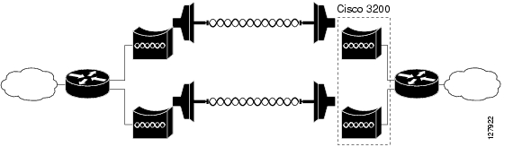
Two pairs of bridges can be deployed to add redundancy or load balancing to a bridge link. The bridges must use non-adjacent, non-overlapping radio channels to prevent interference, and they must use Spanning Tree Protocol (STP) to prevent loops. (STP is disabled by default.)
Figure 5 shows two pairs of bridges in a redundant configuration.
Figure 5 Redundant Bridge Configuration
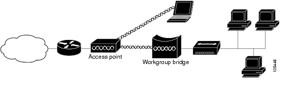
Workgroup Bridge Mode
In workgroup bridge mode, the workgroup bridge associates to an access point, or bridge as a client and provides a wireless network connection for up to eight Ethernet-enabled devices connected to its Ethernet port. It informs the associated root device of the attached wired clients using IAPP messaging. The workgroup bridge does not accept wireless client associations.
A workgroup bridge:
•
Associates to the following devices:
–
–
•
•
•
In addition, you can configure the wireless device to support the following workgroup bridge features:
•
•
To support continued operation during inter-country travel (such as airplane travel from New York to London), the workgroup bridge must perform a passive scan. In this configuration, the workgroup bridge associates to the root device, and it obtains the country-specific list of frequency and output power levels through passive scan.
To support this operational change, add the roaming keyword to the world-mode command. This option instructs the workgroup bridge that it must always passively scanning.
The workgroup bridge uses the 802.11d option for world mode. The wireless device tries to receive information about the country-specific list of frequency and output power levels through the 802.11d Information Element.
Note
•
For example, to provide wireless connectivity for a group of network printers, connect the printers to a hub or to a switch, connect the hub or switch to the Ethernet port of the workgroup bridge. The workgroup bridge transfers data through its association with an access point or bridge on the network.
Figure 6 shows a typical scenario where the device functions as a workgroup bridge.
Figure 6 Workgroup Bridge Mode
To enable the router in workgroup-bridge mode:
wd(config)#interface dot11radio interfacenumberwd(config-in)#station-role workgroup-bridgeThe device to which a workgroup bridge associates can treat the workgroup bridge as an infrastructure device or as a simple client device.
For increased reliability, set the infrastructure-client parameter on the access point or bridge to treat the workgroup bridge as an infrastructure device. When a workgroup bridge is treated as an infrastructure device, the access point reliably delivers multicast packets, which include Address Resolution Protocol (ARP) packets to the workgroup bridge.
If an access point or bridge is configured to treat a workgroup bridge as a client device, more workgroup bridges are allowed to associate to the same access point or to associate with use of a service set identifier (SSID) that is not an infrastructure SSID.
The performance cost of reliable multicast delivery—in which the duplication of each multicast packet is sent to each workgroup bridge—limits the number of infrastructure devices (including workgroup bridges) that can associate to an access point or bridge. To increase the number of workgroup bridges that can associate to the access point beyond 20, the access point must reduce the delivery reliability of multicast packets to the workgroup bridges. With reduced reliability, the access point cannot confirm that multicast packets reached the intended workgroup bridge. The workgroup bridges at the edge of the access point coverage area might lose IP connectivity.
Note
Universal Workgroup Bridge (2.4-GHz Cisco 3201 WMIC Only)
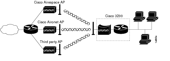
A universal workgroup bridge to provide interoperability with non-Cisco client devices that are compatible with the wireless standards.
Figure 7 shows a typical scenario in which the wireless device functions as a universal workgroup bridge.
Figure 7 Universal Workgroup Bridge Mode
The wireless device configured in universal workgroup-bridge mode supports the universal interoperability and roaming options. For example:
wd(config)#interface dot11radio interfacenumberwd(config-in)#station-role workgroup-bridge universal addressaddress is the MAC address of the router interface on the wireless and mobile router and is required to associate with Cisco and non-Cisco root devices.
Universal Workgroup Bridge Considerations
The following should be considered if configuring a wireless device as a universal workgroup bridge:
•
•
•
•
•
•
•
•
Table 2 lists the features that are supported by CCX versions:
Table 2 CCX Version Feature Support
WPA1
X
X
X
X
X
X
IEEE 802.11i - WPA2
X
X
X
X
X
WEP2
X
X
X
X
X
X
X
IEEE 802.1X
X
X
X
X
X
X
X
•
X
X
X
X
X
X
X
•
X
X
X
X
X
Cisco TKIP 5 (encryption)
X
X
X
WPA: 802.1X + WPA TKIP
X
X
X
X
X
X
•
X
X
X
X
X
X
•
X
X
X
X
X
IEEE 802.11i - WPA2: 802.1X + AES6
X
X
X
X
X
•
X
X
X
X
X
•
X
X
X
X
X
X
X
X
X
EAP-FAST Enhancements
X
X
X
X
AP-assisted roaming
X
X
X
X
X
X
Fast 802.1X reauthentication via CCKM, with LEAP
X
X
X
X
X
X
Fast 802.1X reauthentication via CCKM, with EAP-FAST
X
X
X
X
X
MBSSID9
X
X
Keep-Alive
X
X
X
Quality of Service and VLANs
Interoperability with APs that support multiple SSIDs10 and VLANs
X
X
X
X
X
X
WMM11
X
X
X
X
X
Performance and Management
AP-specified maximum transmit power
X
X
X
X
X
X
X
X
X
Client Utility Standardization
Link Test
X
X
X
X
1 Wi-Fi Protected Access
2 Wired Equivalent Privacy
3 Light Extensible Authentication Protocol
4 Extensible Authentication Protocol-Flexible Authentication via Secure Tunneling
5 Temporal Key Integrity Protocol
6 Advanced Encryption Standard
7 Cisco Centralized Key Management
8 Extensible Authentication Protocol-Transport layer Security
9 Multiple Basic Service Set Identifier
10 Service Set Identifier
11 Wi-Fi Multimedia
12 Address Resolution Protocol
13 Automatic Switching Protection
Access Point Support for Universal Workgroup Bridges
The following devices are supported by the universal workgroup bridge feature:
•
•
•
•
•
•
•
•
•
If a problem associating with an access point is encountered, the access point should be updated to the latest software version. Many vendors have released fixes to conform to the latest standards and will interoperate.
World Mode (2.4 GHz Radio Only)
2.4 GHz radios support 802.11d world mode or Cisco legacy world mode. When world mode is enabled, the wireless device adds channel carrier set information to its beacon. Client devices with world mode enabled receive the carrier set information and automatically adjust their settings.
For example, a client device used mainly in Japan could rely on world mode to adjust its channel and power settings automatically when it travels to Italy and joins a network there. Cisco client devices running firmware version 5.30.17 or later detect whether the wireless device is using 802.11d world mode or Cisco legacy world mode and automatically use the world mode that matches the mode used by the wireless device. World mode is disabled by default.
Aironet extensions must be enabled for world mode operation. Aironet extensions are enabled by default.
The wireless device configured in world mode includes channel carrier set information in the beacon. For example:
wd(config)#interface dot11radio interfacenumberwd(config-in)#world-mode dot11d country_code CZ outdoor roamingThe command syntax is world-mode {legacy | dot11d country_code code {both | indoor | outdoor} [roaming]}
The legacy parameter enables Cisco legacy world mode. The legacy mode is only intended to be used with Cisco Aironet 350/CB20A NIC adapters running earlier versions of software. Some non-legacy wireless client cards might not associate or maintain connections with wireless devices if the world-mode legacy command is configured. (See Field Notice: FN - 62283 - World-Mode Legacy Command is Only Useful for Cisco Aironet 350/CB20 NICs With Earlier Software Versions at http://www.cisco.com/en/US/partner/products/hw/wireless/ps4555/products_field_notice09186a00805b6b0a.shtml for more information.)
The dot11d parameter enables 802.11d world mode. When the dot11d parameter is entered, also enter a two-character ISO country code (for example, the ISO country code for the United States is US). The ISO website provides a list of ISO country codes. Supported country codes can also be found in the Supported Country Codes section.
The indoor, outdoor, or both parameters indicate the placement of the wireless device.
The roaming parameter causes the bridge to always passively scan for world mode devices. With roaming specified, the wireless device always obtains the country-specific list of frequency and output power level through passive scanning before it performs an active scan to associate with a root device. Otherwise, the wireless device scans for world mode devices only when the wireless device is booted.
Use the no form of the command to disable world mode.
Supported Country Codes
The country codes shown in Table 3 have been approved or are being approved and conform with current country requirements.
The maximum regulatory transmit power level limits published here are defined by the country code setting and are regulated on a country-by-country basis. The actual maximum transmit power levels might be less than the published regulatory limits.
Note
Note
5.0-GHz ETSI Support
The 5.0-GHz (802.11a/h) radio supports the ETSI regulatory domain with the frequencies listed in Table 4. The radio also supports all data rates, including 54 Mbps.
Table 4 802.11a Channelization
5.250 to 5.350 GHz:
5260 MHz (52)
5280 MHz (56)
5300 MHz (60)
5320 MHz (64)5.470 to 5.725 GHz:
5500 MHz (100)
5520 MHz (104)
5540 MHz (108)
5560 MHz (112)
5580 MHz (116)
5600 MHz (120)
5620 MHz (124)
5640 MHz (128)
5660 MHz (132)
5680 MHz (136)
5700 MHz (140)
1 Channels 52 through 140 are for ETSI outdoor.
Additional Information
For more information on bridge mode, see the "Outdoor Bridge Range Calculation Utility" at:
For more information on workgroup bridge mode, see the "Access Point as a Workgroup Bridge Configuration Example" Document ID: 684772 at:
For information on the legacy parameter with regards to Cisco legacy World Mode, see Field Notice: FN - 62283 - World-Mode Legacy Command is Only Useful for Cisco Aironet 350/CB20 NICs With Earlier Software Versions.
CCDE, CCVP, Cisco Eos, Cisco StadiumVision, the Cisco logo, DCE, and Welcome to the Human Network are trademarks; Changing the Way We Work, Live, Play, and Learn is a service mark; and Access Registrar, Aironet, AsyncOS, Bringing the Meeting To You, Catalyst, CCDA, CCDP, CCIE, CCIP, CCNA, CCNP, CCSP, Cisco, the Cisco Certified Internetwork Expert logo, Cisco IOS, Cisco Press, Cisco Systems, Cisco Systems Capital, the Cisco Systems logo, Cisco Unity, Collaboration Without Limitation, Enterprise/Solver, EtherChannel, EtherFast, EtherSwitch, Event Center, Fast Step, Follow Me Browsing, FormShare, GigaDrive, HomeLink, Internet Quotient, IOS, iPhone, IP/TV, iQ Expertise, the iQ logo, iQ Net Readiness Scorecard, iQuick Study, IronPort, the IronPort logo, LightStream, Linksys, MediaTone, MeetingPlace, MGX, Networkers, Networking Academy, Network Registrar, PCNow, PIX, PowerPanels, ProConnect, ScriptShare, SenderBase, SMARTnet, Spectrum Expert, StackWise, The Fastest Way to Increase Your Internet Quotient, TransPath, WebEx, and the WebEx logo are registered trademarks of Cisco Systems, Inc. and/or its affiliates in the United States and certain other countries.
All other trademarks mentioned in this document or Website are the property of their respective owners. The use of the word partner does not imply a partnership relationship between Cisco and any other company. (0801R)
Any Internet Protocol (IP) addresses used in this document are not intended to be actual addresses. Any examples, command display output, and figures included in the document are shown for illustrative purposes only. Any use of actual IP addresses in illustrative content is unintentional and coincidental.
©2008 Cisco Systems, Inc. All rights reserved.
Printed in the USA on recycled paper containing 10% postconsumer waste.
![]()
![]()
![]()
![]()
![]()
![]()
![]()
![]()
Posted: Thu Feb 7 13:16:53 PST 2008
All contents are Copyright © 1992--2008 Cisco Systems, Inc. All rights reserved.
Important Notices and Privacy Statement.