cc/td/doc/product/access/mar_3200
hometocprevnextglossaryfeedbacksearchhelp
PDF

Table Of Contents

SFP Module Replacement

Replacing SFP Modules into SFP Module Slots

Diagnosing SFP Problems


SFP Module Replacement


This chapter describes how to replace small-form-factor pluggable (SFP) modules. SFP modules are inserted into the SFP module slot on the Cisco 3270 Rugged Router card. These modules provide the uplink optical interfaces, laser send (TX) and laser receive (RX).

The following are qualified Gigabit SFP modules:

Gigabit Multi-Mode SFP (Cisco part number: GLC-SX-MM-RGD):

Gigabit Single-Mode SFP (Cisco part number: GLC-LX-SM-RGD):

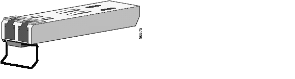
Each SFP must be of the same type as the SFP on the other end of the cable, and the cable must not exceed the stipulated cable length for reliable communications. Figure B-1 shows an SFP module that has a bale-clasp latch.


Caution We strongly recommend that you not install or remove the SFP module while the fiber-optic cable is attached to it because of the potential damage to the cables, to the cable connector, or to the optical interfaces in the SFP module. Disconnect the cable before you remove or install an SFP module.

Removing and installing an SFP module can shorten its useful life. Do not remove and insert SFP modules more often than is necessary.

Figure B-1 SFP Module with a Bale-Clasp Latch


Caution To avoid damaging the cables, follow standard fiber optic cleaning procedures when connecting fiber optic cables to fiber-optic ports.

Replacing SFP Modules into SFP Module Slots

This section describes how to replace an SFP module.


Warning Class 1 laser product. Statement 1008


To insert an SFP module into the SFP module slot, follow these steps:


Step 1 Attach an ESD-preventive wrist strap to your wrist and to a bare metal surface on the chassis.

Step 2 Remove the antenna end cap by using a 3/8-in. wrench to loosen the bolts.

Step 3 Disconnect the LC from the SFP module.


Tip For reattachment, note which cable connector plug is send (TX) and which is receive (RX).


Step 4 Insert a dust plug into the optical ports of the SFP module to keep the optical interfaces clean.


Caution Do not touch the optical surfaces.

Step 5 Unlock and remove the SFP module.

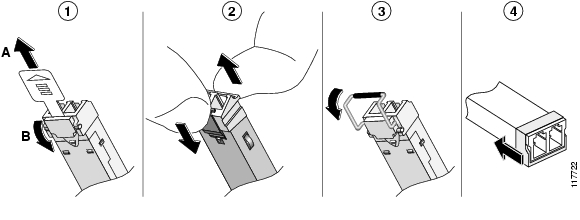
Figure B-2 Disconnecting SFP Latch Mechanisms

Step 6 Pull the bale-clasp latch out and down to eject the module. If the bale-clasp latch is obstructed and you cannot use your index finger to open it, use a small, flat-blade screwdriver or other long, narrow instrument to open the bale-clasp latch.

Step 7 Grasp the SFP module between your thumb and index finger, and carefully remove it from the module slot.

Step 8 Place the removed SFP module in an antistatic bag or other protective environment.


Caution Do not remove the rubber plugs from the SFP module port or the rubber caps from the fiber-optic cable until you are ready to connect the cable. The plugs and caps protect the SFP module ports and cables from contamination and ambient light.

Step 9 Find the send (TX) and receive (RX) markings that identify the top side of the replacement SFP module.


Note On some SFP modules, the send and receive (TX and RX) markings might be replaced by arrows that show the direction of the connection, either send or receive (TX or RX).


Step 10 Align the SFP module in front of the slot opening.

Step 11 Insert the SFP module into the slot until you feel the connector on the module snap into place in the back of the slot.

Step 12 Remove the dust plugs from the SFP module optical ports. Store the plugs for later use.


Caution Do not remove the dust plugs from the SFP module port or the rubber caps from the fiber-optic cable until you are ready to connect the cable. The plugs and caps protect the SFP module ports and cables from contamination and ambient light.

Step 13 Clean the fiber-optic connectors by using standard procedures.

Step 14 Insert the LC cable connector into the SFP module.

Step 15 Verify that the gasket is in place and replace the Antenna end cap by using a 3/8-in. wrench to remove the bolts, torquing the bolts to 58 to 68 inch-pounds.


Diagnosing SFP Problems

You can get statistics from the browser interface, from the CLI, or from an SNMP workstation.

Common SFP module problems fall into these categories:

Poor performance

No connectivity

Corrupted software

Table B-1 describes how to detect and resolve these problems.

Table B-1 Common SFP Problems 

Symptom
Possible Cause
Resolution

Poor performance or excessive errors

Cabling distance exceeded.

Port statistics show excessive frame check sequence (FCS), late-collision, or alignment errors.

Reduce the cable length to within the recommended distances.

See your SFP module documentation for cabling guidelines.

No connectivity

Incorrect or bad cable

The cable is wired incorrectly.

STP checking for possible loops.

Verify the pinouts are correct for the proper application of cables.

Replace the cable with a tested good cable.

Wait 30 seconds for the port LED to turn green.

The port is placed in error-disabled state after SFP module is inserted

Bad or non-Cisco-approved SFP module.

Remove the SFP module and replace it with a Cisco-approved module. Use the errdisable recovery cause gbic-invalid global configuration command to verify the port status, and enter a time interval to recover from the error-disable state.

The port is placed in error-disabled state after SFP is inserted

Bad or non-Cisco-approved SFP module.

Remove the SFP module from the switch and replace it with a Cisco-approved module. Use the errdisable recovery cause gbic-invalid global configuration command to verify the port status, and enter a time interval to recover from the error-disable state.

Device does not recognize the SFP module

The SFP module might be installed upside down.

The SFP module did not snap into the slot.

Verify that the SFP module is not installed upside down.

Remove the SFP module. Inspect for physical damage to the connector, the module, and the module slot.

Replace the SFP module with a known good SFP module.

Excessive errors found in port statistics

Bad adapter in attached device or STP checking for possible loops.

Run adapter card diagnostic utility and wait 30 seconds for the port LED to turn green.


Error Messages

Error Message    Transceiver module inserted in port

Explanation    The online insertion and removal (OIR) facility detected a newly inserted transceiver module for the interface specified in the error message.

Error Message    INIT_FAILURE: Detected for transceiver module in port, module disabled

Explanation    An initialization failure occurred for the transceiver module for the interface specified in the error message. This condition could be caused by software, firmware, or hardware problem. As a result of the error, the module is disabled.

Recommended Action    Try reseating the module. Hardware replacement should not occur first occurrence. Before requesting hardware replacement, review troubleshooting logs with a technical support representative.

Error Message    NOT_IDENTIFIED: Detected for transceiver module in %s, module disabled

Explanation    The transceiver module for the interface specified in the error message could not be identified and may not be compatible with the interface. The transceiver module specified in the error message contains a transceiver code which could not be correctly interpreted. As a result of the error, the module is disabled.

Recommended Action    Replace the module with a compatible transceiver.

Error Message    UNSUPPORTED-TRANCEIVER: Unsupported SFP transceiver found on board. Warranty/support may void

Explanation    The transceiver module for the interface specified in the error message is not a Cisco supported module. As a result of the error, the module is disabled. When Cisco determines that a fault or defect can be traced to the use of third-party transceivers installed by a customer or reseller, then, at Cisco's discretion, Cisco may withhold support under warranty or a Cisco support program. In the course of providing support for a Cisco networking product Cisco might require that the end user install Cisco transceivers if Cisco determines that removing third-party parts will assist Cisco in diagnosing the cause of a support issue.

Recommended Action    None.


hometocprevnextglossaryfeedbacksearchhelp

Posted: Sun Feb 10 06:22:48 PST 2008
All contents are Copyright © 1992--2008 Cisco Systems, Inc. All rights reserved.
Important Notices and Privacy Statement.