|
|

Table Of Contents
I/O End Caps for the Cisco 3200 Rugged Enclosures
Gigabit Ethernet Signal Limitations
Cisco 3200 Rugged Enclosure LED Indications
Cisco 3270 Rugged Enclosure I/O End Cap LED Indications
Cisco 3230 Rugged Enclosure I/O End Cap LED Indications
Cisco 3200 Rugged Enclosures
This chapter provides an overview of the Cisco 3200 Rugged Enclosures so that simple troubleshooting, such as reconnecting a loose cable, can be performed in the field. The chapter is not intended as a complete guide to the chassis, because the devices should be serviced or repaired by a qualified personnel.
The enclosure seals the Cisco 3200 Series router cards so that they can withstand the harsh environments that are common in police cars, military vehicles, trains, airborne vehicles, and outdoor locations that are exposed to the elements.
Cisco 3200 Rugged Enclosure features include:
•
Symmetrical mounting holes for the mounting brackets, so that the unit can be mounted upside-down if required.
•
•
The Cisco 3200 Rugged Enclosures are available as:
•
•
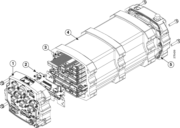
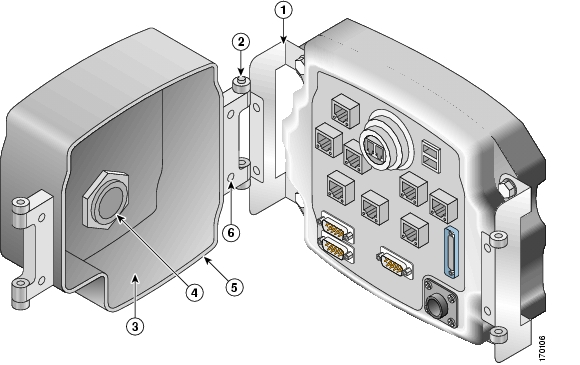
Figure 1-1 shows an exploded view of a Cisco 3230 Rugged Enclosure. (The design of the longer
Cisco 3270 Rugged Enclosure is similar.)Figure 1-1 Exploded View of a Rugged Enclosure
I/O end cap1
Wiring card
Card stack
Extrusion (body of the enclosure)
Antenna end cap
1 This end cap shows four serial ports, but the typical configuration has two serial ports.
The enclosures are sealed by using O-rings between the extrusion and the end caps.
Cisco 3270 Rugged Enclosure
The Cisco 3270 Rugged Enclosure operates in a temperature range from -40 to +165ΑF (-40 to +74ΑC) when all ports are copper. If the Cisco 3270 Router includes a fiber-optic port, it operates at a temperature range from -40 to +147ΑF (-40 to +64ΑC).
The Cisco 3270 Rugged Enclosure is designed to meet NEMA4 requirements. Figure 1-2 shows an example of a fully assembled Cisco 3270 Rugged Enclosure. Note the greater length to accommodate the Cisco 3270 Rugged Router card and future expansion.
Figure 1-2 Cisco 3270 Rugged Enclosure
Cisco 3270 Router Card Stack
The Cisco 3270 Rugged Enclosure supports the following configurations:
•
•
•
•
•
A base configuration includes one of each of the following: Cisco 3270 Rugged Router card, SMIC, FESMIC, and MRPC.
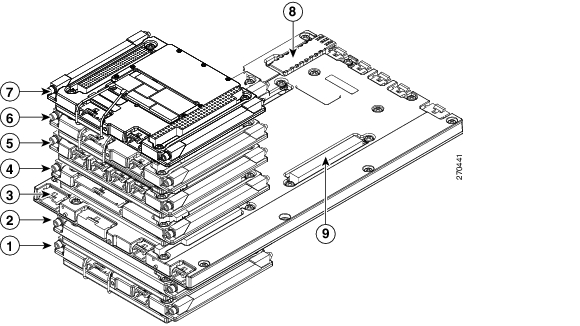
In the Cisco 3270 Rugged Enclosure, the cards should be stacked in the order shown in Figure 1-3. The figure includes three optional WMICs. If WMICs are added, the first WMIC should be installed on the bottom of the stack, and the next two WMICs should be installed at the top of the stack.
Figure 1-3 Example of a Cisco 3270 Router Card Stack with Three Optional WMICs
WMIC 1
MRPC
MARC
SMIC
FESMIC
WMIC 2
WMIC 3
Small-form-factor pluggable (SFP) module
Second PCI bus
Cisco 3230 Rugged Enclosure
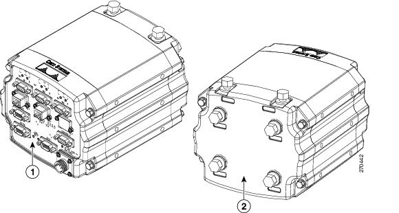
The Cisco 3230 Rugged Enclosure is designed to accommodate the Mobile Access Router Card (MARC). This enclosure operates in a temperature range from -40 to 165ΑF (-40 to +74ΑC), and is certified to meet NEMA4 requirements. Figure 1-4 shows an example of a Cisco 3230 Rugged Enclosure.
Figure 1-4 Cisco 3230 Rugged Enclosure
Front of the enclosure (I/O end cap)1
Back of the enclosure (antenna end cap)
1 This end cap shows four serial ports, but the typical configuration has two serial ports.
Cisco 3230 Router Card Stack
The Cisco 3230 Rugged Enclosure can accommodate up to seven cards, including:
•
•
•
•
•
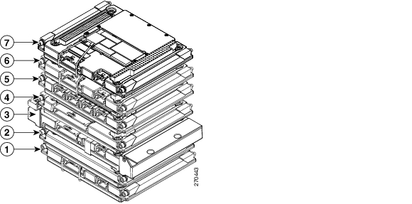
A basic configuration includes one of each of the following: MARC, SMIC, FESMIC, WMIC, and MRPC.
In the Cisco 3230 Rugged Enclosure, the cards should be stacked in the order shown in Figure 1-5. The two optional WMICs are on the top of the stack.
Figure 1-5 Cisco 3230 Router Stack
Rugged Enclosure End Caps
Each Cisco 3200 Rugged Enclosure has two end caps: an antenna end cap that connects to the back of the enclosure, and an I/O end cap that connects to the front of the enclosure. The port configurations of the I/O end caps vary, based on the contents of the enclosure. For example, the number and location of antenna ports installed on the antenna end cap depend on how many WMICs are installed in the enclosure.
Note
Antenna End Cap
The antenna end cap has four antenna ports on the flat side and two ports on the top surface. The end cap is used with the Cisco 3270 Rugged Enclosure or the Cisco 3230 Rugged Enclosure. The antenna ports are connector type RP-TNC. Each RP-TNC is connected internally to a WMIC. Typically, two antenna ports are used to support each WMIC. If fewer than three WMICs are installed, the unused antenna connector ports are sealed with a cap to protect them from the environment.
Figure 1-6 Cisco 3200 Rugged Enclosure Antenna End Cap with a Mounting Bracket
Note
Note
and the "Antenna Cabling" technical note at http://www.cisco.com/en/US/tech/tk722/tk809/technologies_tech_note09186a00801c12c2.shtmlI/O End Caps for the Cisco 3200 Rugged Enclosures
The I/O end cap has multiple connectors for connecting power and data cables. The end cap configurations shown in this section are fully populated; however, the number of ports and their functions may differ, depending upon the number of WMICs in the system.
End Cap Fast Ethernet and WMIC Console Ports
Internally, five Fast Ethernet ports are available: one routed Fast Ethernet port on the router card and four switched Fast Ethernet ports on the Fast Ethernet Switch Mobile Interface Card (FESMIC). When a WMIC is installed in addition to the router, the WMIC Fast Ethernet port is connected internally to the routed Fast Ethernet port on the router card or is connected to one of the switched Fast Ethernet ports on the FESMIC to provide a communications link with the router. In contrast, the Serial Mobile Interface Card (SMIC) and FESMIC communicate with the router through the bus. All the router Fast Ethernet ports are addressed by using the slot/port format.
In typical configurations, the first WMIC Fast Ethernet port is connected to the routed Fast Ethernet port on the router card. The Fast Ethernet ports of the second and third WMICs are connected to FESMIC switched Fast Ethernet ports. The differences in the types of the router Fast Ethernet ports that the WMICs are connected to affect how they are configured, as, for example, when uploading a Cisco IOS image to a WMIC.
The WMIC runs an independent Cisco IOS image and when you configure the WMIC, the link forms an internal LAN. In standard configurations, the WMIC Fast Ethernet port is never brought out to the end cap.
The WMIC console port is brought out to the corresponding RJ-45 port on the I/O end cap, replacing a Fast Ethernet port. If the router includes one WMIC, the EIA/TIA-232 WMIC console port replaces a Fast Ethernet port on the end cap. If the router includes two WMICs, two WMIC EIA/TIA-232 console ports replace two Fast Ethernet ports on the end cap.
Note
Cisco 3270 Router I/O End Cap
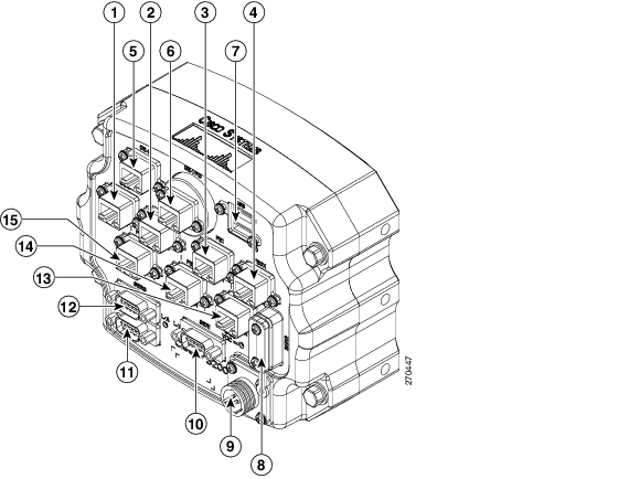
Figure 1-7 shows the Cisco 3270 Router I/O end cap.
Figure 1-7 Cisco 3270 Router End Cap
Router console port
FE0 port
FE1 port
FE0X port
GE0 (Gigabit Ethernet) port
Fiber-Optic port (shown) or Copper Gigabit Ethernet (GE1) port
USB0 (bottom) and USB1 (top) ports
Ser2 Smart Serial port
Power input
Ser1 EIA/TIA-232 (DCE) port
AUX port
Ser0 EIA/TIA-232 (DCE) port
FE1X port or WMIC 3 console port1
FE2X port or WMIC 2 console port1
FE3X port or WMIC 1 console port1
1 The configuration of the port is set at the factory and labeled accordingly.
The RJ-45 connectors identified as 8, 9, and 10 are Fast Ethernet ports or WMIC console ports, depending on the configuration of the system. For example, if two WMICs have been added to the router, RJ-45 ports 8 and 9 are labeled WMIC 1 and WMIC 2. Port 10 is labeled FE1X.
Note
Fiber Optic Connector IP-67 Integrity
When the fiber-optic port is not connected or otherwise in use, the protective cover should be used to seal the port. To seal the fiber-optic port when it is connected to a cable, use connectors that maintain IP-67 integrity. The part numbers for the connectors are Tyco 1828618-1 and Tyco 1828618-2.
Caution
Power Connector IP-67 Integrity
To seal the Tyco DC Power input power connector and maintain IP-67 integrity, use the following parts:
•
•
•
•
Smart Serial Port External Seal for System Integrity
When the Smart Serial port is not connected or otherwise in use, the protective cover should be used to seal the port. To seal the Smart Serial port when the port is connected to a cable, complete the steps in Appendix A, "Smart Serial Port External Seal." in the Cisco 3200 Series Router Hardware Reference.
USB Flash Storage Device Caveat
In some cases, using two USB flash storage devices causes unpredictable results (CSCsd11136).
If one USB flash storage device is plugged into a USB port and a second USB flash storage device is plugged into or unplugged from the other port, an error might occur (CSCsd44152). The error message is, "USB_HOST_STACK-6-USB_FLASH_READY_TEST_TIME: USB flash 'Ready' test time over
4 seconds."If an unsupported USB flash storage device is plugged into a USB port, an error might occur (CSCsd44152). The error message is, "Failed to enumerate a USB device as not able to read the device's description."
To correct the problems, remove any unsupported USB flash storage device and use only one supported device in one of the two USB ports. The Cisco-supported flash storage devices listed below.
Cisco 3230 Router I/O End Cap
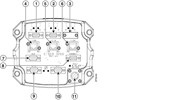
Figure 1-8 shows the Cisco 3230 Router I/O end cap. It has multiple connectors that can be used to connect power and data cables.
Figure 1-8 Cisco 3230 Router End Cap
WMIC 1 console port
WMIC 2 console port
WMIC 3 console port
FE0 port
FE1X port
FE2X or MARC FE0X port (for more information, see the "Fast Ethernet Port Cabling for the Cisco 3250 and Cisco 3230 Routers" section.)
AUX port
Router console port
Ser0 RS-232 (DCE) port
Ser1 RS-232 (DCE) port
Power input
Note
Protective End Cap Cover
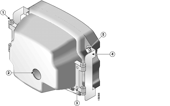
A protective end cap cover ( Figure 1-9) provides weatherproof protection for the ports on the end caps of the Cisco 3200 Rugged Enclosure when the enclosure is installed outdoors. The protective end cap cover also provides added protection for in-vehicle use, inhibiting corrosion on the ports and potential damage from objects that are stored near the enclosure inside a vehicle.
The protective end cap cover has a ruggedized design for high reliability and NEMA4 compliance.
Figure 1-9 Cisco 3200 Rugged Enclosure Protective End Cap Cover
Hinge point
NEC cable pass-through
Holes for 8-32 protective end cap cover screws
Hinge/mounting bracket
Mounting bolt
To attach the protective end cap cover to the enclosure, follow these steps (see Figure 1-10).
Figure 1-10 Protective End Cap Cover Installation
Hinge bracket
Hinge point
Cable/service loop cavity
NEC pass-through
Gasket
Cap mounting
Step 1
Step 2
Step 3
Step 4
Step 5
Step 6
Step 7
For sealing, we recommend Liquid Tight Connector, which is described at the following URL:
http://www.newark.com/NewarkWebCommerce/newark/en_US/mfr/brands.jsp?mfg=HUBB
I/O End Cap Port Signals
This section describes the ports and port signals on the Cisco 3200 Rugged Enclosure I/O end caps.
Gigabit Ethernet Signal Limitations
Due to CPU and memory bus limitations, a Gigabit Ethernet port transmits and receives packets below the line rate. The line rate is lower for small frames and higher for large frames.
Small packet streams on Gigabit Ethernet ports, such as 64-byte packet streams, support up to 24 percent of full duplex, bidirectional line rate traffic without experiencing packet drops.
The 512-byte packet streams support up to 78 percent of full duplex, bidirectional line rate traffic. The 1518-byte packet streams support up to 88 percent of full duplex bidirectional line rate traffic.
At higher frame rates the RDRP receive drop counter (displayed by using the show controller g0/0 command) increases indicating dropped packets.
At higher frame rates for packet sizes greater than 512 bytes, the transmit underruns1 counter (displayed by using the show int g0/0 or show int g0/1 command) increases. The transmit underruns might cause CRC errors on the peer router.
Fast Ethernet Signals
A Cisco router identifies a Ethernet port interfaces by slot number and port number in the format of slot/port. For example, the slot/port address of a Fast Ethernet interface on the Cisco 3230 Rugged Enclosure is 0/0.
The Cisco 3270 Router Ethernet port signals are in compliance with IEEE 802.3. The interfaces support the following:
•
•
•
•
•
•
•
•
•
•
•
•
The Cisco 3230 Router Ethernet port signals are in compliance with IEEE 802.3. The interfaces support the following:
•
•
•
•
•
•
•
•
Fast Ethernet Port Cabling for the Cisco 3250 and Cisco 3230 Routers
Most Cisco 3200 Series router Ethernet ports support autodetection. If the device that the router is connected to also supports autodetection, the choice of a straight-through or crossover Ethernet cable does not matter. However, the Cisco 3250 router MARC FE0X port does not support autodetection.
To connect a port marked MARC FE0X to a routing Ethernet port that does not support autodetection, use a straight-through Ethernet cable. To connect a MARC FE0X port to a hub, switch, a router hub, or switch port, use a crossover Ethernet cable. Table 1-1 shows the connections.
For example, a port marked FE0X requires a crossover Ethernet cable to establish the Ethernet link between a Cisco 3250 router and a hub. A port that does not support autodetection marked FE0 requires a straight-through Ethernet cable to establish the Ethernet link between a Cisco 3250 router and a hub.
For additional information on cable pin assignments, see the "Cable Pinouts" chapter of the Cisco Content Services Switch Getting Started Guide at:
http://www.cisco.com/en/US/products/hw/contnetw/ps789/products_installation_guide_chapter09186a00805f718d.html
Console Port Signals
You can connect to the router or to a Wireless Mobile Interface Card (WMIC) by using a console cable to connect to the console interfaces.
The console port signals:
•
•
•
AUX Port Signals
The AUX port is a serial asynchronous port that supports the following speeds:
•
•
The AUX port supports the following:
•
•
•
•
•
Cisco 3200 Rugged Enclosure LED Indications
This section describes the LED indications for the Cisco 3200 Rugged Enclosure I/O end caps.
Note
Cisco 3270 Rugged Enclosure I/O End Cap LED Indications
Table 1-2 lists the LEDs for the Cisco 3270 Rugged Enclosure I/O end caps and their indications.
Table 1-2 LEDs for the Cisco 3270 Rugged Enclosure End Cap
Cisco 3270 Rugged Router card
Solid green: OK.
Blinking: Booting and self-testing.
Black: Not OK or the power is off.Serial Status/Link (1 status/link LED per serial port)
Solid green: Link OK.
Black: No link is detected.
Amber blink: Activity.Fast Ethernet
(1 LED per port, except for the fiber-optic port, which has no LEDs)Link LED
Solid green: Link OK.
Black: No link is detected.Activity LED
Black: No activity and no connection.
Green blink: Activity.Gigabit Ethernet
(2 LEDs per port)Link LED
Solid green: Link OK.
Black: no link is detected.Activity LED
Solid green: Link OK.
Black: No activity.
Green blink: Activity.Console
Solid green: Link OK.
Black: No activity.
Green blink: Activity.WMIC Console (Installation or Operation Mode)
For installation mode, see Table 1-4.
For operation mode, see Table 1-5.
Cisco 3230 Rugged Enclosure I/O End Cap LED Indications
Table 1-3 lists the LEDs for the Cisco 3230 Rugged Enclosure I/O end caps and their indications.
Table 1-3 LEDs for Cisco 3230 Router I/O End Caps
MARC
Solid green: OK.
Blinking: Booting and self-testing.
Black: Not OK or the power is off.Serial Status/Link (1 status/link LED per serial port)
Solid green: Link OK.
Black: No link is detected.
Amber blink: Activity.Fast Ethernet (2 LEDs per Fast Ethernet port)
Link LED
Solid green: Link OK.
Black: No link is detected.Activity LED
Black: No activity.
Green blink: Activity.WMIC Console (Installation or Operation Mode)
For installation mode, see Table 1-4.
For operation mode, see Table 1-5.
WMIC Console LEDs
WMIC console LEDs function in installation mode or operational mode. The WMIC is set to the installation mode by default. To change the function of the WMIC, use the station role command.
Table 1-4 shows the status of the LEDs when the WMIC is in installation mode (signal strength).
Table 1-5 shows the status of the LEDs when the WMIC is in operational mode.
Thermal Plates
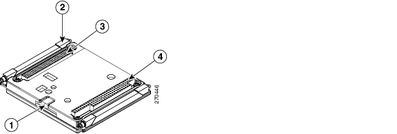
Cisco 3200 Rugged Enclosures use thermal plates and Wedge Loks to transfer heat from the cards to the extrusion. Figure 1-11 shows a card with thermal plates. The conduction cooling removes the need for internal fans.
Figure 1-11 Router Card with Thermal Plates
Mounting Brackets
Mounting brackets are available for the enclosures.
The notches in the mounting brackets allow you to temporarily install the bracket without the router in place. The bolts for the notches in the mounting bracket can be installed on the enclosure before the other bolts are installed. The partially installed bolts provide enough support to allow you to install the router in the bracket, and then install and tighten the remaining bolts. The torque values for the mounting bracket screws are from 58 to 68 in-lb.
Figure 1-12 shows the Cisco 3270 Rugged Enclosure mounting bracket.
Figure 1-12 Cisco 3270 Rugged Enclosure Mounting Bracket
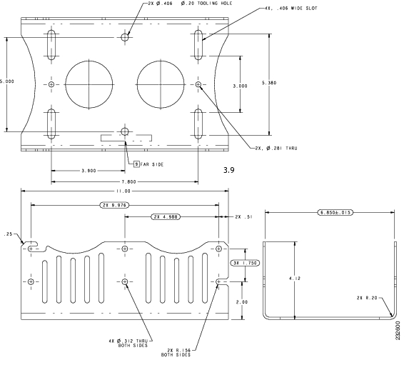
Figure 1-13 shows the dimensions of the Cisco 3270 Rugged Enclosure mounting bracket.
Figure 1-13 Cisco 3270 Rugged Enclosure Mounting Bracket Dimensions
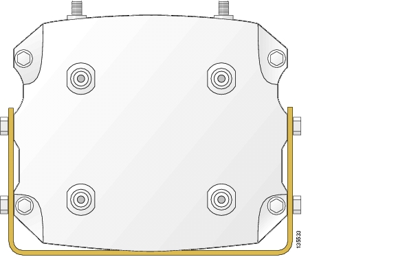
Figure 1-14 shows the Cisco 3230 Rugged Enclosure mounting bracket.
Figure 1-14 Cisco 3230 Rugged Enclosure Mounting Bracket
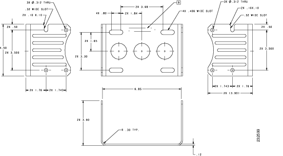
Figure 1-15 shows the dimensions of the Cisco 3230 Rugged Enclosure mounting bracket.
Figure 1-15 Cisco 3230 Rugged Enclosure Mounting Bracket Dimensions
1 Transmit underrun-an error on interfaces when the data is not ready on the memory bus when the system attempts to transmit the data; a bad packet is transmitted.
![]()
![]()
![]()
![]()
![]()
![]()
![]()
![]()
Posted: Sun Feb 10 06:42:07 PST 2008
All contents are Copyright © 1992--2008 Cisco Systems, Inc. All rights reserved.
Important Notices and Privacy Statement.