|
|

| Prepare Your Installation Site |
You must do three procedures when unpacking and installing your Cisco AccessPath-TS3 Model 531 Integrated Access System:
1. Unload the crate from its shipping vehicle.
2. Move the crate using a forklift or similar device to the unpacking site.
3. Move the unpacked system to the installation site.
Consider the following issues before you unpack and install your system:
Cisco recommends that five people be
present whenever you move the Cisco AccessPath-TS3 Model 531 system cabinet. Plan adequate human resources to unload and install the system—the fully loaded system can weigh up to 1300 lbs (590 kg), and moving it carelessly can cause serious injuries.
Cisco recommends that you use a bolt kit from HILTI. This kit has passed seismic testing when used with the Cisco AccessPath-TS3 Model 531 system. If you use a bolt kit from another vendor (or if you supply your own), it is your responsibility to confirm the fulfillment of seismic safety standards.
The recommended kit can be ordered from HILTI, and includes the following elements:
In addition, you will use the load plate that you saved when you unbolted the system from its shipping pallet.
Confirm that you have the following tools available:
 | Warning Before installing the Cisco AccessPath-TS3 system, refer to the warnings listed in the document Regulatory Compliance and Safety Information for the Cisco AccessPath-TS3 Model 531 System. |
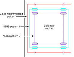
Cisco's seismic safety guidelines include bolting patterns that conform to Network Equipment Building Standards (NEBS) requirements.
To ensure seismic safety, you must anchor the cabinet to the floor as follows:
Step 2 Insert casings (anchors) in the holes.
Step 3 Secure the system to the anchors using threaded rods.
The illustration below shows the three possible bolt patterns:
| Uncrate and Move the System |
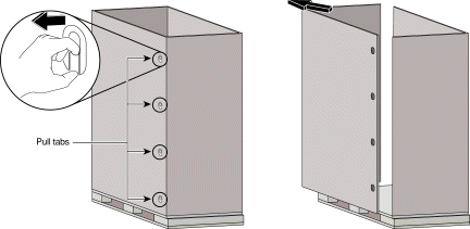
1 Place your index finger inside the top corner pull tab locking mechanism, and pull it toward you.
2 Remove the detachable lock and set it aside.
3 Repeat this process for the remaining three locks that secure this side.
4 Go to the other side of the unit and repeat Step 1.
Step 2 Store the three cardboard pieces in a a safe and dry place.
One metal band binds these kits to the pallet as shown in the figure on page 4.
Do the following steps to remove the accessories kits from their shipping positions:
Step 2 Remove the band and lift the kits out of the cabinet.
System accessory kits include the following:
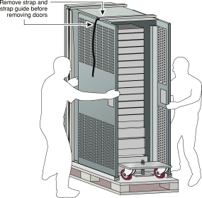
Do the following steps to remove the doors from their shipping positions:
Step 2 While a second person holds the doors, use tin snips to cut the metal strap that binds the doors to the side of the cabinet. Discard the straps and strap guides.
Step 3 Have a second person hold the doors while you grasp the edges of one door and lift it carefully out of its retaining u-stock. Assign a second person to hold the second door on the opposite side of the cabinet.
Step 4 Set the door down in a stable position or carry it to the installation site. You will attach the doors to the cabinet at the end of the installation procedure.
Step 5 Lift the second door out of its retaining material and place it with the first door.
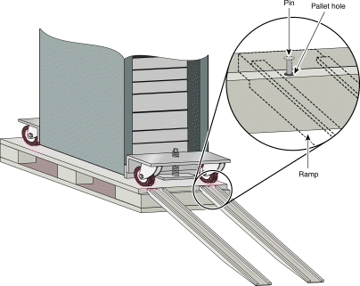
Do the following steps to prepare the ramp for use:
Step 2 Lift one of the ramp legs clear of the cabinet and carry it to the side of the pallet from which you will unload the system.
Step 3 Align the ramp leg so that the hole at its end is directly over one of the pins on the edge of the pallet. Lower the ramp leg until the peg fits securely into the hole in the wood.
The first of the two ramp legs is now locked into position.
Step 4 Repeat Step 2 and Step 3 with the second ramp leg, aligning it with the uncovered pin.
Step 5 Confirm that the ramp's holes are securely locked around the pins.
Do the following steps to unbolt the unit:
Step 2 Remove and save the 2- x 3-inch (5.1- x 7.6-cm) load plates that sit beneath the nuts. (You will use these for seismic safety bolting.)
Step 3 Push the loosened bolts through the pallet so they fall to the floor.
Step 4 Make sure that all four bolts drop completely through the pallet to the floor and do not obstruct the casters or the cabinet.
Assign one person to control the front caster assembly and one person the back assembly. Now raise the system:
Step 2 Turn the wrench clockwise to lower the casters and raise the cabinet.
Step 3 Continue to lower the front and back casters in a coordinated fashion until all four wheels barely touch the pallet surface.
Step 4 Align the front and back caster wheels using your hands until they are parallel with each other and face the attached ramp legs. Be sure that no one is turning the caster assembly as you align the wheels.
Step 5 Raise the entire assembly 1.5 inches (3.8 centimeters) to ensure that the cabinet clears the ramp. Otherwise, the cabinet might catch on the ramp lip.
 | Warning We recommend that four people work together to roll the cabinet down the ramp and to the installation site. Using fewer than three people will substantially increase the risk to personnel and equipment. |
Step 6 Position yourself and the remaining personnel in the most efficient configuration. (Refer to the following figure.) A fifth person should be present as a safety observer. If, as recommended, you have assigned four people to move the system, position each at a corner of the cabinet. If only three people are available, place one in front and one on each side.
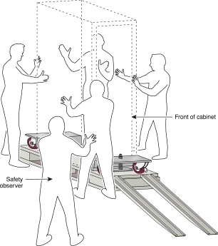
Step 7 Roll the Cisco AccessPath-TS3 system down the ramp at a controlled but steady speed.
Step 8 After all four casters have reached the floor, roll the cabinet to the installation site. Remove, or route the cabinet around, any protrusions or obstacles between the unload and the installation locations. Move the cabinet at a controlled but steady speed.
Step 9 After you have reached the installation site, move the cabinet into position over the bolt holes. See the "Install the Cabinet" section in Chapter 3 of the Cisco AccessPath-TS3 Model 531 Integrated Access System Hardware Installation Guide.
After moving the Cisco AccessPath-TS3 Model 531 system to the installation site, do the following steps to install your system:
Step 2 Align the mounting holes in the cabinet with the holes in the floor.
Step 3 Collect the four threaded rods that anchor the system to the floor. Place them all within reach. (Each comes with a washer and a nut used to secure the rod in the casing. A load plate, also required to secure the rod, ships with the system packaging.)
Step 4 Locate the first mounting hole on the base of the cabinet. Hand-turn the threaded rod into the casing until it stops. Do not attempt to tighten the thread any further now; you will do that in a later step.
Step 5 Repeat Step 4 for the remaining threaded rods.
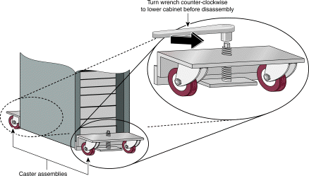
Step 6 Raise the casters to lower the system completely to the floor (Refer to the illustration below.)
1 With one person stationed at each caster assembly, attach the appropriate wrench to the turning mechanism (wormscrew) on each caster plate.
2 Turn the wrench counter-clockwise until the cabinet is completely on the floor and the casters are completely clear of the floor.
3 When the system makes contact with the floor, confirm that both caster assemblies no longer touch the floor.
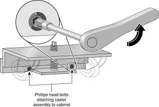
Step 7 Detach the caster assembly:
1 Locate the two bolts that connect the first assembly.
2 Using an allen wrench, loosen the nut on the first bolt. Remove the bolt and set it aside.
3 Repeat this process for the second bolt on the first caster assembly.
4 Detach the rest of the assembly from the cabinet, and set all components in a safe place for future use.
5 Remove the studs in the cabinet.
Step 8 Repeat Step 7 to disassemble the second caster assembly.
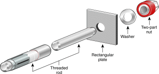
Step 9 Tighten down each of the threaded rods using a torque wrench.
1 Place the metal load plate over the first threaded rod (already set in its anchor). Align the hole in the plate over the threads, and lower it until it is flush with the top of that section.
2 Place a washer over the rod and let it drop onto the plate.
 | Caution These nuts will shear when 60 ft-lbs are reached—you should use a box-end or 19-mm socket wrench to turn them. |
3 Place the nut assembly onto the top of the threaded rod and tighten it down. Continue to tighten the nut with the torque wrench until the visible metal portion shears away (this will occur when the assembly is torqued to a tension of 60 ft-lbs).
4 Repeat Step 9 for each of the remaining three threaded rods until you have securely bolted the cabinet into the floor.
Though the Cisco AccessPath-TS3 system is precabled, you must ensure that all connectors are securely seated.
| Step | Device | Cable | Shelf Connection | Signal Harness Connection |
|---|---|---|---|---|
1 | Patch panels | 72-1466-xx | J1-J4 | J2 (Patch panel 1) |
J5-J7 | J1 (Patch panel 1) | |||
2 | Access Server Shelves | 72-1464-xx | PRI 0-PRI 3 | Odd-numbered connectors, |
72-1463-xx | Console 0 | Even-numbered connectors, | ||
4 | Router Shelves
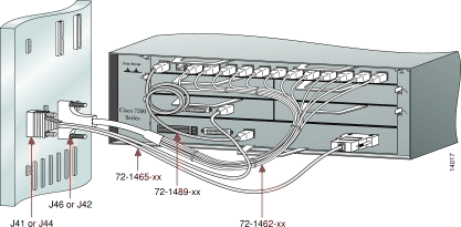
| 72-1462-xx | The 12 Ethernet switching ports | J46 (Router Shelf 1) |
72-1465-xx | Console 0 Ethernet 0 | J44 (Router Shelf 1) J41 (Router Shelf 2) | ||
72-1487-xx1 | The 12 Ethernet switching ports | J56 | ||
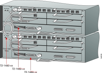
72-1489-xx | Router Shelf Fast Ethernet port 5/0 Router Shelf 1 Fast Ethernet port 3/0 | Router Shelf port 0/01 Router Shelf 1 port 0/02 | ||
72-1490-xx2 | Router Shelf 1 Fast Ethernet port 5/1 | Router Shelf 2 | ||
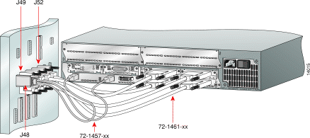
5 | System Controller | 72-1461-xx | Async 0-7 Async 8-15 Async 16-23 Async 24-31 | J49 J50 J51 J52 |
72-1457-xx | Ethernet 0-1 | J48 | ||
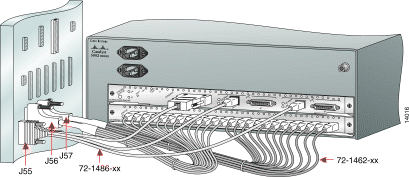
6 | Switch Shelf | 72-1462-xx | The 24 Ethernet switching ports, | J56 |
72-1486-xx | Console Ethernet | J55 |
All signal cabling configurations should look like this on patch panels:
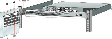
All signal cabling configurations should look like this on 4-PRI Access Server Shelves:
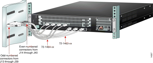
All signal cabling configurations should look like this on 8-PRI Access Server Shelves:
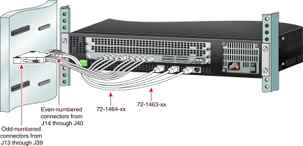
All signal cabling configurations should look like this on Router Shelves:
High-End configurations must include the interconnect cables on Router Shelves:
All signal cabling configurations should look like this on the System Controller:
All signal cabling configurations should look like this on the Switch Shelf:
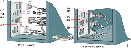
On the High-End/Extended configuration, you must cable the devices in the secondary cabinet to those in the primary cabinet using five expansion cables. The maximum space between the cabinets is 30 feet (9.14 m).
| Step | Connect Cable Part Number | From the Primary Cabinet Signal Harness Location | To the Secondary Cabinet Signal Harness Location |
1 | 72-1459-xx | J43 | J46 |
2 | 72-1458-xx | J47 | J45 |
3 | 72-1460-xx | J53 | J49 |
4 | 72-1460-xx | J54 | J50 |
5 | 72-1459-xx | J58 | J56 |
Do the following steps to install the AC Out-of-Band (OOB) Modem:
Step 2 Attach the power cable to the supplied extension cord, which converts a 2-prong connector to a 3-prong connector that fits the power strip.
Step 3 Insert the modem adapter (29-0881-xx) in the serial port at the back of the modem. Tighten the screws to secure the connection.
Step 4 Take the modem, velcro strap, and related installation components to the back of your Cisco AccessPath-TS3 system.
Step 5 Locate the modem bracket found in the right rear corner of the system when viewed from the back. This bracket, which forms a metal pouch for easy modem installation, is premounted against the wall of the system.
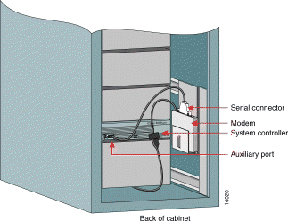
Step 6 Position the modem above the metal pouch at the center of the bracket. Insert the modem so that the ports and modem adapter are at the top. (Refer to the illustration below.)
Step 7 Take the velcro strap and loop it around the back of the modem and through the bridge lance that attaches to the outside of the installation pouch.
Step 8 Wrap the velcro tightly and press the strips together, securing the modem in the metal installation pouch.
Step 9 Attach the power cord to the modem port located at the top left edge of the installed modem. (If you have not connected the modem power cord to the supplied extension cord, do so now.)
1 Grasp the extension cord with the 3-prong connector, and route it from the modem to the AC power strip connector labeled OOB-Modem.
2 Route the extension cord directly beneath the Switch Shelf, pushing the cord through as far as it will reach.
3 Walk to the front of the system and pick up the power cord (it should extend through the opening beneath the Switch Shelf).
4 Plug the extension cord into the connector labeled OOB-Modem.
Step 10 Attach the modem serial connector to the System Controller:
1 If you have not already done so, attach the serial adapter (29-0881-xx) to the center of the modem port array. Use the thin, flat, RJ-45-to-RJ-45 rolled cable (72-0876-xx) with an RJ-45-to-DB-25 adapter.
2 Locate the auxiliary port that is accessible from your location at the rear of the System Controller, and plug the other RJ-45 end into it.
Step 11 Connect your external phone line. Insert one end of the line connector (RJ-45) into the line port and the second connector end into a wall jack.
Step 12 Turn the modem ON. You have now established OOB management to your system.
To connect power to your system, you must first confirm that your site meets the power requirements, which help guarantee power redundancy to the Router Shelf and the Switch Shelf:
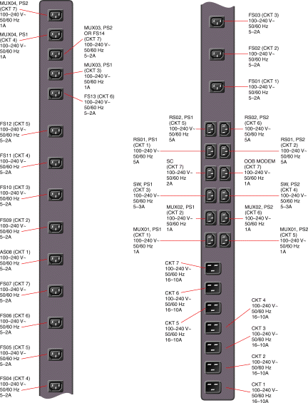
For a Cisco AccessPath-TS3 Model 531 system equipped for AC power, the power is supplied to the various shelves through a power strip located on the right side of the system, inside the front door.
Step 2 Confirm that the AC power connections are firm between the shelves and the power strip. Check the connections in this order:
1 Access Server Shelves
2 Router Shelf or Shelves (depending on configuration)
3 System Controller
4 Switch Shelf (depending on configuration)
5 Out-of-Band Modem (optional)
Step 3 Plug any unconnected power cords that come from the Cisco AccessPath-TS3 system system into the power strip at the appropriate location.
Step 4 Connect each of the AC power input cables that bring power into the system power strip to a separate grounded power source. (This will require seven dedicated 20A (100 to 127 VAC) or 10A (100 to 240 VAC) circuits per cabinet.)
Step 5 Turn each of the shelves ON, one at a time.
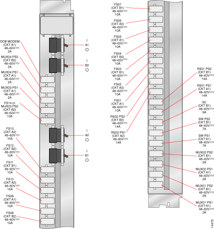
For a Cisco AccessPath-TS3 Model 531 system equipped for DC power, the power is supplied to the various shelves through a DC busbar. This busbar comes with the system and is installed in the system cabinet.
1 Access Server Shelves
2 Router Shelf or Shelves (depending on configuration)
3 System Controller
4 Switch Shelf (depending on configuration)
Step 2 If you need to connect any of the shelves to the DC busbar, do so:
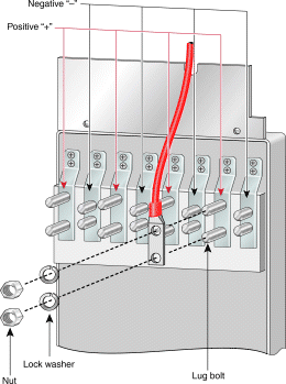
1 Connect the DC busbar to the shelf's power supply: red wire to positive (+), black wire to negative (-).
2 Connect the shelf to the DC busbar using the connector.
Step 3 Connect the main earthing wire to either set of double grounding studs using a 2 to 6 AWG copper-stranded wire crimped to a double lug of the appropriate size. (These studs are located at the top and bottom of the rear of the system.)
Step 4 Remove the DC busbar inlet panel. Connect DC power to the DC busbar. This will require four dedicated 45A (-48 to -60 VDC) circuits per Cisco AccessPath-TS3 system cabinet.
Refer to the wiring method shown in the illustration below, then, with the DC power source turned OFF, connect a 2 to 6 AWG copper-stranded wire to the DC busbar using the provided double lugs and following these guidelines:
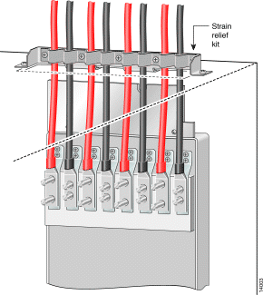
Step 5 Install the strain relief kit at the top of the cabinet:
1 Screw the flat portion of the strain relief kit to the top of the cabinet.
2 Place the rounded portion of the DC strain relief kit around the DC power feeds at the top of the system.
3 Screw the two pieces of the kit together until they grip the power feeds. Do not tighten these screws down now; you will do so in Step 7.
Step 6 Tighten the nuts that connect the DC power feeds to the inlet.
Step 7 Tighten the five screws on the strain relief kit so that they firmly grip the DC power feeds.
Step 8 Replace the DC inlet panel.
Step 9 Make sure that all of the shelves are turned OFF.
Step 10 Turn ON power at the DC power source.
Step 11 Turn each of the shelves ON, one at a time.
You connect to a T1 or E1 network using patch panels, which have either RJ-48C connectors or posts for wire-wrap connections. Regardless of connection type, the port mapping is the same.
Do the following steps to connect to the patch panel wire-wrap connections:
Step 2 Refer to the callouts in the illustration below, then use a wire-wrap tool to connect to the Receive Tip, Receive Ring, Transmit Tip, and Transmit Ring for up to 28 connections per patch panel.

Step 3 Replace the patch panel cover, routing the cables out the right side.
Do the following steps to connect your T1 or E1 network to the patch panel using RJ-48C connections:
Step 2 Route the T1/E1 cables to the right and tie-wrap them so that they do not obstruct other shelves.

Connect to your network backbone through port adapters on the Router Shelf as follows:
Depending on whether you will be connecting to a LAN or a WAN, your backhaul port adapters should be installed as follows:
After installing the correct port adapters, be sure to configure them properly. Refer to the documentation that shipped with your port adapter.
2
2
2
2
2
![]()
![]()
![]()
![]()
![]()
![]()
![]()
![]()
Posted: Tue Jul 16 14:53:58 PDT 2002
All contents are Copyright © 1992--2002 Cisco Systems, Inc. All rights reserved.
Important Notices and Privacy Statement.