Introduction to the Cisco AccessPath-TS3 Model 530 Integrated Access System
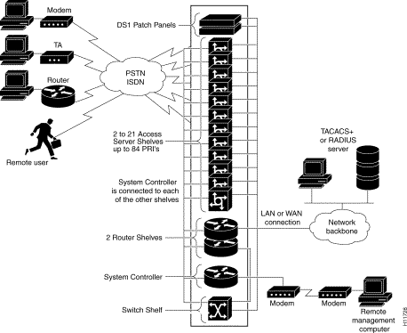
The AccessPath-TS3 system is a scalable, high-density dial system designed to terminate a large number (184 or more PRI, 192 or more modem) of mixed digital and analog calls (see Figure 1-1). The AccessPath-TS3 system provides dial access for service providers deploying large-scale hybrid access ports at a central site. It supports remote node or remote LAN applications that use asynchronous modem or Integrated Services Digital Network (ISDN) technology and includes the latest access server, switching, and high-end routing features available with Cisco IOS software.
The AccessPath-TS3 system integrates high-end access servers, Ethernet switches, and routers into a single Electronic Industries Association (EIA)-standard rack cabinet. It can terminate any combination of analog modem or digital ISDN calls for its incoming lines. Processing tasks—such as answering and terminating calls—are divided among several CPUs, increasing overall system call processing and throughput performance.
The AccessPath-TS3 system offers scalable dial-port counts and high-performance backbone routing in a distributed system architecture. The system provides the reliability and serviceability demanded by point-of-presence (POP) administrators who want to minimize downtime and service costs.
Figure 1-1 AccessPath-TS3 System Configured with 12 Access Server Shelves
Standard Hardware Configurations
The AccessPath-TS3 system comes in four standard configurations. Each of these configurations include
Separate and resilient data and management links
DS1 patch panel, if using T1.
E1/R2 converter, if using E1.
AC or DC power supplies
Cabinet (including rack), to simplify hardware upgrades.
Custom wiring harness and metal wiring channel for cable management.
Hardware and software preconfiguration. The AccessPath-TS3 system arrives racked, cabled, loaded, and tested with default configurations.
The following are examples of the different AccessPath-TS3 system configurations.
Example Configuration 1
This configuration uses the dual-wide Ethernet switch port adapter for its primary switching path.
AC or DC power distribution
2 to 7 Access Server Shelves
Up to 28 Primary Rate Interfaces (PRIs), or CT1/E1 (4 PRIs per Access Server Shelf)
One Router Shelf
Two dual-wide Ethernet switch port adapters
One or two other port adapters
One DS1 patch panel (optional)
One System Controller
Example Configuration 2
This configuration uses a Catalyst 5002 switch for its primary switching path. It provides redundant switching for increased availability.
AC or DC power distribution
2 to 11 Access Server Shelves
Up to 44 PRIs, or CT1/E1 (4 PRIs per Access Server Shelf)
One Router Shelf
Each with one dual-wide Ethernet switch port adapter
One Fast Ethernet module
At least one backhaul module
DS1 Patch Panels supporting up to 56 T1 connections (optional)
One Catalyst 5002 Switch Shelf with a 24-port Fast Ethernet module and two Fast Ethernet ports on the supervisor board
Example Configuration 3
AC or DC power distribution
2 to 14 Access Server Shelves
Up to 56 PRIs, or CT1/E1 (4 PRIs per Access Server Shelf)
2 Router Shelves
Each with one dual-wide Ethernet switch port adapter
Each with one Fast Ethernet module
At least one backhaul module
DS1 patch panels supporting up to 56 T1 connections
1 Catalyst 5002 Switch Shelf with a 24-port Fast Ethernet module and 2 Fast Ethernet ports on the supervisor board
Example Configuration 4
AC or DC power distribution
2 to 21 Access Server Shelves (up to 14 in the first cabinet, up to 7 in the expansion cabinet)
Includes 84 PRIs, or CT1/E1 (4 PRIs per Access Server Shelf)
Two Router Shelves
Each with one dual-wide Ethernet switch port adapter
One Fast Ethernet module
At least one backhaul module
One Catalyst 5002 Switch Shelf with a 24-port Fast Ethernet module and two Fast Ethernet ports on the supervisor board
DS1 patch panels supporting up to 84 T1 connections (optional)
One Ethernet switch with a 24-port Fast Ethernet module and two Fast Ethernet ports on the supervisor board
Features
The AccessPath-TS3 system supports the following features:
Rack-mount system design for easy maintenance and upgrades.
DS1 patch panel for T1 connections.
Universal connector AC power strips.
Nonblocking data backplane (via Ethernet switching).
Out-of-band device management by means of dialup or local terminal access.
Cisco level 2 forwarding (L2F).
Multichassis multilink PPP (MMP).
Full Cisco IOS functionality (Release 11.2(10)P or later). (For more information on Cisco IOS software in the AccessPath-TS3 system, refer to the Cisco AccessPath-TS3 Integrated Access System Software Configuration Guide and the Release Notes for the Cisco AccessPath-TS3 Integrated Access System.)
T1/E1 and Fast Ethernet backhaul interface support.
Automatic sensing of analog modem and digital ISDN calls across the entire rotary, regardless of size.
From 4 to 84 T1 PRI lines with integrated channel service units terminated in a single AccessPath-TS3 system. This allows up to 1932 simultaneous ISDN PRI calls to be terminated in a single T1-configured AccessPath-TS3 system. (For more information on call termination capacity, see Table 1-1.)
From 4 to 84 E1 PRI lines for customers who require E1 service. This allows up to 1260 simultaneous ISDN PRI calls to be terminated in a single E1-configured AccessPath-TS3 system. (For more information on call termination capacity, see Table 1-1.)
From one to six port adapter (PA) slots that take standard Cisco Versatile Interface Processor (VIP) PA cards.
PA slots can be configured to use a wide variety of Cisco port adapter cards, protecting customer investment and simplifying sparing.
Preconfiguration and precabling of hardware.
Preloaded custom or sample (typical) configurations of Cisco IOS software.
Full management of all components including access servers and their modems, switches, and routers by means of the Simple Network Management Protocol (SNMP), management information bases (MIBs), or the Cisco AccessPath Manager software.
Full management of all components by means of a single management interface when using the AccessPath Manager software. Parameters and statistics gathered across all the dial interfaces of the AccessPath-TS3 system are presented in one place.
Failsafe processing provided by the redundant data paths (via Ethernet and Fast Ethernet links).
Universal Access
The AccessPath-TS3 system allows dial point of presence (POP) managers to deploy large rotary groups in a short period of time. Cisco provides the AccessPath-TS3 system preracked, precabled, and preconfigured with custom or sample (typical) configurations. This preconfiguration facilitates system setup and reduces installation and operation costs. We recommend that you use Cisco AccessPath Manager software to simplify configuration.
The design of AccessPath-TS3 system networks that are customized for a specific installation is the responsibility of the customer.
Availability
The AccessPath-TS3 system has no single point of failure. Operating time is maximized and the failure of individual components does not bring down the entire system. This applies to all AccessPath-TS3 system confugurations.
Cisco IOS Software
The AccessPath-TS3 system offers guaranteed compatibility to networks that run Cisco IOS software. (Cisco IOS software runs on most of the world's internetworks, both on Cisco routers and on many other platforms.) The AccessPath-TS3 system supports remote-node and remote-LAN dial protocols. You can use your current training and experience with Cisco IOS software to install, configure, and manage the AccessPath-TS3 system.
Preconfigured Hardware
When you purchase an AccessPath-TS3 system of any size (from 4 to 84 PRIs), we will install, wire, and configure the system for the most popular services available with Cisco IOS software. This reduces the cost of administering a POP because a great deal of the cost of any dial POP is in the physical design, integration, and testing of the equipment involved.
We consider connect rates, throughput, reliability, and manageability as mandatory features of any properly designed dial POP. These are therefore provided as standard features of the AccessPath-TS3 system. By offering alternate data paths from each access server to either one or two offload servers, we provide full redundancy for mission-critical data.
Each AccessPath-TS3 system comes with a System Controller that is dedicated to providing console management of each device in the AccessPath-TS3 system cabinet. This feature increases system resiliency by adding a single out-of-band console connection to every AccessPath-TS3 shelf.
Scalability
The AccessPath-TS3 system supports a physical design in which a dual cabinet configuration scales to a maximum hardware density of 84 PRI lines.
Software scalability is provided through use of Cisco IOS software and varies depending on the application. Three orderable options represent the most common applications for which the AccessPath-TS3 system is utilized:
Single-channel terminations (ISDN or modem calls)—Can be terminated in a virtually limitless expansion of cascaded AccessPath-TS3 system cabinets.
Virtual Private Dial Network (VPDN) services—Can be provided by the tunneling of single-channel calls using a virtually limitless expansion of cascaded AccessPath-TS3 system cabinets.
Multichannel ISDN calls—Can be supported for all traffic in a single AccessPath-TS3 system cabinet. Multichannel services are not supported on multiple cabinets preconfigured as a single rotary group.
Compatibility
By integrating access servers, an Ethernet switch, and high-performance routers from a single vendor into one system, the AccessPath-TS3 system avoids incompatibility concerns that normally plague multivendor or multibox installations. The AccessPath-TS3 system is precabled, and individual components are configured with sample (typical) configurations, thereby guaranteeing interoperability.
Integration of Future Hardware
The AccessPath-TS3 system's modular cabinet architecture allows for the rapid implementation of new technologies and hot swapping of new hardware components as they become available.
Functional Overview
T1 or E1 lines, supporting either ISDN PRI or channel-associated signaling (CAS), feed into the AccessPath-TS3 system's Access Server Shelves. Each Access Server Shelf can accommodate four T1 or E1 connections. With a maximum configuration of 21 Access Server Shelves, the AccessPath-TS3 system can accommodate up to 84 T1 or E1 connections. Table 1-1 gives information on the maximum number of calls that can be terminated in an AccessPath-TS3 system.
Table 1-1 Call Termination Capabilities
Connection
Interface
Maximum Number of Calls (21 Access Server Shelves)
Call Type
T1
PRI
1932
Analog or ISDN
T1
CAS a
1008
Analog
E1
PRI
2436
Analog or ISDN
E1
CAS b
1344
Analog
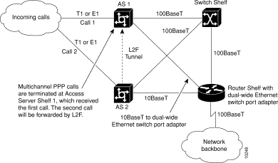
For example, in a T1 PRI configuration with 21 Access Server Shelves, the AccessPath-TS3 system has a maximum capacity of 1932 analog or single-channel ISDN calls. The maximum configuration of 21 Access Server Shelves provides a maximum capacity of 966 ISDN PRI calls. The calls are aggregated in the Switch Shelf, multiplexed, and sent over a 100BaseT Fast Ethernet connection to the Router Shelf.
Note The switch shelf is optional in AccessPath-TS3 configurations with fewer than
8 Access Server Shelves.
Figure 1-2 illustrates call pathways through the AccessPath-TS3 system.
Figure 1-2 Call Pathways Through the AccessPath-TS3 System
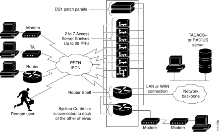
Figure 1-3 illustrates an AccessPath-TS3 system configured for 2 to 7 Access Server Shelves.
Figure 1-3 AccessPath-TS3 System Configured for 2 to 7 Access Servers
If a PPP session analog call comes in to an Access Server Shelf from the cloud, it is framed and forwarded (multiplexed) to the Switch Shelf and then forwarded to the Router Shelf.
Figure 1-4 illustrates an AccessPath-TS3 system configured for 2 to 11 Access Server Shelves.
Figure 1-4 AccessPath-TS3 System Configured for 2 to 11 Access Servers
From the Router Shelf, customers can route calls to a wide variety of services. Calls can be routed to a WAN or to another switch. If calls are forwarded through a WAN to a home gateway, they are not answered in the Router Shelf, but by the home gateway.
Figure 1-5 illustrates an AccessPath-TS3 system configured for 2 to 14 Access Servers.
Figure 1-5 AccessPath-TS3 System Configured for 2 to 14 Access Servers
Physical Specifications
The AccessPath-TS3 system includes the following components:
This section describes the physical characteristics of these components and their relationship with one another. For more information about each of these components, refer to the documents listed in the section "Related and Referenced Documents" in the preface "About This Guide."
Table 1-2 gives the physical specifications of the AccessPath-TS3 system.
Table 1-2 AccessPath-TS3 Specifications
Description
Specification
Dimensions:
With door (H x W x D)
Without door (H x W x D)
80.25 x 58.4 x 38 in. (203.8 x 58.4 x 96.5 cm)
80.25 x 23 x 36 in. (203.8 x 58.4 x 91.4 cm)
Weight
Minimum: 250 lb (113.6 kg) Maximum: 950 lb (430.9 kg)
AC Power: Input voltage, AC power supply Maximum input current
100 to 240 VAC1 7 inputs @ 15A each maximum
DC Power:
Input voltage, DC power supply Maximum input current Power dissipation
-48 to -60 VDC2 4 inputs @ 48A3 each maximum 40 to 376W4
Operating environment
32 to 104\xb0 F (0 to 40\xb0 C)
Nonoperating temperature
-4 to 149\xb0 F (-20 to 65\xb0 C)
Operating humidity
10 to 85%, noncondensing
Regulatory compliance
FCC Part 15 Class B. For additional compliance information, refer to the RegulatoryCompliance and Safety Information document that accompanied the AccessPath-TS3 system.
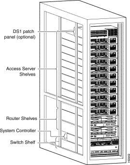
The AccessPath-TS3 system has a single EIA standard 19-in. (48.3 cm) rack cabinet that is 80.25 in. (203.9 cm) tall. Up to 576 simultaneous calls can be terminated in a single T1-configured cabinet (up to 768 in an E1-configured cabinet).
The types of interfaces are
144 to 720 modem or ISDN sessions
Up to 84 T1 or E1 PRI lines for trunk interface dial clients
The AccessPath-TS3 system also supports CT3, NxT1, and NxCT1 for dedicated connections.
Additional specifications for the individual shelves that make up the AccessPath-TS3 system are detailed in the sections that follow.
System Controller
To provide out-of-band management services, the AccessPath-TS3 system uses a System Controller (also called a Console Management Shelf). (See Figure 1-6.)
System Controller Hardware Features
The System Controller has the following hardware features:
High-performance, 100-MHz Reduced Instruction Set Computer (RISC) processor
4 slots for modules
2 slots for Personal Computer Memory Card International Association (PCMCIA) cards
Flash memory capability
4 slots for dynamic random-access memory (DRAM), user-configurable as shared memory or main (processor) memory
1 integral power supply
Supports connection to an optional external redundant power supply
High-speed console and auxiliary ports (up to 115.2 kbps)
Hardware thermal alarm to warn of excessively high operating temperature
The serial WAN connections use a proprietary, 60-pin connector. The Ethernet and Token Ring connections use standard LAN cabling with an attachment unit interface (AUI) or DB-9 connector. The console terminal provides basic and emergency local system access. The auxiliary port provides basic and emergency remote system access.
The access server uses a 68-pin connector and breakout cable, which provides 8 RJ-45 ports on each cable. These ports use RJ-45-to-DB-25 adapters to connect to asynchronous devices. Figure 1-6 shows the front panel of the System Controller.
Figure 1-6 System Controller
System Controller Specifications
Table 1-3 lists specifications of the System Controller. For more information on agency compliace, refer to the document Regulatory Compliance and Safety Information for the Cisco AccessPath-TS3 Integrated Access System.
Table 1-3 System Controller Specifications
Description
Specification
Dimensions (H x W x D)
1.75 x 17.5 x 10.56 in. (4.44 x 44.45 x 26.82 cm) (one rack unit)
Weight
10 lb (4.5 kg)
AC Power:
Input voltage, AC power supply Current Frequency Power dissipation
100 to 240VAC 2.5A 50 to 60 Hz 215W (maximum), 740 Btus1
DC Power:
Input voltage, DC power supply Current Power dissipation
40 to 72 VDC 6A 215W, 740 Btus
Network interface options
Ethernet, serial, Token Ring, BRI, (S/T and U interfaces), T1/PRI, E1/PRI
Serial interfaces
EIA/TIA2-232, EIA/TIA-449, V.35, X.21, NRZ3/NRZI, DTE/DCE4, and EIA-530 DTE. All serial interfaces use a DB-60 connector.
Console and auxiliary ports
RJ-45 connector
Operating humidity
5 to 95%, noncondensing
Operating temperature
32 to 104°F (0 to 40°C)
Nonoperating temperature
-40 to 185°F (-40 to 85°C)
Noise level
51.9 dB5 maximum
Regulatory compliance
FCC Part 15 Class B. For additional compliance information, refer to the Regulatory Compliance and Safety Information document that accompanied the AccessPath-TS3 system.
The Access Server Shelves employ a versatile data communications platform that provides the functions of an access server, a router, and digital modems in a modular chassis.
The Access Server Shelf accommodates up to three feature cards—one WAN card and one or two modem carrier cards. The choice of cards is as follows:
Quadruple T1 Primary Rate Interface (PRI) card with integrated channel service units (CSUs)
Quadruple E1 PRI card with an integrated 32-port asynchronous module
The Access Server Shelf also includes an integral AC or DC power supply and these ports:
Ethernet LAN port
Console port
Auxiliary port
The Access Server Shelf can be managed with software ranging from a simple terminal command-line interface for device configuration to an SNMP network manager. For more information about managing the Access Server Shelf using a network manager, refer to the Cisco AccessPath ManagerConfiguration Guide and the online help that is part of that software package.
Access Server Shelf Components
Each Access Server Shelf consists of the following components (see Figure 1-7):
One 19-inch modular chassis containing three feature card slots and a high-speed backplane
1 quadruple T1 or E1 card
1 Ethernet LAN port and one Fast Ethernet LAN port
1 console and one auxiliary port
1 integral power supply (AC or DC)
Figure 1-7 Access Server Shelf Front Panel
Access Server Shelf Specifications
Table 1-4 lists the specifications of the Access Server Shelf. For more information on agency compliance, refer to the document RegulatoryCompliance and Safety Information for the Cisco AccessPath-TS3 Integrated Access System.
Table 1-4 Access Server Shelf Specifications
Description
Specification
Dimensions (H x W x D)
3.5 x 17.5 x 18.25 in. (8.89 x 44.45 x 46.36 cm)
Weight
32 lb maximum (14.5 kg)
Processor
150 MHz
Operating environment
32 to 104\xb0 F (0 to 40\xb0 C)
Nonoperating temperature
-40 to 185\xb0 F (-40 to 85\xb0 C)
Operating humidity
5 to 95%, noncondensing
Noise level
70 dB @ 3 ft (0.914 m)
AC Power:
Input voltage, AC power supply Current Frequency Power factor Power dissipation
100 to 240 VAC 5A 50/60 Hz 0.80 to 0.95 460W, 1600 Btus
DC Power:
Input voltage, DC power supply Maximum input current Efficiency Power dissipation Output voltage Output voltage Output voltage Output voltage Peak output power Maximum system output power Ripple and noise Protection
-48 to -60 VDC 9.0A 63% 460W (maximum), 1600 Btus 3.3 VDC 5.0 VDC 12.0 VDC -12.0 VDC 350W 300W Under 200 mV at board level Current limit, overpower, overtemperature (latch off)
Synchronous serial interfaces (five-in-one synchronous serial WAN ports)
EIA/TIA-232, EIA/TIA-449, V.35, X.21 (NRZ/NRZI and DTE/DCE mode) EIA-530 (NRZ/NRZI and DTE mode) The five-in-one synchronous serial interface uses the DB-60 connector at the chassis.
Console and auxiliary ports
Asynchronous serial (RJ-45)
Alarm relay rating: Current Maximum switching power Maximum switching voltage
5A 150W 250 VAC, 30 VDC
Regulatory compliance
FCC Part 68. See also the Regulatory Compliance and Safety Information document that shipped with the AccessPath-TS3 system.
Router Shelf
The Router Shelf provides process server and backhaul router functionality.
Router Shelf Components
The Router Shelf comes equipped with the following components:
Dual power supplies
150-MHz network processing engine with 16-MB of DRAM
Cisco IOS software
Fast Ethernet input/output controller (MII)
Fast Ethernet port adapter
Console port
Auxiliary port
1 or 2 Cisco dual-wide Ethernet switch port adapters (optional)
Dual (redundant) power supplies (AC or DC)
The six-slot Router Shelf supports multiprotocol, multimedia routing and bridging with a wide variety of protocols and any combination of Ethernet, Fast Ethernet, and serial media.
Network interfaces reside on port adapters that provide the connection between the router's three Peripheral Component Interconnect buses and external networks. The Router Shelf has six slots for port adapters, one slot for an Input/Output (I/O) controller, and one slot for a network processing engine.
The port adapter slot configuration varies with your system configuration. (See Table 1-5.)
Table 1-5 Standard Router Shelf Port Adapter Configurations
Configuration
Shelf
Port Adapter Slot Configuration
Configuration 1
Router Shelf 1
Slot 1—Backhaul
Slot 2—Backhaul
Slot 3—Dual-wide Ethernet switch port adapter (primary)
Slot 4—Daul-wide Ethernet switch port adapter (primary)
Slot 5—Dual-wide Ethernet switch port adapter (failover)
Slot 6—Dual-wide Ethernet switch port adapter (failover)
Configuration 2
Router Shelf 1
Slot 1—Fast Ethernet
Slot 2—Backhaul
Slot 3—Backhaul
Slot 4—Blank
Slot 5—Dual-wide Ethernet switch port adapter (failover)
Slot 6—Dual-wide Ethernet switch port adapter (failover)
Configuration 3 or 4
Router Shelf 2
Slot 1—Fast Ethernet
Slot 2—Backhaul
Slot 3—Backhaul
Slot 4—Blank
Slot 5—Dual-wide Ethernet switch port adapter (failover)
Slot 6—Dual-wide Ethernet switch port adapter (failover)
There are bays for up to two AC- or DC-input power supplies. The Router Shelf operates with one power supply. A redundant power supply, which is not required, is shipped with the AccessPath-TS3 system to allow load sharing and increased system availability. The Router Shelf does not support a mixture of AC- and DC-input power.
The Router Shelf provides the following features:
Online insertion and removal (OIR)—Allows you to add, replace, or remove port adapters without interrupting the system power or entering any console commands.
Dual load-sharing power supplies that can be hot swapped—Provides system power redundancy; if one power supply or power source fails, the other one maintains system power without interruption. Also, when one power supply is powered off and removed from the router, the other one immediately meets the router's power requirements with no interruption of normal router operation.
Environmental monitoring and reporting functions—Allow you to maintain normal system operation by resolving adverse environmental conditions before loss of operation.
Downloadable software—Allows you to load new images into Flash memory remotely, you need not physically access the Router Shelf for fast, reliable upgrades.
Router Shelf Description
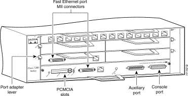
The front of the Router Shelf provides access to an I/O controller and up to six network interface port adapters. (See Figure 1-8.) The I/O controller contains the following:
A local console port for connecting a data terminal (or data terminal equipment [DTE]) and an auxiliary port for connecting a modem (or other data communications equipment [DCE]) or other devices for configuring and managing the router
2 PCMCIA slots for Flash memory cards
1 optional Fast Ethernet port
The Fast Ethernet port provides a 100-Mbps backhaul connection to the network.
Note The I/O controller is available with or without a Fast Ethernet port.
Figure 1-8 shows an I/O controller with
a Fast Ethernet port.
Figure 1-8 Router Shelf—Front View
The port adapters installed in the Router Shelf support OIR.
Note The I/O controller does not support OIR. You must power down the Router Shelf before
removing the I/O controller from the router.
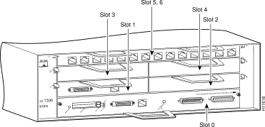
Port adapter slots in the Router Shelf are numbered from left to right and from the bottom up, beginning with port adapter slot 1 and continuing through port adapter slot 6. Port adapter slot 0 is the Fast Ethernet port on the I/O controller. (See Figure 1-9.)
Figure 1-9 Router Shelf Port Adapter Slot Numbering
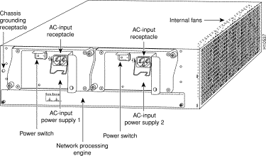
The rear of the Router Shelf provides access to the network processing engine and up to two power supplies. (See Figure 1-10.)
Figure 1-10 Router Shelf—Rear View
Note The network processing engine does not support OIR. You must power down the Router Shelf
before removing the network processing engine from the router.
The 150-MHz network processing engine has no external connectors or LEDs. There are two handles for removing and installing the network processing engine and two captive installation screws for securing it to the chassis.
Router Shelf Specifications
Table 1-6 lists the specifications and power requirements for the router shelf. For more information on agency compliance, refer to the document Regulatory Compliance and Safety Information for the Cisco AccessPath-TS3 Integrated Access System.
Table 1-6 Router Shelf Specifications
Description
Specification
Midplane
Two primary PCI buses and one secondary PCI bus with an aggregate bandwidth of 600 Mbps
Dimensions (H x W x D)
5.25 x 16.8 x 17 in. (13.34 x 42.67 x 43.18 cm)
Weight
Chassis fully configured with a network processing engine, I/O controller, 6 port adapters, 2 power supplies, and a fan tray: ~ 50 lb (22.7 kg)
Heat dissipation
370W (1262 Btu)
AC-input power
370W maximum (with either a single or dual power supply configuration)
AC-input voltage rating
100 to 240 VAC wide input with power factor correction
AC-input current rating
Not to exceed 5A maximum at 100 VAC and 2.5A maximum at 240VAC with the chassis fully configured
AC-input frequency rating
50/60 Hz
AC-input cable
18 AWG three-wire cable, with three-lead IEC-320 receptacle on the power supply end, and a country-dependent plug on the power source end
DC-output power
280W maximum (with either a single or a dual power supply configuration)
DC-input power
370W maximum (with either a single or a dual power supply configuration)
DC-input voltage rating
-48 VDC nominal in North America -60 VDC nominal in European Community
DC-input current rating
Not to exceed 13A maximum at -48 VDC (370W/-48 VDC = 7.7A typical draw) Not to exceed 8A maximum at -60 VDC (370W/-60 VDC = 6.2A typical draw)
DC voltages, supplied and maximum, steady-state current ratings
+5.2V @ 30A +12.2V @ 9A -12.0V @ 1.5A +3.5V @ 13A
DC-input cable
14 AWG (2.08 mm) recommended minimum, with at least three conductors rated for at least 140°F (60°C)--
Airflow
~80 cfm
Temperature
32 to 104°F (0 to 40°C) operating; -4 to 149°F (-20 to 65°C) nonoperating
Humidity
10 to 90% noncondensing
Agency Approvals
Safety: UL 1950, CSA 22.2 No 950, EN60950, AUSTEL TS001, AS/NZS 3260, IEC 950 EMI: FCC Class A, CSA Class A, EN60555-2, EN55022 Class B, VCCI Class 2, AS/NRZ 3548 Class A Immunity: IEC-1000-4-2, IEC-1000-4-3, IEC-1000-4-4, IEC-1000-4-5, IEC-1000-4-6, IEC-1000-4-11, IEC-1000-3-2
Switch Shelf
The Switch Shelf comes with the following components:
Dual power supplies
Supervisor Engine 100BaseTX
Fast Ethernet switching module (10BaseT/100BaseTX)
The Switch Shelf provides high-density switched Ethernet and Fast Ethernet using unshielded twisted-pair (UTP) and multimode fiber cable.
The Switch Shelf supports switched 10-Mbps Ethernet, Ethernet repeater connections, and stored and switched 100-Mbps Fast Ethernet with backbone connections to Fast Ethernet and CDDI (Copper Distributed Data Interface). Typically, Switch Shelf Ethernet interfaces connect workstations and repeaters; the Fast Ethernet interfaces connect to workstations, servers, switches, and routers.
The AccessPath-TS3 system Switch Shelf has a 1.2-Gbps media-independent switch fabric. The backplane provides the connection between power supplies, supervisor engine modules, interface modules, and the backbone module. The 1.2-Gbps media-independent fabric supports Ethernet, Fast Ethernet, and CDDI modules.
The AccessPath-TS3 system Switch Shelf supervisor engine module has the following features:
Interfacing to the 1.2-Gbps switching bus, performing at over 1 million packets per second (pps)
Bridge address table for up to 16,000 active Media Access Control (MAC) addresses and associated virtual LANs (VLANs) dynamically allocated among active ports
Switching engine that provides data path and control for all network interfaces. This includes two integrated Fast Ethernet interfaces that can support redundancy using the spanning-tree algorithm or using load sharing when used with VLANs
Fast Ethernet interfaces using RJ-45 and media-independent interface (MII) connectors or Fast Ethernet multimode fiber (MMF) or single-mode fiber (SMF) interfaces, using SC connectors (IEEE 802.3u)
Hardware support for 1024 VLANs
Dual redundant power supplies
8-MB dynamic random-access memory (DRAM) for the default system software, 4-MB Flash memory for downloading the system software, and 256-KB nonvolatile random-access memory (NVRAM) for the configuration file
Management functions that include monitoring the interface and environmental status and providing Simple Network Management Protocol (SNMP) management and the console/Telnet interface
For software feature descriptions, refer to the Cisco AccessPath-TS3 Integrated Access System Software Configuration Guide.
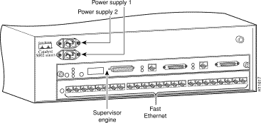
Switch Shelf Description
The AccessPath-TS3 system Switch Shelf chassis has two slots. The first slot is for the supervisor engine module, which provides switching, local and remote management, and dual Fast Ethernet interfaces. The second slot contains a Fast Ethernet module and supports 24 Fast Ethernet connections. All interfaces are accommodated in a 19-inch rack. The switch supports single or redundant AC- or DC-input power supplies.
The Switch Shelf includes a single, integrated 1.2 gigabit-per-second (Gbps) frame-based switching backplane. The media-independent backplane provides wire-speed connections for all ports. The architecture supports the following interface and network technologies:
Ethernet
Fast Ethernet
VG-AnyLAN
CDDI
Gigabit Ethernet
The backplane is the backbone module; it provides the connection between the supervisor engine module, interface modules, and power supplies. (See Figure 1-11.) Inside the chassis, the backplane slots are numbered 1 through 5, with 1 at the top of the card cage and 5 at the bottom. The Switch Shelf backplane has no active components that can fail; it is completely passive.
Figure 1-11 Switch Shelf
Switch Shelf Features
The Switch Shelf provides the following features:
Architecture and switching bus
Hardware-based switching
Hot swapping
Environmental monitoring
Module functionality
Flash memory
EEPROM
Switch Shelf Components
The Switch Shelf consists of the following components:
Supervisor engine module
Dual AC-input or DC-input power supplies
Fan assembly
Switch Shelf Specifications
Table 1-7 gives the specifications for the Catalyst 5002 switch.
Table 1-7 Switch Shelf Specifications
Description
Specification
Dimensions (H x W x D)
10.4 x 17.21 x 18.14 in. (26.4 x 43.7 x 46.1cm)
Weight
43 lb (19.5 kg) minimum 84 lb (38.1 kg) maximum
AC-input voltage
100 to 240 VAC1 wide input with power factor correction
AC-input current rating
5A2 maximum at 90 to 132 VAC 2.5A maximum at 175 to 264 VAC
14 AWG4 recommended minimum, with at least three conductors rated for at least 140\xb0 F (60\xb0 C)
Processor
25 MHz Motorola 68EC040
LAN interfaces
10BaseT Ethernet 10BaseT Ethernet (RJ-21) 10BaseT Ethernet (RJ-45) 10BaseFL Ethernet 100BaseTX Ethernet 10BaseT/100BaseTX Fast Ethernet 100BaseFX Fast Ethernet CDDI FDDI ATM LAN Emulation OC-3
Regulatory Compliance
FCC Part 15 Class B. For additional compliance information, refer to the Regulatory Compliance and Safety Information document that accompanied the AccessPath-TS3 system.