|
|

Table Of Contents
Configuring Your Cisco NAS for RADIUS
Configuring Your Cisco NAS for Lock and Key
Configuring the NAS for Remote Node IP and IPX Dial-Up
Configuring Your NAS for ISDN Dial-Up to a Cisco AS5200
Configuring the NAS for Remote Node IP Dial-Up
NAS Configuration Examples
This chapter provides examples you can apply directly to your own CiscoSecure Access Control Server (ACS). Use the information here to help you configure your CiscoSecure ACS and Cisco network access server (NAS) for the following:
•
RADIUS
•
•
•
•
Configuring Your Cisco NAS for RADIUS
Because the CiscoSecure ACS supports the RADIUS protocol, you can configure your NAS for RADIUS and achieve the same, or equivalent, security services as with the TACACS+ protocol.
The following example illustrates a typical configuration for an ISP with an existing RADIUS installation. In this sample configuration, the Cisco AS5200 can use the same authentication and accounting servers as other vendors' equipment. The result is uniform authentication, authorization, and accounting services, which in turn provides centralized user management and accounting records necessary for billing.
You can enter the following sample configuration directly into your NAS to immediately enable the CiscoSecure ACS for RADIUS-based security services:
Current configuration:!version 11.1service udp-small-serversservice tcp-small-servers!hostname isdn-14!aaa new-modelaaa authentication login default noneaaa authentication login console lineaaa authentication login secure radius localaaa authentication login vty lineaaa authentication ppp default noneaaa authentication ppp secure if-needed radius localaaa authorization exec radiusaaa authorization network radiusaaa accounting exec start-stop radiusaaa accounting network start-stop radius!username backup password radiusISdownip radius source-interface Ethernet0rlogin trusted-remoteuser-source localrlogin trusted-localuser-source radiusisdn switch-type primary-5ess!controller T1 0framing esfclock source line primarylinecode b8zspri-group timeslots 1-24!controller T1 1framing esfclock source line secondarylinecode b8zspri-group timeslots 1-24!interface Loopback0ip address 171.68.187.254 255.255.255.0!interface Ethernet0ip address 172.16.25.15 255.255.255.224!interface Serial0no ip addressshutdown!interface Serial1no ip addressshutdown!interface Serial0:23ip unnumbered Loopback0encapsulation pppisdn incoming-voice modempeer default ip address pool defaultdialer rotary-group 1dialer-group 1!interface Serial1:23ip unnumbered Loopback0encapsulation pppisdn incoming-voice modempeer default ip address pool defaultdialer rotary-group 1dialer-group 1!interface Group-Async1ip unnumbered Loopback0ip tcp header-compression passiveencapsulation pppasync mode interactivepeer default ip address pool defaultdialer-group 1ppp authentication chap pap securegroup-range 1 48!interface Dialer1ip unnumbered Loopback0encapsulation ppppeer default ip address pool defaultppp multilinkppp authentication chap pap securedialer-group 1!ip local pool default 171.68.187.1 171.68.187.48ip domain-name cisco.comip name-server 171.68.10.70no ip classlessasync-bootp dns-server 171.68.10.70!radius-server host 172.16.72.41radius-server host 172.16.72.42radius-server timeout 3radius-server key MYSECRET!dialer-list 1 protocol ip permit!line con 0login authentication consolepassword ciscoline 1 48session-timeout 15 outputautoselect during-loginautoselect ppplogin authentication securemodem InOuttransport input allline aux 0line vty 0 4login authentication vtypassword secret!endConfiguring Your Cisco NAS for Lock and Key
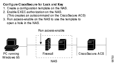
The Lock and Key Security feature, starting with Cisco IOS Release 11.1 software, offers an improved security solution: the Key Security feature (see Figure 18-1). Lock and Key security defines dynamic access control lists (ACL) that grant access per user, on a specific source/destination host basis through a user authentication process.
In essence, you can dynamically allow user access through a firewall without compromising security.
Figure 18-1 Lock and Key with CiscoSecure ACS
In a typical environment, Lock and Key security puts in place a fixed access control list (ACL) that filters all traffic except for Telnet traffic until a remote user has been authenticated with the security mechanism.
When a user logs in and successfully authenticates with the CiscoSecure ACS, the ACS issues the access-enable command to the NAS, which confirms that the user is on an ACL and activates a configuration template that alters the ACL for the incoming interface to enable the privileges allowed to the authenticated user.
After authentication, a specific ACL is put in place, for the Telnet port only, that allows the authenticating of user/network access beyond the firewall.
Caution
You can enter the following sample configuration to immediately enable Lock and Key with the CiscoSecure ACS. This configuration enables Lock and Key functionality on a Cisco 2511. Depending on your NAS and network topology, you might have to modify the configuration slightly to meet your exact needs.
NAS "delta" configuration=========================! simple tacacs+ configuration. You need EXEC authorization to execute! the autocommand configured for the user!aaa new-modelaaa authentication login default tacacs+aaa authorization exec tacacs+!tacacs-server host 10.10.1.200tacacs-server key secret!! Now configure the access-list. The fixed access list should deny! traffic except for telnet to the router itself and deny everything! else. The dynamic part of the access-list determines what access! the user will have after they have authenticated themselves. In! this case, the user will have full IP access after authentication.!access-list 101 permit tcp any host 10.10.1.254 eq telnetaccess-list 101 dynamic temp permit ip any any!! Now apply the access-list inbound to the dial-up interfaces!int s0:23ip access-group 101 inCiscoSecure database================# match keys with the NASkey = "secret"# definition of the lock&key useruser = unlockme {# his LOGIN passwordpassword = clear "key"# define user's EXEC authorization profileservice = exec {# this will unlock the access-list for# the user for 15 minutesset autocmd = "access-enable 15"}}Full NAS configuration======================DEMO1#wr tBuilding configuration...Current configuration:!version 11.1service udp-small-serversservice tcp-small-servers!hostname Router!aaa new-modelaaa authentication login default tacacs+aaa authorization exec tacacs+!interface Ethernet0ip address 10.10.1.254 255.255.255.0!interface Serial0:23ip address 10.10.2.254 255.255.255.0ip access-group 101 inencapsulation pppdialer map ip 10.10.2.1 name cisco-1004 broadcastdialer-group 1ppp authentication chap!access-list 101 permit tcp any host 10.10.2.254 eq telnetaccess-list 101 dynamic temp permit ip any anytacacs-server host 10.10.1.200tacacs-server key secret!line con 0line aux 0line vty 0 4!endConfiguring the NAS for Remote Node IP and IPX Dial-Up
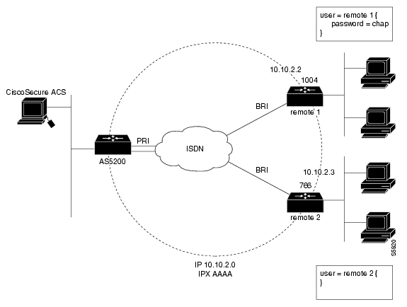
In this next example (see Figure 18-2), a remote node dials in to a NAS, authenticates by means of the CiscoSecure ACS, and is authorized on a protected IPX network.
Figure 18-2 Address Scheme for Routers Dialing in to the Cisco AS5200
You can enter the following sample configuration directly into your NAS to immediately enable the CiscoSecure ACS for remote node IP and IPX dial-up. Depending on your NAS and network topology, you might have to adapt this sample configuration slightly to meet your system's needs.
Remote Node IP and IPX Dial-Up Configuration:!version 11.1service udp-small-serversservice tcp-small-servers!hostname AS5200!aaa new-modelaaa authentication login default tacacs+ enableaaa authentication ppp default if-needed tacacs+aaa authorization execaaa authorization networkaaa accounting exec start-stop tacacs+aaa accounting network start-stop tacacs+!isdn switch-type primary-5ess!ipx routing!controller T1 0framing esfclock source line primarylinecode b8zspri-group timeslots 1-24!controller T1 1framing esfclock source line secondarylinecode b8zspri-group timeslots 1-24!interface Loopback0ip address 10.10.2.254 255.255.255.0ipx network AAAAipx sap-interval 0!interface Ethernet0ip address 10.10.1.254 255.255.255.0ipx network BBBB!interface Serial0no ip addressshutdown!interface Serial1no ip addressshutdown!interface Serial0:23ip unnumbered Loopback0encapsulation pppisdn incoming-voice modemipx ppp-client Loopback0peer default ip address pool defaultdialer rotary-group 1dialer-group 1!interface Serial1:23ip unnumbered Loopback0encapsulation pppisdn incoming-voice modemipx ppp-client Loopback0peer default ip address pool defaultdialer rotary-group 1dialer-group 1!interface Group-Async1ip unnumbered Loopback0ip tcp header-compression passiveencapsulation pppasync mode interactiveipx ppp-client Loopback0peer default ip address pool defaultdialer-group 1no cdp enableppp authentication chap papgroup-range 1 48!interface Dialer1ip unnumbered Loopback0encapsulation pppipx ppp-client Loopback0peer default ip address pool defaultdialer-group 1ppp multilinkppp authentication chap pap!tacacs-server host 10.10.1.200tacacs-server key secretip local pool default 10.10.2.1 10.10.2.48!ipx router ripno network AAAA!dialer-list 1 protocol ip permitdialer-list 1 protocol ipx permit!line con 0line 1 48autoselect during-loginautoselect ppplogin localmodem InOutmodem autoconfigure type microcom_hdmstransport input allstopbits 1rxspeed 115200txspeed 115200flowcontrol hardwareline aux 0line vty 0 4!endConfiguring Your NAS for ISDN Dial-Up to a Cisco AS5200
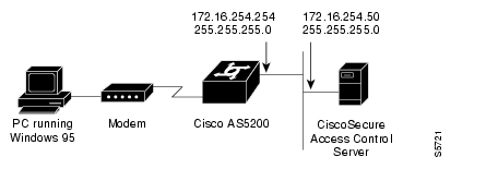
You can enter the following sample configuration directly into your NAS to immediately enable CiscoSecure ACS for ISDN dial-up to a Cisco AS5200. (See Figure 18-3.)
Figure 18-3
ISDN Dial-Up to a Cisco AS5200
Depending on your NAS and network topology, you might have to adapt this sample configuration slightly to meet your system's needs.
Current configuration:!version 11.1service udp-small-serversservice tcp-small-servers!hostname AS5200!aaa new-modelaaa authentication login default tacacs+ enableaaa authentication ppp default if-needed tacacs+aaa authorization execaaa authorization networkaaa accounting exec start-stop tacacs+aaa accounting network start-stop tacacs+!isdn switch-type primary-5ess!ipx routing!controller T1 0framing esfclock source line primarylinecode b8zspri-group timeslots 1-24!controller T1 1framing esfclock source line secondarylinecode b8zspri-group timeslots 1-24!interface Loopback0ip address 10.10.2.254 255.255.255.0ipx network AAAAipx sap-interval 0!interface Ethernet0ip address 10.10.1.254 255.255.255.0ipx network BBBB!interface Serial0no ip addressshutdown!interface Serial1no ip addressshutdown!interface Serial0:23ip unnumbered Loopback0encapsulation pppisdn incoming-voice modemipx ppp-client Loopback0peer default ip address pool defaultdialer rotary-group 1dialer-group 1!interface Serial1:23ip unnumbered Loopback0encapsulation pppisdn incoming-voice modemipx ppp-client Loopback0peer default ip address pool defaultdialer rotary-group 1dialer-group 1!interface Group-Async1ip unnumbered Loopback0ip tcp header-compression passiveencapsulation pppasync mode interactiveipx ppp-client Loopback0peer default ip address pool defaultdialer-group 1no cdp enableppp authentication chap papgroup-range 1 48!interface Dialer1ip unnumbered Loopback0encapsulation pppipx ppp-client Loopback0peer default ip address pool defaultdialer-group 1ppp multilinkppp authentication chap pap!tacacs-server host 10.10.1.200tacacs-server key secretip local pool default 10.10.2.1 10.10.2.48!ipx router ripno network AAAA!dialer-list 1 protocol ip permitdialer-list 1 protocol ipx permit!line con 0line 1 48autoselect during-loginautoselect ppplogin localmodem InOutmodem autoconfigure type microcom_hdmstransport input allstopbits 1rxspeed 115200txspeed 115200flowcontrol hardwareline aux 0line vty 0 4!endConfiguring the NAS for Remote Node IP Dial-Up
You can enter the following sample configuration directly into your NAS to immediately enable the CiscoSecure ACS for remote node IP dial-up. (See Figure 18-4.)
Figure 18-4 Remote Node IP Dial-Up
Depending on your NAS and network topology, you might have to adapt this sample configuration slightly to meet your system's needs.
Current configuration:!version 11.1service udp-small-serversservice tcp-small-servers!hostname AS5200!aaa new-modelaaa authentication login default tacacs+ enableaaa authentication ppp default if-needed tacacs+aaa authorization execaaa authorization networkaaa accounting exec start-stop tacacs+aaa accounting network start-stop tacacs+!isdn switch-type primary-5ess!controller T1 0framing esfclock source line primarylinecode b8zspri-group timeslots 1-24!controller T1 1framing esfclock source line secondarylinecode b8zspri-group timeslots 1-24!interface Ethernet0ip address 10.10.1.254 255.255.255.0!interface Serial0no ip addressshutdown!interface Serial1no ip addressshutdown!interface Serial0:23ip unnumbered Ethernet0encapsulation pppisdn incoming-voice modempeer default ip address pool defaultdialer rotary-group 1dialer-group 1!interface Serial1:23ip unnumbered Ethernet0encapsulation pppisdn incoming-voice modempeer default ip address pool defaultdialer rotary-group 1dialer-group 1!interface Group-Async1ip unnumbered Ethernet0ip tcp header-compression passiveencapsulation pppasync mode interactivepeer default ip address pool defaultdialer-group 1no cdp enableppp authentication chap papgroup-range 1 48!interface Dialer1ip unnumbered Ethernet0encapsulation ppppeer default ip address pool defaultdialer-group 1ppp multilinkppp authentication chap pap!tacacs-server host 10.10.1.200tacacs-server key secretip local pool default 10.10.1.1 10.10.1.48!dialer-list 1 protocol ip permit!line con 0exec-timeout 0 0line 1 48autoselect during-loginautoselect ppplogin localmodem InOutmodem autoconfigure type microcom_hdmstransport input allstopbits 1rxspeed 115200txspeed 115200flowcontrol hardwareline aux 0line vty 0 4!end
![]()
![]()
![]()
![]()
![]()
![]()
![]()
![]()
Posted: Wed Feb 16 10:26:00 PST 2005
All contents are Copyright © 1992--2005 Cisco Systems, Inc. All rights reserved.
Important Notices and Privacy Statement.