|
|

Cisco Part Numbers: STS-10x and STS-10
This publication describes the procedure for replacing or upgrading EPROMs in the Cisco STS-10x and the earlier STS-10 Terminal Server models. System Software Release 8.2 requires 1-Megabit EPROMs; System Software Release 8.3 requires 2-Megabit EPROMs and a jumper change.
 | Caution The procedures described in this publication should be performed by qualified service personnel only. |
Follow the guidelines in the section, "Preventing Electrostatic Discharge (ESD) Damage."
The following tools are required to replace EPROMs on the STS-10x and STS-10 Terminal Server system cards.
Cisco has distributed two versions each of the STS-10x and the STS-10 systems. Look carefully at the illustrations of each card in this publication to identify your system's version. The card illustrations show the correct location and labeling of the EPROMs to be replaced. Note that some STS-10x systems might be labeled STS-10.
STS-10x and the STS-10 system cards have two system software EPROMs. The EPROM locations vary according to the generation of system card. Use Figure 1 through Figure 4 to determine which generation of STS-10 Terminal Server you have.
To replace the system EPROMs you will need to do the following:
If you are upgrading STS-10x models with Release 8.3 (2-Megabit) EPROMs, you will also need to do the following:
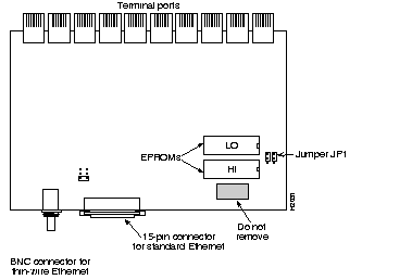
On the fourth generation version of the STS-10x system card (as shown in Figure 1), replace the two system EPROMs labeled HI and LO. Match the label on the EPROM with the label on the card before inserting a new EPROM, putting each replacement EPROM in the corresponding socket of the EPROM being replaced.
.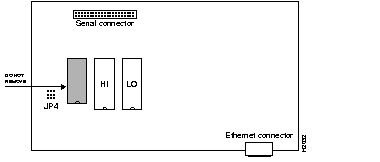
On the third generation version of the STS-10x system card (as shown in Figure 2), replace the two system EPROMs labeled HI and LO. Match the label on the EPROM with the label on the card before inserting a new EPROM, putting each replacement EPROM in the corresponding socket of the EPROM being replaced.
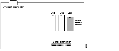
On the second generation version of the STS-10 system card (as shown in Figure 3), the two system EPROMS are labeled U41 and U42. Match the label on the EPROM with the label on the card before inserting a new EPROM, putting each replacement EPROM in the corresponding socket of the EPROM being replaced.
.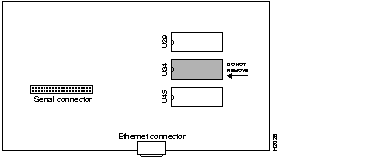
On the first generation version of the STS-10 system card (as shown in Figure 4), the two system software EPROMs are labeled U29 and U45. Match the label on the EPROM with the label on the card before inserting a new EPROM, putting each replacement EPROM in the corresponding socket of the EPROM being replaced.
To ensure general safety, follow these guidelines:
 | Warning Metal objects will heat up when connected to power and ground. This heated metal can cause serious burns or can weld to a terminal. |
When working on equipment powered by electricity, follow these guidelines:
When electronic printed circuit cards are improperly handled, the resulting electrostatic discharge (ESD) can damage equipment and impair electrical circuitry and can result in complete or intermittent failures.
Always follow ESD prevention procedures when removing and replacing cards. Wear an ESD wrist strap, ensuring that it makes good skin contact. To safely channel unwanted ESD voltages to ground, connect the clip to an unpainted chassis frame surface. To properly guard against ESD damage and shocks, the wrist strap and cord must operate effectively. To ensure that the resistor is providing proper ESD protection, use an ohmmeter to check the ESD wrist strap periodically .
If no wrist strap is available, ground yourself by touching the metal part of the chassis prior to the procedure.
 | Caution Read through this document before starting the EPROM replacement procedure. Before beginning any procedures, turn off power to the system and unplug the power cord. |
Follow these steps to replace the EPROMs in a fourth generation STS-10x terminal server.
 | Caution Before beginning the EPROM replacement procedure, review the section, "General Safety." |
Step 1: Turn off power to the server and unplug the power cord from the wall receptacle.
Step 2: Turn the STS-10x upside down. Loosen and remove the two screws that secure the bottom cover and the single screw on the rear panel (as shown in Figure 5).
Step 3: Lift the bottom panel off the chassis.
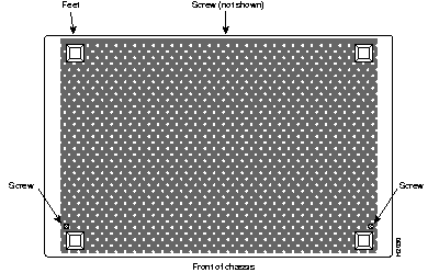
Step 4: Slip on an ESD wrist strap, ensuring that it makes good contact with your skin. Connect the equipment end of the wrist strap to an unpainted surface of the chassis, preferably on the inside of the chassis back panel. If you are using a strap with an alligator-type clip, connect the clip to an unpainted area on the chassis or to another proper grounding point or surface.
Step 5: On the system card, locate the EPROMs marked HI and LO (shown in Figure 1). Use an EPROM extractor to carefully remove the EPROMs from their sockets. If an EPROM extractor is not available, use the tip of a flatblade screwdriver to gently rock the EPROMs out of their sockets.
Step 6: To insert the new EPROMs, align the EPROM notch with the notch in the socket. Figure 1 shows the correct orientation of the EPROMs.
 | Caution When inserting the EPROMs, be very careful not to bend or crush any of their pins. If any pins are bent, use needle-nosed pliers to straighten them out. |
Step 1: Locate jumper array JP1, shown in Figure 1 and in Figure 6. Note the position of the jumpers. If the software version you are replacing is prior to Release 8.3, the jumpers will be set as shown in Figure 6, as viewed from the rear of the chassis, looking toward the front.

Step 2: Move the right jumper up one post, so it is flush with the left jumper, as shown in Figure 6.
Step 3: When both new EPROMs are installed, and the jumper in JP 1 is set properly, replace the bottom cover and turn the STS-10x right side up.
Step 4: Turn on the power to check out the installation.
If you power up a system when one or more of the EPROMs is inserted incorrectly, the system will not boot properly. If this happens, do the following:
Step 1: Open the chassis.
Step 2: Locate the bent EPROM pin, straighten it, then carefully re-insert it.
Step 3: Replace the bottom panel and the chassis cover screw, then turn on the power to check out the installation again.
When the STS-10x tests successfully, replace the remaining chassis screws.
Follow these steps to replace the EPROMs in the earlier Cisco STS-10x or STS-10 terminal server system card.
Step 1: Turn off power to the server.
Step 2: Access the system card following these steps:
Step 3: Consult Figure 2, Figure 3, and Figure 4 to determine which generation of the STS-10 you have, and the location of the EPROMs you will be changing.
Step 4: Use the EPROM extractor to gently lift out the EPROMs from their sockets.
Step 5: To insert an EPROM into its socket, align the EPROM notch with the notch in the socket and press it in. If the EPROM is shorter than its socket, insert pins starting with the sockets farthest from the notch and allow the extra space to fall between the notches.
 | Caution When inserting the EPROMs, be careful not to bend or crush any of the pins. If this happens, use needle-nosed pliers to straighten the pins out. |
Step 6: For STS-10x third generation upgrades to Release 8.3, locate the jumper array JP4, shown in Figure 6. Note the position of the jumpers. If the software version you are replacing is prior to Release 8.3, the jumpers will be set as shown in Figure 6. The jumper settings are shown as viewed from the rear of the chassis, looking toward the front.

Step 7: For STS-10x third generation upgrades to Release 8.3, move the bottom jumper over one post, so it is flush with the right jumper, as shown in Figure 6.
Step 8: When both new EPROMs are installed and the jumper in JP 4 is set properly, replace the bottom cover and turn the STS-10x right side up (do not re-install the screws yet).
Step 9: When both EPROMs have been replaced, reconnect the serial ribbon cable (if necessary), close the cover, and replace the screws securing the back cover.
Step 10: Turn on power and test the installation.
If you power up a system when one or more of the EPROMs is inserted incorrectly, the system will not boot properly. If this happens, do the following:
Step 1: Open the chassis again.
Step 2: Locate the bent EPROM pin, straighten it, then carefully re-insert it.
Step 3: Replace the bottom panel and the chassis cover screw, then turn on the power to check out the installation again.
When the STS-10x tests successfully, replace the remaining cover screws.
STS-10x and STS-10 are trademarks of Cisco Systems, Inc.
Copyright © 1992, Cisco Systems, Inc.
All rights reserved. Printed in USA.
|
|