|
|

This section describes the procedure for upgrading the system software by replacing the EPROMs on the system card. To perform the upgrade, you will:
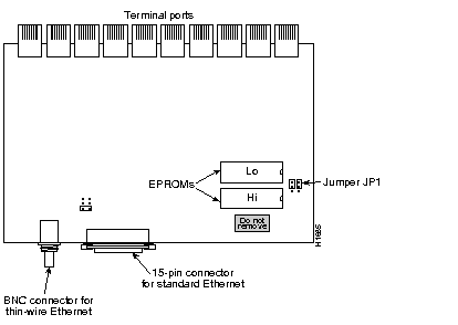
The system card, and the location of the EPROMs and jumpers, are shown in Figure 4-1 .

The following tools are required for this procedure:
 | Caution Before beginning the EPROM replacement procedure, review the "Safety" section in Chapter 2. |
Step 1: Turn off power to the server, and unplug the power cord from the wall receptacle.
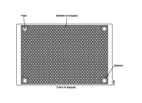
Step 2: Locate and remove the chassis cover screw on the back of the STS-10x, shown in Figure 4-2.
Step 3: Turn the STS-10x upside down. Loosen and remove the three screws that secure the bottom cover: a single screw on the rear panel, and two on the bottom. Lift the bottom panel off the chassis. 
Step 4: Slip on an ESD wrist strap, and ensure that it makes good contact with your skin. Connect the equipment end of the wrist strap to an unpainted surface of the chassis, preferably on the inside of the chassis back panel. If you are using a strap with an alligator-type clip, connect the clip to an unpainted area on the chassis or other proper grounding point or surface.
Step 5: On the system card, locate the EPROMs shown in Figure 4-1 .
Step 6: Use a chip extractor to carefully remove the EPROMs from their sockets. If a chip extractor is not available, use the tip of a flatblade screwdriver to gently rock them out of the sockets.
Step 7: To insert the new EPROMs, align the EPROM notch with the notch in the socket. Figure 4-1 illustrates the correct orientation of the EPROMs.
 | Caution When inserting the EPROMs, be very careful not to bend or crush any of its pins. If this happens, use needle-nosed pliers to straighten them out. |
Step 8: Locate jumper array JP1, shown in Figure 4-1 . Note the position of the jumpers. If the software version you are replacing is prior to release 8.3, the jumpers will be set as shown in Figure 4-3. The jumper settings are shown as viewed from the rear of the chassis, looking toward the front.

Step 9: Move the right jumper up one post, so it is flush with the left jumper, as shown in Figure 4-3.
Step 10: When both new EPROMs are installed and the jumper in JP4 is set properly, replace the bottom cover and turn the STS-10x rightside-up (do not re-install the screw yet).
Step 11: Turn on the power to check out the installation.
If you power up a system when one or both of the EPROMs is incorrectly inserted, the system may either halt operation, or may print a message on the console port reporting a checksum error. When this happens, do the following:
Step 1: Open the chassis again, as described in steps 3 and 4.
Step 2: Locate the offending EPROM pin, straighten it, then carefully re-insert it.
Step 3: Replace the bottom panel and the chassis cover screw, then turn on the power to check out the installation again.
When the STS-10x tests successfully, replace the remaining cover screws.
|
|