|
|

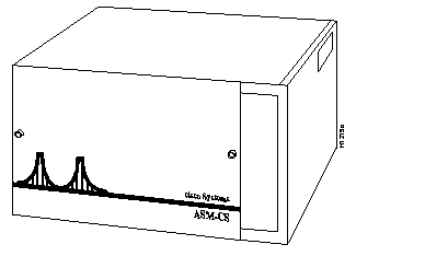
The ASM-CS is a modular communication server chassis incorporating a nine-slot multibus backplane, which can accommodate up to nine separate interface and controller cards. Figure 1-1 shows the front of the ASM-CS chassis.

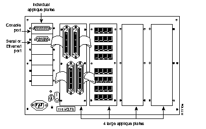
The ASM-CS can support one Ethernet, synchronous serial, or Token Ring network interface for external network connection, and up to 112 asynchronous serial connections. The external connection to the network is provided by an interface applique attached to the rear of the ASM-CS (see Figure 1-2) and is discussed in detail in Appendix A, "Cabling Specifications," which includes pinouts of all of the different types of interface appliques and cables.

Your responsibilities for bringing the ASM-CS on line will include making the external connections to the various networks by way of the appropriate interface cables and using the configuration software routines specified in the appropriate Getting Started Guide and associated companion documentation included with this manual.
The ASM-CS is a communication server that connects asynchronous devices to any local or wide area network that uses TCP/IP, LAT, or SLIP. All communication servers can be configured to interface with Ethernet local area networks (LANs). Additionally, the ASM-CS can be configured to support Token Ring LANs or synchronous serial network connections. The ASM-CS chassis is identified by its size, capacity, physical characteristics, components, and configuration.
Table 1-1 provides a summary of the physical characteristics of the ASM-CS.
Table 1-2 describes the power and cooling specifications for the ASM-CS.
| Description | Specifications |
|---|---|
| Power dissipation | 350 watts (1193.5 Btu1/hour) |
| Input voltage | 110 VAC model MAS-11 or the 240VAC model MAS-11B
220/240 VAC (U.K. model MAS-26) |
| Frequency | 47 to 63 Hz |
| Current rating | 5 amp @ 110 V; 2.5 amp @ 220 V |
| Current and DC voltages available | U.S. 35 amp @ +5 V; 4 amp @ +12 V
1.5 amp @ -5 V; 1.5 amp @ -12 V |
| U.K. 30 amp @ +5 V; 7 amp @ +12 V
5 amp @ -12 V; 1 amp @ -5 V | |
| Cooling | One 160 CFM2 blower and exhaust vent |
This section provides an overview of the printed circuit processor and interface cards that can be used in the ASM-CS. Included are the following three types:
The combination of network interface cards in an ASM-CS determines its operation. The various cards in each category are described in the following sections.
The processor card contains and executes most of the programs that control the system. Table 1-3 lists the specifications for the central processing units used in the ASM-CS.
Memory cards provide long-term, nonvolatile random-access memory (NVRAM) storage for configuration and data. Table 1-4 lists the memory cards available for the ASM-CS.
Network interface cards connect your ASM-CS to one or more networks. Table 1-5 describes the various network interface cards available for the ASM-CS.
Table 1-6 provides a listing of the card and port types and the number of each that can be installed in the ASM-CS.
| No. of Cards1 | Card Name | Card Type | Max. No. of Ports |
|---|---|---|---|
| 1 | CSC/3 or CSC/4 | Processor | 1 Console 1 Auxiliary |
| 1 | CSC-MCI | Ethernet
or serial | 1
1 |
| 1 | CSC-1R | Token Ring | 1 |
| 1 | CSC-R16M | Token Ring | 1 |
External network connections to the ASM-CS are provided through a variety of rear-panel connector plates and appliques.
Table 1-7 lists the four types of asynchronous serial appliques available for the ASM-CS.
| Product Name | Applique Type and Quantity1 | Quantity of Ports2 |
|---|---|---|
| APP-LTA | Two 50-pin telco female connectors | 16 ports |
| APP-LTB | Four 50-pin telco female connectors | 32 ports |
| APP-LRA | Sixteen RJ-11 female connectors | 16 ports |
| APP-LRB | Thirty-two RJ-11 female connectors | 32 ports |
Table 1-8 provides a listing of the available connector plates, their relative sizes, the number of appliques per plate, and where the appliques can be positioned on the rear panel of the chassis. This listing assumes that the maximum number of asynchronous connections are installed (112), requiring all four long plates, and that the network interface applique is therefore confined to one of the individual plates below the console port on the left side of the rear panel (with the rear panel of the chassis facing you).
| Interface Type | Individual Connector Plates |
|---|---|
| Token Ring | 5 |
| Ethernet | 5 |
| 10BaseT | 4 |
| RS-232 (and NRZI) | 4 |
| RS-449 | Requires a long plate1 |
| V.35 high density | 4 |
| X.21 | 4 |
| G.703 | 4 |
| Asynchronous serial | Require long plates |
|
|