cc/td/doc/product/access/acs_serv
hometocprevnextglossaryfeedbacksearchhelp
PDF

Table of Contents

Read Me First
Cisco AS5800 Universal Access Server

1   Introduction
2   Unpack and Install Your Hardware
3   Complete the Hardware Installation Checklist
4   Configure Your Software

Read Me First
Cisco AS5800 Universal Access Server


Introduction

Unpack and Install Your Hardware

Complete the Hardware Installation Checklist

Configure Your Software

1   Introduction

This document contains information about your Cisco AS5800 universal access server. It provides an overview of procedures you should follow when unpacking and installing your access server for the first time.

This document helps you locate the various system components, and provides a list of shipping carton contents. It explains how to unpack your shipping cartons and refers you to the appropriate documentation for installing system hardware and software. This document also contains an installation checklist.

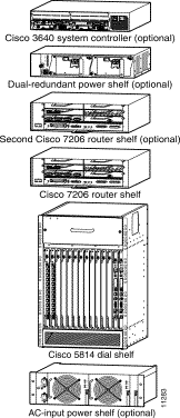
Your Cisco AS5800 universal access server includes the following components:

You may also wish to order a Cisco 3640 system controller. Another optional addition is a second Cisco 7206 router shelf and dial shelf controller card if you wish to use a split dial shelf configuration.

The basic procedure for setting up your system is as follows:

1. Unpack and install your hardware in the following order:

    (a). Unpack and Install Your AC-Input Power Shelf (Optional)

    (b). Unpack and Install Your Cisco 5814 Dial Shelf

    (c). Unpack and Install Your Cisco 7206 Router Shelf

2. Complete the "Hardware Installation Checklist"

3. Configure your software

4. The following documents are to be referenced in the order listed:

    (a). Cisco AS5800 Universal Access Server Hardware Installation Guide.

    (b). Cisco AS5800 Universal Access Server Operations, Administration, Maintenance, and Provisioning Guide

2   Unpack and Install Your Hardware

This section describes the procedures for unpacking and installing your Cisco AS5800 universal access server main chassis components, as shown in Figure 1. All components are intended to be rack-mounted in the arrangement shown, from bottom to top. If you are using the AC-input power shelf, we recommend that you do the following to rack-mount the AC input power shelf:


Step 1   Remove the power supplies from the AC-input power shelf chassis

Step 2   Connect the cables to the power supply only

Step 3   Rack mount the AC-input power shelf

Step 4   Install the power supplies removed earlier

If you are not using the AC-input power shelf, proceed to the section "Unpack and Install Your Cisco 5814 Dial Shelf."

Figure 1—System Components


Unpack and Install Your AC-Input Power Shelf (Optional)


The optional AC-input power shelf, which includes two 2,000W AC-input power supplies, weighs approximately 50 pounds (22.7 kg). Use lifting safety precautions when moving the carton and lifting the chassis.

Step 1   Locate the AC-input power shelf carton.

Step 2   Unpack the carton and verify receipt of all components, as listed in Table 1.

Step 3   Install your AC-input power shelf in the rack using the rack-mounting and cabling instructions in the Cisco AS5800 Universal Access Server Hardware Installation Guide.

Step 4   Proceed to the section "Unpack and Install Your Cisco 5814 Dial Shelf."

Table 1—AC-Input Power Shelf Component Checklist

Component

___

AC-input power shelf with 2 AC-input power supplies


___

___

___

___

Power cables:

  • 2 AC power cords
  • 2 DC interconnect cables
  • 1 monitor cable (DB-25 to DB-9)
  • 1 double lug ground cable


___

Documentation:

  • Cisco AS5800 Universal Access Server Hardware Installation Guide


Note:      If anything is missing from your order, contact your service representative.


Unpack and Install Your Cisco 5814 Dial Shelf


The Cisco 5814 dial shelf weighs approximately 278 pounds (22.7 kg) when fully loaded. Use lifting safety precautions when moving the carton and lifting the chassis. Unless you are using a forklift, do not attempt to move the dial shelf without the blower assembly, dial shelf cards, DC power entry modules, and dial shelf controller card(s) removed from the dial shelf chassis. To perform these tasks, refer to the preinstallation chapter in the Cisco AS5800 Universal Access Server Hardware Installation Guide.

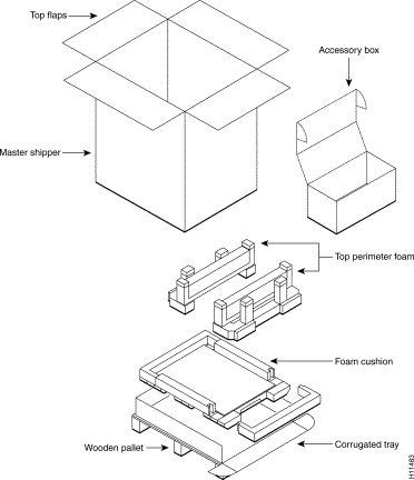
Your Cisco 5814 dial shelf carton consists of a master shipper (a bottomless corrugated sleeve with top flaps), an accessory box, a top perimeter foam piece, a plastic bag, and a base tray assembly (corrugated tray, foam cushions, corrugated chassis platform) and wooden pallet. See Figure 2 for packaging identification.

Unpacking Guidelines

Observe the following guidelines when unpacking and preparing to install your Cisco AS5800 universal access server:dial shelf

  • The dial shelf chassis is not intended to be moved frequently. Before you unpack and install your Cisco 5814 dial shelf, ensure your site is properly prepared so you can avoid the need to move the dial shelf to accommodate power sources and network connections.
  • Before moving the chassis to a permanent site, we recommend that you review the site safety and environmental considerations provided in the Cisco AS5800 Universal Access Server Hardware Installation Guide.
  • Ensure that you have adequate clearance through doors and passages. The shipping container measures 39 x 24.5 x 30 inches (99 x 62.2 x 76.2 cm).
  • Use a hand cart, pallet jack, or forklift to move the unpacked chassis carton to another location. A fully configured dial shelf weighs approximately 278 pounds (126.1 kg).
  • Ensure that you have sufficient room to unpack the dial shelf.
  • Do not destroy the shipping containers. Flatten and store them with the pallet. Use these containers to either transport the dial shelf, or return it to the factory (if necessary).

Figure 2—Cisco 5814 Dial Shelf Packaging Detail


Unpacking Procedure

Use the following procedure for unpacking the Cisco 5814 dial shelf. Refer to Figure 2 where applicable.


Step 1   Use a hand cart, pallet jack, or forklift to place the carton as near to the installation location as possible.

Step 2   Remove the bands around the carton exterior and open the top flaps. (Bands are not reusable.)

Step 3   Remove the accessory box and set it aside. The accessory box contains the documentation, cables, and rack-mount hardware you need to complete this installation.

Step 4   Lift the master shipper over the top of the chassis and set it aside.

Step 5   Remove the top perimeter foam and set it aside.

Step 6   Remove the plastic bag from the chassis.

Step 7   Verify you have received all components listed in Table 2.

Step 8   Remove the blower assembly, dial shelf cards, DC power entry modules, and dial shelf controller card(s) from the dial shelf chassis before lifting the dial shelf chassis off the pallet. To perform these tasks, refer to the preinstallation chapter in the Cisco AS5800 Universal Access Server Hardware Installation Guide.

Step 9   Roll down the front of the corrugated base tray for easier chassis removal.

Step 10   Install your dial shelf in a rack using the rack-mounting and cabling instructions in the Cisco AS5800 Universal Access Server Hardware Installation Guide.

Step 11   Proceed to the section "Unpack and Install Your Cisco 7206 Router Shelf."


Note:      We recommend that you retain the shipping containers for future use; however, you can order replacement packaging (PKG-5814=) for the Cisco 5814 dial shelf.


Table 2—Cisco 5814 Dial Shelf Component Checklist

Component

___

Dial shelf chassis


___

___

___

___

___

___

___

Installed components:

  • Dial shelf controller card (with 2 PCMCIA Flash memory cards)
  • Dial shelf trunk card(s)—as per configuration
  • Dial shelf cards—up to 10 cards maximum
  • Blank filler cards to fill all empty dial shelf slots
  • 2 DC power entry modules (PEMs)
  • Blower assembly
  • Filter module


___

Cables:

  • Ingress trunk cables (as specified in order)


___

Rack-mount kit (included in accessory kit):

  • 6-bracket kit for standard 19-inch or telco rack and M5 x 10-mm Phillips flathead screws


___

___

___

___

___

___

___


Documentation (included in accessory kit):

  • Read Me First document (on shipping container exterior)
  • Cisco AS5800 Universal Access Server Hardware Installation Guide
  • Cisco AS5800 Universal Access Server Operations, Administration, Maintenance, and Provisioning Guide
  • Cisco AS5800 Universal Access Server Regulatory Compliance and Safety Information
  • Spare component installation and configuration notes, when applicable
  • Documentation CD-ROM package
  • Cisco Information Packet—for license and warranty information, and service and support information

Note:      If anything is missing from your order, contact your service representative.


Unpack and Install Your Cisco 7206 Router Shelf

Your Cisco 7206 router shelf is fully configured to include a network processor card, I/O controller card, dial shelf interconnect port adapter, and other network port adapters.


Your Cisco 7206 router shelf chassis, when fully configured, weighs approximately 50 pounds (22.7 kg). Use lifting safety precautions when moving the carton and lifting the chassis.

Step 1   Locate the Cisco 7206 router shelf carton. Unpack the carton and verify receipt of all ordered components.

Step 2   Install your router shelf in the rack using the rack-mounting and cabling instructions in the Cisco 7206 Installation and Configuration Guide.

Step 3   Install your Dial Shelf Interconnect port adapter (if not already installed) and connect the proprietary cable using the Cisco AS5800 Universal Access Operation, Administration, Maintenance, and Provisioning (OAM&P) Guide.


Note:      In a typical rack-mount configuration, both the dial shelf and router shelf are mounted together in a rack, with the router shelf stacked directly above the dial shelf. Although we do not recommend that the dial shelf be separated from the router shelf, a 20-foot interconnect cable is available if you need to install the router shelf in an adjacent rack.


Step 4   Configure the AS5800 universal access server and Cisco 3640 system controller software using the procedures described in the Cisco AS5800 Universal Access Server Operations, Administration, Maintenance, and Provisioning Guide.

Table 3—Cisco 7206 Router Shelf Component Checklist

 Component


Router shelf chassis


___

___

___

___

___

___

___

___

Installed components:

  • Dial shelf interconnect adapter(s)—up to 2
  • Network processor card (NPE-200 or larger)
  • I/O controller card
  • 2 AC-input or DC-input power supplies (depending on your configuration)
  • Port adapters—up to 5
  • Blank port adapters to fill all empty port adapter slots
  • Dial shelf interconnect cable(s)—up to 2 (8 ft or 20 ft)
  • Flash memory card(s)—up to 2


___

___

Rack-mount/cable-management kit:

  • Brackets for standard 19-inch or telco rack and M3 x 8-mm Phillips flathead screws
  • Cable-management brackets, M4 x 8-mm Phillips flathead screws, and 10-32 x 3/8-inch slotted binderhead screws

___

___

Power cables:

  • 2 AC or DC power cables (depending on your configuration)


___

___

___

___


___

___

___


Documentation:

  • Cisco 7206 Installation and Configuration Guide—used in conjunction with the Cisco AS5800 Universal Access Server Hardware Installation Guide to support all router shelf hardware information
  • Quick Reference Card
  • Regulatory Compliance and Safety Information
  • Port adapter installation and configuration notes, when applicable
  • Documentation CD-ROM package
  • Cisco Information Packet—for license and warranty information, and service and support information

Note:      If anything is missing from your order, contact your service representative.


3   Complete the Hardware Installation Checklist

To assist you with your installation and to provide a historical record of actions performed, use the Cisco AS5800 universal access server Installation Checklist. Make a copy of this checklist and indicate when each procedure or verification is completed. When the checklist is completed, place it in your site log (as described in the Cisco AS5800 Universal Access Server Installation and Configuration Guide) along with your other system records.

Table 5—Hardware Installation Checklist

Task Verified by Date

Date system received recorded


Chassis, components, and accessories unpacked


Types and numbers of interfaces verified


Safety recommendations and guidelines reviewed


Installation Checklist copied


Site log established and background information entered


Site power voltages verified


Site environmental specifications verified


Required passwords, IP addresses, and domain names are available


Required tools available


Network connection equipment available


Dial shelf rack-mounted


AC-input power shelf rack-mounted, if applicable


Dial shelf power cables connected to power source


Dial shelf alarm monitor cables connected


Router shelf rack-mounted


Router shelf cable-management brackets installed (optional but  recommended)


Router shelf AC power cable(s) connected to AC source(s) and router; retention clip secured (if ordered)


Router shelf DC power cable(s) connected to DC source(s) and router (if ordered)


Router shelf captive screws on I/O controller and network processing engine checked


Router shelf network interface cables and devices connected


Dial shelf interconnect cables between router shelf and dial shelf connected


ASCII terminal attached to system controller console port


ASCII terminal attached to router shelf console port


Site main circuit breaker is powered ON


Dial shelf is powered ON


AC-input power shelf (optional) is powered ON, if applicable


Router shelf is powered ON


Dual-redundant power shelf (optional) is powered ON, which powers on the system controller


System boot complete (I/O controller enabled LED is illuminated)


Router shelf I/O controller, network processing engine, and all port adapters operative (enabled LEDs on the port adapters and the I/O controller are illuminated)


Dial shelf controller card, modem card, and trunk card LEDs all light according to configuration


Console screen displays correct hardware configuration (displayed after system banner)


System ready for global and interface-specific configuration


4   Configure Your Software

To complete the procedures for setting up your system, you need to configure the software on several components. The Cisco 7206 supports basic router functionality, and the Cisco AS5800 universal access server software supports the access server dial features. The most current supported software version is shipped loaded on your system from the factory.


Step 1   Both shelves can be configured using a console connection to the router shelf and a terminal, VT100 or other capable of similar emulation.

Step 2   Configure the AS5800 universal access server software using the procedures described in the Cisco AS5800 Universal Access Server Operations, Administration, Maintenance, and Provisioning Guide.


hometocprevnextglossaryfeedbacksearchhelp
Posted: Sun Jan 19 01:02:53 PST 2003
All contents are Copyright © 1992--2002 Cisco Systems, Inc. All rights reserved.
Important Notices and Privacy Statement.