|
|

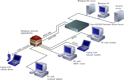
To place an order, contact Cisco Customer Service at 408 526-4000 or 800 553-6387.
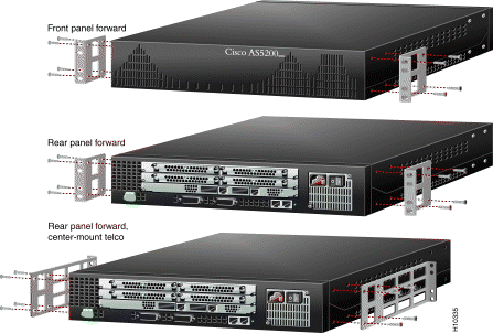
You can install the chassis in a rack or on a desktop. For a desktop installation, proceed to the next section, "Prepare the Chassis for Desktop Use."
Step 1 Attach the brackets using one of the three methods shown above.
Step 2 Install the chassis in a rack.
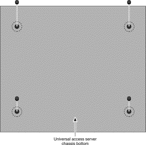
Attach the rubber feet before installing the chassis on a desktop.
Step 1 Locate the rubber feet on the black adhesive strip that shipped with the chassis.
Step 2 Place the access server upside-down on a flat, smooth surface.
Step 3 Peel off the rubber feet from the black adhesive strip and place them adhesive-side down on the dotted circles at each corner of the chassis bottom.
Step 4 Place the access server right-side up on a flat, smooth, secure surface.
 | Caution Do not place anything that weighs more than 10 lb (4.5 kg) on top of the access server. Excessive weight placed on top of the chassis could damage it. |
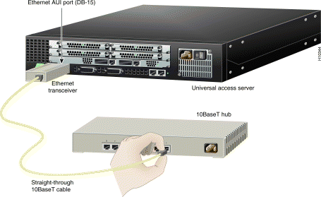
You can connect the access server to a 10BaseT or thick Ethernet network. For a thick Ethernet connection, proceed to the next section, "Connect the Ethernet Port for Thick Ethernet LAN Access."
You will need an Ethernet transceiver and cable to connect the access server to a 10BaseT hub.
Step 1 Connect an Ethernet transceiver to the port labeled AUI on the rear panel of the access server.
Step 2 Connect an Ethernet cable to the Ethernet transceiver.
Step 3 Connect the other end of the Ethernet cable to a 10BaseT hub.
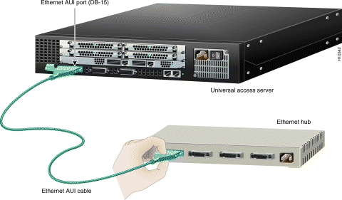
You will need an Ethernet AUI cable to connect the access server to a hub.
Step 1 Connect your Ethernet AUI cable to the port labeled AUI on the rear panel of the access server.
Step 2 Connect the other end of the Ethernet cable to an Ethernet hub.
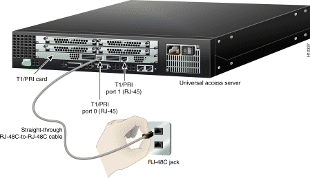
You can connect the access server to a dual T1 or E1/PRI card for WAN access. If you have a dual E1/PRI card, go to the next section, "Connect the Dual E1/PRI Card for WAN Access."
You will need two straight-through RJ-48C-to-RJ-48C cables to connect the dual T1/PRI card to a WAN.
Step 1 Connect one end of the straight-through RJ-48C-to-RJ-48C cable to the port labeled Port 0 on the rear panel of the access server.
Step 2 Connect the other end of the cable to an RJ-48C jack.
Step 3 Repeats steps 1 and 2 to connect a second cable to the port labeled Port 1.
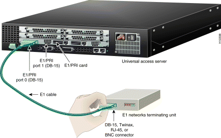
You will need two E1 cables to connect the dual E1/PRI card to a WAN.
Step 1 Connect one end of the E1 cable to the port labeled Port 0 on the rear panel of the access server.
Step 2 Connect the other end of the cable to an
E1 networks terminating unit.
Step 3 Repeats steps 1 and 2 to connect a second cable to the port labeled Port 1.
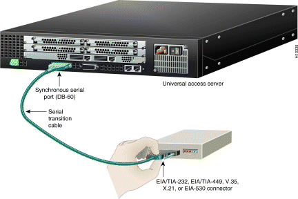
You will need two CSU/DSUs or modems and two serial transition cables to connect the synchronous serial ports to a WAN.
Step 1 Connect one end of a serial transition cable to the port labeled Serial.
Step 2 Connect the other end of the cable to a CSU/DSU or other DCE (such as a modem).
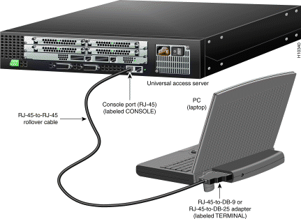
You will need an RJ-45-to-RJ-45 rollover cable and a terminal adapter (RJ-45-to-DB-9 or RJ-45-to-DB-25) to connect a console. These cables and adapters are included. Take these steps:
Step 1 Connect one of the adapters, labeled TERMINAL, to the communications port (usually labeled COM) on your
PC or terminal. (This communications port is also known as a console.)
Step 2 Connect one end of the RJ-45-to-RJ-45 rollover cable to the adapter.
Step 3 Connect the other end of the RJ-45-to-RJ-45 rollover cable to the port labeled CONSOLE on the rear panel of the access server.
Step 4 Configure your PC terminal emulation software or terminal for 9600 baud, 8 data bits, no parity, and 1 stop bit.
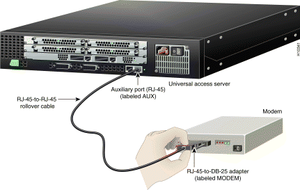
To configure the access server from a remote location, you will need an RJ-45-to-RJ-45 rollover cable and a modem adapter (RJ-45-to-DB-25) to connect a modem.
If you will not be using a modem to configure the access server remotely, skip this procedure and go to the next page.
Step 1 Connect the adapter labeled MODEM to your modem.
Step 2 Connect the RJ-45-to-RJ-45 rollover cable to the adapter.
Step 3 Connect the other end of the RJ-45-to-RJ-45 rollover cable to the port labeled AUX on the rear panel of the access server.
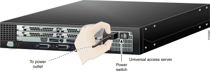
Step 1 Connect one end of the power cord to the power connector on the rear panel of the access server.
Step 2 Connect the other end of the power cord to the power outlet.
Step 3 Power ON the access server. Messages will begin to appear on your console screen.
 | Caution kIt may take several minutes for the startup messages to stop. Do not press any keys until you see the following message:Would you like to enter the initial configuration dialog? [yes]: While you are waiting for this message to appear, proceed to Section 3 . |
Use any of the following options for configuring your universal access server:
The option you select depends on how you want to configure your universal access server. Use the information on this page to help you decide which option to select.
Cisco Fast Step is a setup utility with a graphical user interface. It provides easy, step-by-step instructions for setting up some of the most commonly used options available on the Cisco AS5200 universal access server. Use Cisco Fast Step to configure your access server with the following options:
For all other configurations, use the Cisco IOS Release setup script or the command line interface. Refer to the Cisco AS5200 Universal Access Server Software Configuration Guide for detailed instructions on using the command line interface to configure your Cisco AS5200 universal access server.
 | TimeSaver Use Appendix A to help you gather the appropriate information before you begin to configure the access server using the setup script. |
1. Insert the Cisco Fast Step CD-ROM (attached to the inside back cover of this guide) into the CD-ROM drive of the local PC you connected in Section 2 .
2. The Fast Step install program starts Setup.exe automatically. If it does not, use the following steps to start the Fast Step program:
(a) Double-click the My Computer icon on your computer desktop.
(b) Double-click the CD icon.
(c) Double-click the Setup.exe icon.
Once installed, the Cisco Fast Step setup program starts automatically. Follow the onscreen instructions to guide you through configuring and testing the universal access server.
Use this appendix to note the information you may need for configurating your universal access server. You can get this information from your network administrator.
| Item | Ask Your Network Administrator | Enter the Information in This Column |
| 1 |
|
|
| 2 |
|
|
| 3 |
|
|
| 4 |
|
|
| 5 |
|
|
|
| |
|
| |
|
| |
|
| |
|
| |
|
| |
|
| |
|
| |
|
| |
|
| |
|
| |
|
| |
|
| |
|
| |
|
| |
|
| |
|
| |
|
| |
|
|
| Item | Ask Your Network Administrator | Enter the Information in This Column |
| 6 |
|
|
| 7 |
|
|
| 8 |
|
|
| 9 |
|
|
| 10 |
|
|
| 11 |
|
|
| 12 |
|
|
| 13 |
|
|
| 14 |
|
|
| Item | Ask Your Network Administrator | Enter the Information in This Column |
| 15 |
|
|
| 16 |
|
|
| 17 |
|
|
![]()
![]()
![]()
![]()
![]()
![]()
![]()
![]()
Posted: Mon Sep 16 10:54:11 PDT 2002
All contents are Copyright © 1992--2002 Cisco Systems, Inc. All rights reserved.
Important Notices and Privacy Statement.