|
|

These release notes describe how to connect 48 VDC power to the Cisco 6510 Service Selection Gateway. This information replaces Step 2, page 1-3, of the Cisco 6510 Service Selection Gateway Hardware Installation Guide.
This document contains the following sections.
The following tools and equipment are needed for this procedure:
Step 1 Read the Regulatory Compliance and Safety Information for the Cisco 6510 Service Selection Gateway to learn about important safety notices and compliance parameters. This document is supplied with your Cisco 6510 Service Selection Gateway.
| Warning Before working on equipment that is connected to power lines, remove jewelry (including rings, necklaces, and watches). Metal objects will heat up when connected to power and ground and can cause serious burns or weld the metal object to the terminals. |
Step 2 Assure that the Cisco 6510 is physically installed in accordance to Step 1, page 1-3, of the Cisco 6510 Service Selection Gateway hardware Installation Guide.
| Warning Read the installation instructions before you connect the system to its power source. |
Step 3 Assure the Cisco 6510 is turned OFF.
| Warning Before working on a chassis or working near power supplies, unplug the power cord on AC units; disconnect the power at the circuit breaker on DC units. |
Step 4 Assure the 48 VDC power can supply 15A of current.
| Warning A readily accessible two-poled disconnect device must be incorporated in the fixed wiring. |
Step 5 Assure the power is supplied through a 15A circuit breaker and that the circuit breaker is turned OFF.
| Warning Before performing any of the following procedures, ensure that power is removed from the DC circuit. To ensure that all power is OFF, locate the circuit breaker on the panel board that services the DC circuit, switch the circuit breaker to the OFF position, and tape the switch handle of the circuit breaker in the OFF position. |
| Warning This product relies on the building's installation for short-circuit (overcurrent) protection. Ensure that a fuse or circuit breaker no larger than 120 VAC, 15A U.S. (240 VAC, 10A international) is used on the phase conductors (all current-carrying conductors). |
Step 6 Assure an earth ground is available.
Step 7 Assure that the power cable has three 14 AWG wires for making positive, negative, and ground connections.
Step 8 Determine a path from the circuit breaker to the 48 VDC connector on the Cisco 6510, and then measure and record the path distance.
Step 9 Determine a path from to the earth ground supplied by your facility to the back panel on the Cisco 6510, and then measure and record the path distance.
Step 1 Cut the ground cable to the length required.
Step 2 Using a connection approved by the National Electric Code, attach one end of the ground cable to your facility's earth ground.
Step 3 Using the path determined for your ground cable, thread the other end of the cable to the back panel of the Cisco 6510.
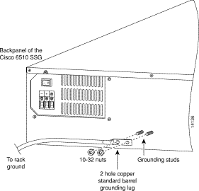
Step 4 Attach the two hole copper barrel lug to the end of the ground cable, then use two 10-32 nuts to connect the lug to the back of the Cisco 6510 as shown in Figure 1.

Step 5 Cut the power cable to the length required.
Step 6 From one end of the power cable, appropriately strip 3/8 of an inch of insulation from the wires.
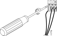
Step 7 Connect the power cable to the Cisco 6510 by fastening the stripped end to the 48 VDC connector as shown in Figure 2.
| Warning Note the wire colors used for making the positive, negative, and ground connections. Use the same color assignment for the connection at the circuit breaker. |
| Warning The illustration shows the DC power supply terminal block. Wire the DC power supply using the appropriate lugs at the wiring end, as illustrated. The proper wiring sequence is ground to ground, positive to positive and negative to negative. Note that the ground wire should always be connected first and disconnected last. |

Step 8 Using the path determined for your power cable, thread the other end of the cable to the 15A circuit breaker.
Step 9 Appropriately dress the end of the power cable so that it can be connected to the 15A circuit breaker.
Step 10 Assure the circuit breaker is in the OFF position.
Step 11 Connect the dressed end of the power cable to the circuit breaker.
| Caution Assure that the wire colors used for making the positive, negative, and ground connections are the same color assignments used on the Cisco 6510's 48 VDC connector. |
Step 12 Switch the circuit breaker to the ON position.
| Warning After wiring the DC power supply, remove the tape from the circuit breaker switch handle and reinstate power by moving the handle of the circuit breaker to the ON position. |
Step 13 Continue the installation process with Step 3, page 1-4, of the Cisco 6510 Service Selection Gateway Hardware Installation Guide.
Cisco documentation and additional literature are available in a CD-ROM package, which ships with your product. The Documentation CD-ROM, a member of the Cisco Connection Family, is updated monthly. Therefore, it might be more current than printed documentation. To order additional copies of the Documentation CD-ROM, contact your local sales representative or call customer service. The CD-ROM package is available as a single package or as an annual subscription. You can also access Cisco documentation on the World Wide Web at http://www.cisco.com, http://www-china.cisco.com, or http://www-europe.cisco.com.
If you are reading Cisco product documentation on the World Wide Web, you can submit comments electronically. Click Feedback in the toolbar and select Documentation. After you complete the form, click Submit to send it to Cisco. We appreciate your comments.
Cisco Connection Online (CCO) is Cisco Systems' primary, real-time support channel. Maintenance customers and partners can self-register on CCO to obtain additional information and services.
Available 24 hours a day, 7 days a week, CCO provides a wealth of standard and value-added services to Cisco's customers and business partners. CCO services include product information, product documentation, software updates, release notes, technical tips, the Bug Navigator, configuration notes, brochures, descriptions of service offerings, and download access to public and authorized files.
CCO serves a wide variety of users through two interfaces that are updated and enhanced simultaneously: a character-based version and a multimedia version that resides on the World Wide Web (WWW). The character-based CCO supports Zmodem, Kermit, Xmodem, FTP, and Internet e-mail, and it is excellent for quick access to information over lower bandwidths. The WWW version of CCO provides richly formatted documents with photographs, figures, graphics, and video, as well as hyperlinks to related information.
You can access CCO in the following ways:
For a copy of CCO's Frequently Asked Questions (FAQ), contact cco-help@cisco.com. For additional information, contact cco-team@cisco.com.

|
|