|
|

Table Of Contents
Cisco 3620 and Cisco 3640 Modular Access Routers
Cisco 90-Day Limited Hardware Warranty Terms
Documents, Equipment, and Tools
Items Included with Cisco 3620 and Cisco 3640 Routers
WAN, LAN, and Voice Connections
Initial Configuration Using Cisco Router and Security Device Manager
Initial Configuration Using the Setup Command Facility
Initial Configuration Using the CLI (Manual Configuration)
Obtaining Technical Assistance
Cisco Technical Support Website
Definitions of Service Request Severity
Obtaining Additional Publications and Information
Quick Start Guide
Cisco 3620 and Cisco 3640 Modular Access Routers
INCLUDING LICENSE AND WARRANTYInstallation, License and Warranty
1 Cisco 90-Day Limited Hardware Warranty Terms
There are special terms applicable to your hardware warranty and various services that you can use during the warranty period. Your formal Warranty Statement, including the warranties and license agreements applicable to Cisco software, is available on Cisco.com. Follow these steps to access and download the Cisco Information Packet and your warranty and license agreements from Cisco.com.
1.
Launch your browser, and go to this URL:
http://www.cisco.com/univercd/cc/td/doc/es_inpck/cetrans.htm
The Warranties and License Agreements page appears.
2.
a.
b.
c.
d.
Note
3.
a.
b.
c.
d.
You can also contact the Cisco service and support website for assistance:
http://www.cisco.com/public/Support_root.shtml.
Duration of Hardware Warranty
Ninety (90) days.
Replacement, Repair, or Refund Policy for Hardware
Cisco or its service center will use commercially reasonable efforts to ship a replacement part within ten (10) working days after receipt of a Return Materials Authorization (RMA) request. Actual delivery times can vary, depending on the customer location.
Cisco reserves the right to refund the purchase price as its exclusive warranty remedy.
To Receive a Return Materials Authorization (RMA) Number
Contact the company from whom you purchased the product. If you purchased the product directly from Cisco, contact your Cisco Sales and Service Representative.
Complete the information below, and keep it for reference:
Company product purchased from
Company telephone number
Product model number
Product serial number
Maintenance contract number
2 Documents, Equipment, and Tools
User Documentation
All the documents referenced in this quick start guide are available online and on the Cisco documentation CD-ROM. To be sure of obtaining the latest information, you should access the online documentation.
To view or print a document in its original page format, access the online document, and click on the PDF icon.
For information about accessing user documentation, see the "Where to Go Next" section.
Items Included with Cisco 3620 and Cisco 3640 Routers
•
•
•
•
•
•
Items Not Included
Individual items in this list may be required for your particular application:
•
•
•
•
•
•
3 Install Chassis
Safety Information
For safety information you need to know before working on your Cisco router, refer to the Cisco 2600 Series, Cisco 3600 Series, and Cisco 3700 Series Regulatory Compliance and Safety Information document that accompanied this device.
Note
Warning Definition
Warning
Warning
Warning
Warning
Warning
Warning
Warning
Warning
Warning
Installing the Chassis
You can set the chassis on a desktop or install it in a rack. A Cisco 3620 chassis can also be mounted on a wall or other flat surface. See the applicable instructions following.
Caution
Rack-Mounting the Chassis
The standard accessory kit contains brackets for mounting the chassis in a 19-inch rack. You can order an optional accessory kit with brackets and instructions for mounting the chassis in a 23- or 24-inch rack.
You can mount the chassis in the following ways:
•
•
•
Note
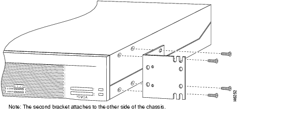
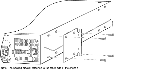
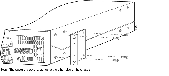
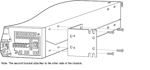
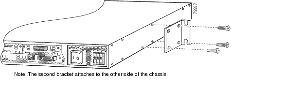
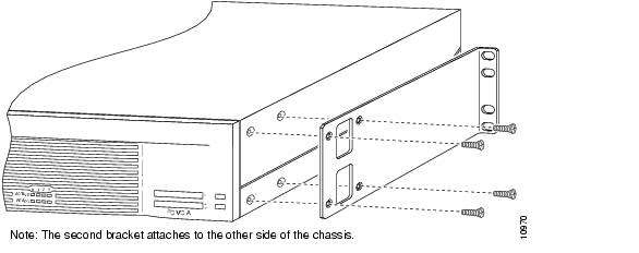
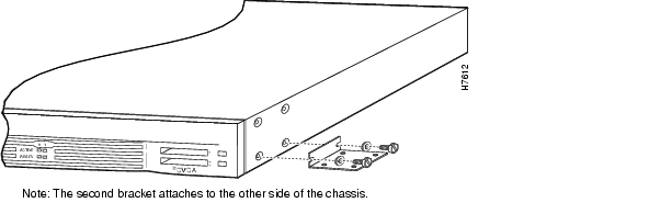
Attaching Brackets
Attach the mounting brackets to the chassis as shown in the applicable figure, Figure 1 through Figure 8, using the Phillips-head screws provided. Attach the second bracket to the opposite side of the chassis.
Note
Figure 1 Cisco 3620 or Cisco 3640 Bracket Attachment—Front Panel Forward (19-Inch Rack with a 17.5-Inch Opening)
Figure 2 Cisco 3620 or Cisco 3640 Bracket Attachment—Front Panel Forward (19-Inch Rack with a 17.75-Inch Opening)
Figure 3 Cisco 3620 or Cisco 3640 Bracket Attachment—Front Panel Forward (23- or 24-Inch Rack)
Figure 4 Cisco 3620 or Cisco 3640 Bracket Attachment—Rear Panel Forward (19-Inch Rack with a 17.5-Inch Opening)
Figure 5 Cisco 3620 or Cisco 3640 Bracket Attachment—Rear Panel Forward (19-Inch Rack with a 17.75-Inch Opening)
Figure 6 Cisco 3620 or Cisco 3640 Bracket Attachment—Rear Panel Forward (23- or 24-Inch Rack)
Figure 7 Cisco 3620 Center-Mount Bracket Attachment
Figure 8 Cisco 3640 Center-Mount Bracket Attachment (Requires Optional NEBS/ETSI Kit)
Installing Chassis in Rack
Install the chassis in the rack, using the screws provided with the rack. Rack-mounting screws are not provided with the router. Use two screws for each side.
Wall-Mounting the Cisco 3620 Chassis
Attaching Rubber Feet
If you are mounting a Cisco 3620 on a wall, you must install the rubber feet that are supplied in the accessory kit. They provide a space for air circulation. Peel the rubber feet from the adhesive strip, and attach one foot at each corner to the bottom of the chassis. Cisco 3640 routers are not suitable for wall-mounting.
Attaching Brackets
Attach the brackets to the chassis as shown in Figure 9, using the slotted hex-head screws and plastic spacers (supplied in the accessory kit). Orient each spacer so that the shoulder fits into the slot in the bracket. Attach the second bracket to the opposite side of the chassis.
Figure 9 Attaching the Brackets for Wall-Mounting a Cisco 3620 Router
Attaching to Wall
Attach the chassis to the wall:
•
•
Installing on a Desktop
If you are mounting a Cisco 3620 on a desktop, you must install the rubber feet that are supplied in the accessory kit. They provide a space for air circulation. Peel the rubber feet from the adhesive strip, and attach one foot at each corner to the bottom of the chassis.
Caution
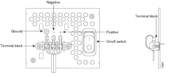
Grounding the Chassis
You must connect the chassis to a reliable earth ground; the ground wire must be installed in accordance with local electrical safety standards.
•
•
•
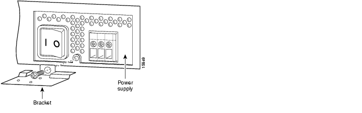
To connect the chassis to a reliable earth ground, perform the following steps:
Step 1
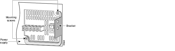
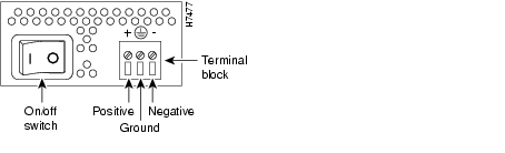
For Cisco 3620 routers, use the power-supply retaining screw located at the bottom of the power supply.
For Cisco 3640 routers, use the two power-supply retaining screws: one at the lower left and one at the upper right.
A DC power supply is shown. The ground-lug bracket attachment is similar for an AC power supply and for a Cisco redundant power supply (RPS).
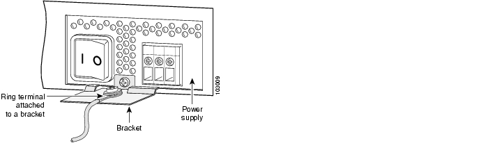
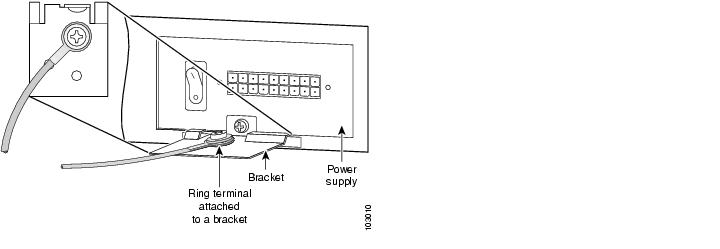
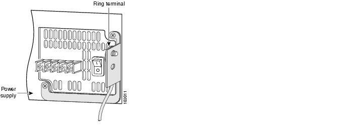
Figure 10 Required Ground-Lug Bracket Attachment on a Cisco 3620 Router (DC Power Supply Shown)
Figure 11 Required Ground-Lug Bracket Attachment on a Cisco 3640 Router (DC Power Supply Shown)
Step 2
•
•
Step 3
Step 4
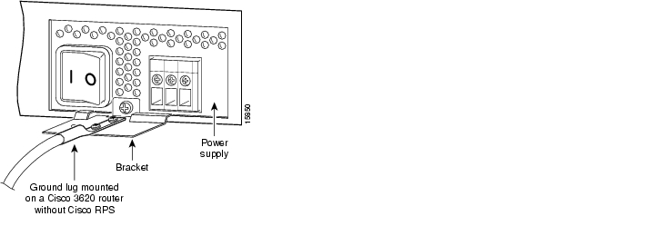
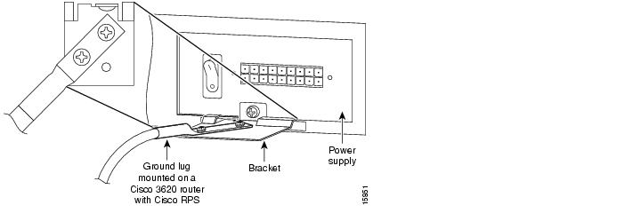
Where a DC power supply is shown, the attachment would be similar for an AC power supply.
Diagonal attachment of the ground lug to the bracket provides clearance for the RPS power cable.
Step 5
Figure 12 NEBS-Compliant Ground Lug Attachment on a Cisco 3620 Router with Internal AC or DC Power Supply
Figure 13 NEBS-Compliant Ground Lug Attachment on a Cisco 3620 Router with Redundant Power Supply (Cisco RPS)
Figure 14 NEBS-Compliant Ground Lug Attachment on a Cisco 3640 Router
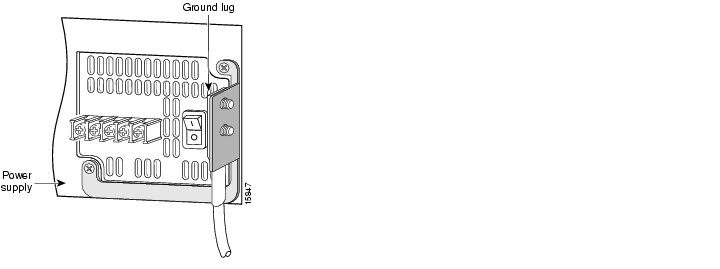
Figure 15 Ground Lug Attachment Using Ring Terminal on a Cisco 3620 Router with Internal AC or DC Power Supply
Figure 16 Ground Lug Attachment Using Ring Terminal on a Cisco 3620 Router with Redundant Power Supply (Cisco RPS)
Figure 17 Ground Lug Attachment Using Ring Terminal on a Cisco 3640 Router
4 Connect Cables
Warning
System Management Connections
The connections described in Table 1 provide system management access.
Power Connections
Warning
Note
Connecting Routers to AC Power
If your router uses AC power, connect it to a 15 A, 120 VAC (10A, 240 VAC) circuit with overcurrent protection.
Note
Warning
Warning
15A, 120VAC (10A, 240VAC). Statement 1005
Connecting Routers to DC Power
If your router has a DC-input power supply, follow the directions in this section for proper wiring.
Warning
15A, 60VDC. Statement 1005
Warning
DC Wiring Requirements
Cisco 3620 and Cisco 3640 routers with a DC-input power supply require copper wire for the power connections.
For Cisco 3640 routers, DC power connections require crimp-type ring terminals or spade terminals with upturned lugs.
Table 2 DC Wiring Requirements for Cisco 3620 and Cisco 3640 Routers
Nominal 48 VDC
-48 to -60 VDC1 , 4A
AWG 14 (2.0 mm2)
AWG 14 (2.0 mm2)
15A, maximum
1 The input voltage tolerance limits for nominal 48 V power supplies are 38 and 72 VDC.
Wiring Procedure for DC Input
To connect the router to a DC power source, perform this procedure.
Step 1
Warning
Tip
Step 2
For Cisco 3640 routers, crimp appropriate ring terminals or spade terminals to the DC power input wires. Strip the wires to the appropriate length for the terminals used. The following warning applies to Cisco 3640 routers:
Warning
Step 3
Warning
Warning
Caution
Caution
Figure 18 DC Power Connections for Cisco 3620 Routers (Typical)
Figure 19 DC Power Connections for Cisco 3640 Routers (Typical)
Step 4
Step 5
Connecting Routers to the Cisco Redundant Power System
If your router uses the Cisco Redundant Power System (RPS), refer to the Cisco RPS Hardware Installation Guide for instructions about the power connections.To locate these documents, see the "Where to Go Next" section.
WAN, LAN, and Voice Connections
The connections described here are described in detail in the following documents:
•
•
•
•
To locate these documents, see the "Where to Go Next" section.
Table 3 summarizes some typical WAN, LAN, and voice connections for Cisco 3600 series routers.
Table 3 WAN, LAN, and Voice Connections
Ethernet
RJ-45, yellow
Ethernet hub
Straight-through Ethernet
T1/E1 WAN
RJ-48C/CA81A, blue
Network demarcation (telco demarc or equivalent)
RJ-48 T1
Cisco serial
60-pin D-sub
CSU/DSU and serial network or equipment
Cisco serial transition cable that matches the signaling protocol (EIA/TIA-232, EIA/TIA-449, V.35, X.21, or EIA/TIA-530) and the serial port operating mode (DTE or DCE).1
Cisco Smart serial
Cisco Smart compact connector, blue
CSU/DSU and serial network or equipment (For WIC-2T and WIC-2A/S only)
DSL
RJ-11C/CA111A, lavender
Network demarcation device for service provider's DSL interface
RJ-11
T1 Digital voice
RJ-48C/CA81A, tan
Digital PBX
RJ-48 T1 cable
Analog voice FXS
RJ-11, gray
Telephone, fax
RJ-11
Analog voice FXO
RJ-11, pink
Central office, analog PBX
RJ-11
Analog voice E&M
RJ-11, brown
Analog PBX
RJ-11
BRI S/T WAN
(external NT1)RJ-48C/CA81A, orange
NT1 device or private integrated network exchange (PINX)
RJ-48
BRI U WAN
(built-in NT1)RJ-49C/CA-A11, red
ISDN network
RJ-49
BRI S/T LL
(external NT1)RJ-48C/CA81A, orange
NT1 device
RJ-48
CT1/PRI
T1
External T1 CSU
DB-15 T1 serial cable
CT1/PRI-CSU
T1
RJ-48C/CA81A interface
RJ-48 straight-through
CTE/PRI
E1
E1 network
DB-15 to BNC, DB-15 to DB-15,
DB-15 to twinax, or DB-15 to RJ-45Token Ring
UTP, purple
STP, purple
Token Ring device
RJ-45 Token Ring cable
56/64-kbps DSU/CSU
8-pin modular, blue
RJ-48S interface
RJ-48 straight-through
1 See the Cisco Modular Access Router Cable Specifications document for information about selecting these cables.
5 Power Up the Router
Checklist for Power-Up
You are ready to power up the Cisco router if the following steps are completed:
•
•
•
•
•
Front Panel Indicators
The following indicator LEDs provide power, activity, and status information:
•
•
–
–
–
•
Power-Up Procedure
Perform this procedure to power up your Cisco router and verify that it goes through its initialization and self-test. When the procedure is finished, the Cisco router is ready to configure.
Note
Step 1
Step 2
The green LED next to the auxiliary port comes on and the fan operates. If this does not happen, see the power-up procedure in the Cisco 3600 Series Routers Hardware Installation Guide.
Messages begin to appear in your terminal emulation program window.
Caution
You may see different startup messages:
•
yourname con0 is now availablePress RETURN to get started.See the "Initial Configuration Using Cisco Router and Security Device Manager" section to learn how to configure your router using SDM or to learn how to obtain SDM and install it on your router.
•
--- System Configuration Dialog ---At any point you may enter a question mark '?' for help.Use ctrl-c to abort configuration dialog at any prompt.Default settings are in square brackets '[]'.Would you like to enter the initial configuration dialog? [yes/no]:To learn how to use the Setup Command Facility to configure the router, see the "Initial Configuration Using the Setup Command Facility" section. To learn how to use the CLI to configure the router, see the "Initial Configuration Using the CLI (Manual Configuration)" section.
Note
rommon 1>prompt appears, your system has booted in ROM monitor mode. For information on the ROM monitor, see the router rebooting and ROM monitor information in the Cisco IOS Configuration Fundamentals Configuration Guide for your Cisco IOS software release.
You can access this document at the locations described in the "Where to Go Next" section.
6 Perform Initial Configuration
You can configure your router by using one of the following methods:
•
•
•
Note
Initial Configuration Using Cisco Router and Security Device Manager
This section explains how to use Cisco Router and Security Device Manager (SDM) to configure your router. If SDM has been installed on your router, the following messages appear at the end of the startup sequence:
yournname con0 is now availablePress RETURN to get started.SDM is a web-based configuration tool that allows you to configure LAN and WAN interfaces, routing, Network Address Translation (NAT), firewalls, Virtual Private Networks (VPNs), and other features on your router. SDM runs on a PC connected to the router through an Ethernet or Fast Ethernet interface, and it requires a web browser, either Internet Explorer version 5.5 or later or Netscape version 4.79. SDM is compatible with Microsoft Windows 2000, Windows NT 4.0 (with Service Pack 4), Windows 98, Windows ME, and Microsoft Windows XP.
To configure your router by using SDM, first assign an IP address to the Ethernet port of the PC as directed in the "Assign a Static IP Address to the PC" section, and then start SDM as described in the "Start SDM" section.
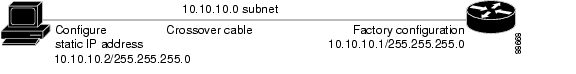
Assign a Static IP Address to the PC
Assign a static IP address in the 10.10.10.0 subnet to the Ethernet port of the PC. (See Figure 20.) The recommended IP address for this interface is 10.10.10.2. The Fast Ethernet 0/0 interface of the router is preconfigured with the IP address 10.10.10.1.
Figure 20 Initial IP Addresses in the 10.10.10.0 Subnet for SDM
If Your Router Has No Ethernet Adapter in Slot 0
Cisco 3620 and Cisco 3640 routers have no built-in Ethernet ports. However, many of these routers ship with a Fast Ethernet network module in chassis slot 0. The SDM default configuration file assumes this to be the case. If your router has no Ethernet module in chassis slot 0, you need to do one of the following:
•
•
Note
Step 1
Step 2
Step 3
If Ethernet port 0/0 is not configured with IP address 10.10.10.1, SDM is not installed on your router, and you must use the setup command facility or the command-line interface to configure the router.
Step 4
yourname# config tStep 5
yourname (config)# interface FastEthernet 0/0yourname (config-if)#Step 6
yourname (config-if)# no ip address 10.10.10.1 255.255.255.0Step 7
yourname (config-if)# exitStep 8
yourname (config)# interface FastEthernet 1/0yourname (config-if)#Step 9
yourname (config-if)# ip address 10.10.10.1 255.255.255.0Step 10
Step 11
yourname (config-if)# exitStep 12
Step 13
yourname (config)# exitStep 14
Start SDM
To start SDM and begin the router configuration, perform the following procedure:
Step 1
Step 2
https://10.10.10.1/flash/sdm.shtml
Note
Step 3
Step 4
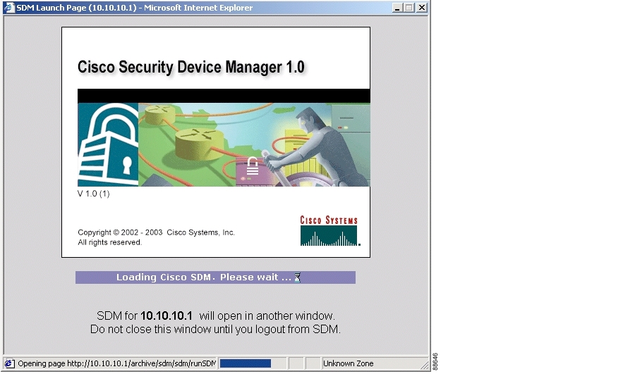
The SDM Launch page appears after a short time. (See Figure 21.) Leave this window open and wait for the next window.
Figure 21 SDM Launch Page
Tip
a.
b.
c.
d.
Step 5
Step 6
Tip
Step 7
Step 8
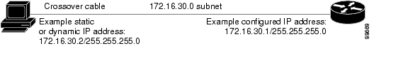
Figure 22 IP Addresses in the Renumbered Subnet for SDM
Step 9
https://new-IP-address/flash/sdm.shtml
In the Figure 22 example, you would enter:
https://172.16.30.1/flash/sdm.shtml.
Step 10
Step 11
For more information about SDM, refer to the Cisco Router and Security Device Manager Troubleshooting Guide at the following URL:
http://www.cisco.com/go/sdm
See the "Obtaining Documentation" section for information about accessing this document.
Initial Configuration Using the Setup Command Facility
This section shows how to use the setup command facility to configure a host name for the router, set passwords, and configure an interface for communication with the management network. If you see the following messages at the end of the startup sequence, the setup command facility has been invoked automatically:
--- System Configuration Dialog ---At any point you may enter a question mark '?' for help.Use ctrl-c to abort configuration dialog at any prompt.Default settings are in square brackets '[]'.Would you like to enter the initial configuration dialog? [yes/no]:The setup command facility prompts you for basic information about your router and network, and it creates an initial configuration file.The prompts vary, depending on your router model, the installed interface modules, and the software image. The following example and the user entries (in bold) are shown as examples only.
For a description of the interface numbering, see the "Interface Numbering" section.
Note
Step 1
Would you like to enter the initial configuration dialog? [yes/no]: yesStep 2
At any point you may enter a question mark '?' for help.Use ctrl-c to abort configuration dialog at any prompt.Default settings are in square brackets '[]'.Basic management setup configures only enough connectivityfor management of the system, extended setup will ask youto configure each interface on the systemWould you like to enter basic management setup? [yes/no]: yesStep 3
Configuring global parameters:Enter host name [Router]: 3600The enable secret is a password used to protect access to privileged EXEC and configuration modes. This
password, after entered, becomes encrypted in the configuration.Step 4
Enter enable secret: xxxxThe enable password is used when you do not specify an enable secret password, with some older software
versions, and some boot images.Step 5
Enter enable password: xxxxThe virtual terminal password is used to protect access to the router over a network interface.Step 6
Enter virtual terminal password: xxxxStep 7
Configure SNMP Network Management? [yes]: yesCommunity string [public]:Step 8
Note
Current interface summaryAny interface listed with OK? value "NO" does not have a valid configurationInterface IP-Address OK? Method Status ProtocolFastEthernet0/0 unassigned NO unset up upFastEthernet0/1 unassigned NO unset up downStep 9
Enter interface name used to connect to themanagement network from the above interface summary: fastethernet0/0Step 10
Configuring interface FastEthernet0/0:Use the 100 Base-TX (RJ-45) connector? [yes]:Operate in full-duplex mode? [no]: yesConfigure IP on this interface? [yes]:IP address for this interface: 10.1.1.1Subnet mask for this interface [255.0.0.0] : 255.255.0.0Class A network is 10.0.0.0, 16 subnet bits; mask is /16Step 11
The following configuration command script was created:hostname 3600enable secret 5 $1$Ksjf$za4T2lb3ARS5d1PHVzW5A0enable password xxxxline vty 0 4password xxxxsnmp-server community public!no ip routing!interface FastEthernet0/0no shutdownmedia-type 100BaseXfull-duplexip address 10.1.1.1 255.255.0.0!interface FastEthernet0/1shutdownno ip address!end[0] Go to the IOS command prompt without saving this config.[1] Return back to the setup without saving this config.[2] Save this configuration to nvram and exit.Enter your selection [2]: 2% You can enter the setup, by typing setup at IOS command promptPress RETURN to get started! RETURNStep 12
3600>When you have completed the initial configuration tasks, your Cisco router is ready to configure for specific functions. See the "Where to Go Next" section for information about locating documentation for advanced configuration procedures.
Initial Configuration Using the CLI (Manual Configuration)
This section shows how to bring up a command-line interface (CLI) prompt for configuration using the CLI, and it directs you to documentation for the CLI configuration.You can use the CLI if you see the following messages at the end of the startup sequence:
--- System Configuration Dialog ---At any point you may enter a question mark '?' for help.Use ctrl-c to abort configuration dialog at any prompt.Default settings are in square brackets '[]'.Would you like to enter the initial configuration dialog? [yes/no]:If these messages do not appear, SDM and a default configuration file have been installed on the router at the factory. To use SDM to configure the router, see the "Initial Configuration Using Cisco Router and Security Device Manager" section.
Step 1
Would you like to enter the initial configuration dialog? [yes/no]: noStep 2
Would you like to terminate autoinstall? [yes] ReturnSeveral messages are displayed, ending with a line similar to the following:...Copyright (c) 1986-2000 by cisco Systems, Inc.Compiled <date> <time> by <person>Step 3
...flashfs[4]: Initialization complete.Router>Step 4
Router> enableRouter#
Note
For configuration using the CLI, refer to the applicable configuration procedures in the Software Configuration Guide: Cisco 2600 Series, Cisco 3600 Series, and Cisco 3700 Series Routers. See the "Where to Go Next" section for information about accessing this document.
7 Interface Numbering
Each individual network interface on a Cisco 3620 or Cisco 3640 router is identified by a slot number and a unit number.
Slot Numbering
The Cisco 3620 or Cisco 3640 router chassis contains two or four slots in which you can install modules. You can install any module into any available slot in the chassis. For Cisco 3620 and Cisco 3640 routers, the slots are numbered as follows:
•
•
•
•
Unit Numbering
Cisco 3600 series routers have unit numbers that identify the interfaces on the modules and WAN interface cards installed in the router. Unit numbers begin at 0 for each interface type, and continue from right to left and (if necessary) from bottom to top. Modules and WAN interface cards are identified by interface type, slot number, followed by a forward slash (/), and then the unit number; for example, Ethernet 0/0.
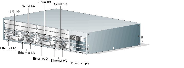
Figure 23 shows a router with a 2E 2-slot module in slots 0 and 1. Two serial WAN interface cards are installed in the module in slot 0. One serial and one ISDN BRI WAN interface card are installed in the module in slot 1.
Figure 23 Cisco 3600 Series Unit Numbers
Voice Interface Numbering
Voice interfaces are numbered as follows:
interface-type chassis-slot/voice-module-slot/voice-interface
For example, Slot 1, voice network module slot 0, is referred to as voice 1/0/0 (closest to chassis slot 0).
8 Where to Go Next
For additional detailed configuration procedures, refer to the appropriate Cisco 3600 series documentation or Cisco IOS software documentation, available online and on the Documentation CD-ROM:
Tip
To access Cisco 3600 series platform documentation on Cisco Connection Online (CCO):
On the Cisco.com home page at http://www.cisco.com, locate the Technical Documentation tab, and click on "Locate Technical Documentation on Cisco Connection Online." Under the Product Documentation heading, navigate to Modular Access Routers and to the documentation for your router.
To access Cisco IOS software documentation on Cisco Connection Online (CCO):
On the Cisco.com home page at http://www.cisco.com, locate the Technical Documentation tab, and click on "Locate Technical Documentation on Cisco Connection Online." Under the Product Documentation heading, navigate to the Cisco IOS software documentation for the Cisco IOS software release that is installed on your router.
To access documentation on Cisco.com:
For Cisco 3600 series platform documentation, start on Cisco.com at http://www.cisco.com, and select Products & Services > Routers > Cisco 3600 Series Multiservice Platforms > Technical Documentation > Document type > Document.
For Cisco IOS software documentation, start on Cisco.com at http://www.cisco.com, and select Products & Services > IOS Software > Cisco IOS Software Releases > Your Cisco IOS software release.
To get updated information about platform support for features, select Feature Navigator II, if you have an account on Cisco.com. You can also access Feature Navigator II at http://www.cisco.com/go/fn.
9 Obtaining Documentation
Cisco documentation and additional literature are available on Cisco.com. Cisco also provides several ways to obtain technical assistance and other technical resources. These sections explain how to obtain technical information from Cisco Systems.
Cisco.com
You can access the most current Cisco documentation at this URL:
http://www.cisco.com/univercd/home/home.htm
You can access the Cisco website at this URL:
You can access international Cisco websites at this URL:
http://www.cisco.com/public/countries_languages.shtml
Ordering Documentation
You can find instructions for ordering documentation at this URL:
http://www.cisco.com/univercd/cc/td/doc/es_inpck/pdi.htm
You can order Cisco documentation in these ways:
•
http://www.cisco.com/en/US/partner/ordering/index.shtml
•
10 Documentation Feedback
You can send comments about technical documentation to bug-doc@cisco.com.
You can submit comments by using the response card (if present) behind the front cover of your document or by writing to the following address:
Cisco Systems
Attn: Customer Document Ordering
170 West Tasman Drive
San Jose, CA 95134-9883We appreciate your comments.
11 Obtaining Technical Assistance
For all customers, partners, resellers, and distributors who hold valid Cisco service contracts, Cisco Technical Support provides 24-hour-a-day, award-winning technical assistance. The Cisco Technical Support Website on Cisco.com features extensive online support resources. In addition, Cisco Technical Assistance Center (TAC) engineers provide telephone support. If you do not hold a valid Cisco service contract, contact your reseller.
Cisco Technical Support Website
The Cisco Technical Support Website provides online documents and tools for troubleshooting and resolving technical issues with Cisco products and technologies. The website is available 24 hours a day, 365 days a year at this URL:
http://www.cisco.com/techsupport
Access to all tools on the Cisco Technical Support Website requires a Cisco.com user ID and password. If you have a valid service contract but do not have a user ID or password, you can register at this URL:
http://tools.cisco.com/RPF/register/register.do
Submitting a Service Request
Using the online TAC Service Request Tool is the fastest way to open S3 and S4 service requests. (S3 and S4 service requests are those in which your network is minimally impaired or for which you require product information.) After you describe your situation, the TAC Service Request Tool automatically provides recommended solutions. If your issue is not resolved using the recommended resources, your service request will be assigned to a Cisco TAC engineer. The TAC Service Request Tool is located at this URL:
http://www.cisco.com/techsupport/servicerequest
For S1 or S2 service requests or if you do not have Internet access, contact the Cisco TAC by telephone. (S1 or S2 service requests are those in which your production network is down or severely degraded.) Cisco TAC engineers are assigned immediately to S1 and S2 service requests to help keep your business operations running smoothly.
To open a service request by telephone, use one of the following numbers:
Asia-Pacific: +61 2 8446 7411 (Australia: 1 800 805 227)
EMEA: +32 2 704 55 55
USA: 1 800 553 2447For a complete list of Cisco TAC contacts, go to this URL:
http://www.cisco.com/techsupport/contacts
Definitions of Service Request Severity
To ensure that all service requests are reported in a standard format, Cisco has established severity definitions.
Severity 1 (S1)—Your network is "down," or there is a critical impact to your business operations. You and Cisco will commit all necessary resources around the clock to resolve the situation.
Severity 2 (S2)—Operation of an existing network is severely degraded, or significant aspects of your business operation are negatively affected by inadequate performance of Cisco products. You and Cisco will commit full-time resources during normal business hours to resolve the situation.
Severity 3 (S3)—Operational performance of your network is impaired, but most business operations remain functional. You and Cisco will commit resources during normal business hours to restore service to satisfactory levels.
Severity 4 (S4)—You require information or assistance with Cisco product capabilities, installation, or configuration. There is little or no effect on your business operations.
12 Obtaining Additional Publications and Information
Information about Cisco products, technologies, and network solutions is available from various online and printed sources.
•
http://www.cisco.com/go/marketplace/
•
http://cisco.com/univercd/cc/td/doc/pcat/
•
•
•
http://www.cisco.com/go/iqmagazine
•
•
![]()
![]()
![]()
![]()
![]()
![]()
![]()
![]()
Posted: Tue Jun 29 16:27:50 PDT 2004
All contents are Copyright © 1992--2004 Cisco Systems, Inc. All rights reserved.
Important Notices and Privacy Statement.