|
|

Product Number: 78-5046-04
This document contains updated information for the Cisco WAN Interface Cards Hardware Installation Guide.
This document contains the following sections:
Use this document with the following:
The information in this section supplements or corrects the information in Chapter 1 "Overview of Cisco WAN and Voice Interface Cards."
The following information is added to Table 1-1 on page 1-8 and adds the 2-Port Analog DID voice interface card and 1-Port ADSL WAN interface card for the Cisco 3600 series routers:
.
| WAN Interface Card | Cisco IOS Release 11.2 | Cisco IOS Release 11.3 | Cisco IOS Release 11.3T | Cisco IOS Release 12.0 | Cisco IOS Release 12.0T | Cisco IOS Release 12.1 | Cisco IOS Release 12.1T |
|---|---|---|---|---|---|---|---|
1-Port ADSL WAN interface (WIC-1ADSL) | - | - | - | - | - | 12.1(5)YB | - |
2-Port Analog DID voice interface | - | - | - | - | - | 12.1(5)XM | - |
The following information is added to Table 1-2 on page 1-14 and adds the 2-Port Analog DID voice interface card and 1-Port ADSL WAN interface card for the Cisco 2600 series.
| WAN Interface Card | Cisco IOS Release 11.3 | Cisco IOS Release 11.3T | Cisco IOS Release 12.0 | Cisco IOS Release 12.0T | Cisco IOS Release 12.1 | Cisco IOS Release 12.1T |
|---|---|---|---|---|---|---|
1-Port ADSL WAN interface (WIC-1ADSL) | - | - | - | - | 12.1(5)YB | - |
2-Port Analog DID voice Interface | - | - | - | - | 12.1(5)XM | - |
This section replaces the "Cisco 1700 Series Routers" section.
Figure 1-8 illustrates a Cisco 1720 router, showing the WAN interface card slots.
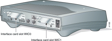
Figure 1-9 illustrates a Cisco 1750 router, showing the WAN interface card slots and the voice interface card slot.
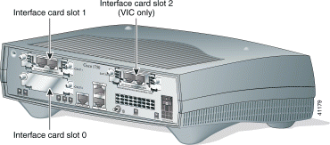
Table 1-3 lists WAN interface card options available for the Cisco 1700 series routers with their minimum software requirements for Cisco IOS releases.
| WAN Interface Card | IOS Release 12.0 | IOS Release 12.1 | IOS Release 12.2 |
|---|---|---|---|
1-Port Serial (WIC-1T) | 12.0(1)XA3 | 12.1(5)T | 12.2(1)T |
2-Port Serial (WIC-2T) | 12.0(1)XA3 | 12.1(5)T | 12.2(1)T |
2-Port Asynchronous/Synchronous Serial (WIC-2A/S) | 12.0(1)XA3 | 12.1(5)T | 12.2(1)T |
1-Port ISDN BRI S/T (WIC-1B-S/T) | 12.0(1)XA3 | 12.1(5)T | 12.2(1)T |
1-Port ISDN BRI U | 12.0(1)XA3 | 12.1(5)T | 12.2(1)T |
1-Port 56/64-kbps DSU/CSU (WIC-1DSU-56K4) | 12.0(1)XA3 | 12.1(5)T | 12.2(1)T |
1-Port T1/FT1 (WIC-1DSU-T1) | 12.0(1)XA3 | 12.1(5)T | 12.2(1)T |
1-Port ADSL (WIC-1ADSL) |
|
| 12.2(1)T |
2-Port ISDN BRI Voice Interface (VIC-2BRI-NT/TE) |
| 12.1(5)Xx | 12.2(1)T |
2-Port E&M voice/fax interface (VIC-2E/M) |
| 12.1(5)T | 12.2(1)T |
The following table replaces Table 1-6 on page 1-27 and adds the 2-Port VIC2-DID voice interface card.
| Interface | Connecting Method | Ringer Equivalence Number |
|---|---|---|
VIC-2FXO loop-start trunk interface | CA11, CA48 | 0.5 |
VIC-2FXO ground-start trunk interface | CA11, CA48 | 0.5 |
VIC-2FXS on-premises station interface | CA11, CA48 | 0.5 |
VIC-2E/M on-premises E&M interface | CA11, CA48 | 0.5 |
VIC-2BRI-S/T on-premises BRI interface | CB-1B | 0.0 |
VIC-2BRI-NT/TE on-premises BRI interface | CB-1B | 0.0 |
VIC-2DID voice interface | CA11A, CA14A | 0.5 |
The information in this section supplements or corrects the information in Chapter 2, "Installing WAN and Voice Interface Cards in Cisco Modular Routers."
This section replaces the "Installing a WAN Interface Card in a Cisco 1700 Series or Cisco 1600 Series Router" section.
This section describes how to install a WAN interface card (WIC) and voice interface card (VIC) in a Cisco 1700 series router or Cisco 1600 series router.
To install a WAN interface card in a Cisco 3600 series or Cisco 2600 series router, see the "Installing a Network Module in a Cisco 3600 Series or Cisco 2600 Series Router" section or the "Before Installing a Voice Interface Card" section in Chapter 2.
The Cisco 1700 series routers have two slots for installing WAN interface cards. On the Cisco 1720 routers, the slots numbered WIC0 are on the left, and the slots numbered WIC1 are on the right. (See Figure 2-6.) On the Cisco 1750 routers, the slots numbered WIC/VIC0 are on the bottom and WIC/VIC1 are on the top. (See Figure 2-7.) In addition, the Cisco 1750 routers have a VIC-only slot 2 on the top right. (See Figure 2-7.)
If you are installing a single WAN interface card in a Cisco 1720 router, install the card in the WIC0 slot. A single card installed in WIC1 could affect your router configuration.
If you are installing a WAN interface card on the Cisco 1750 router, you can install the card in either WIC/VIC slot 0 or WIC/VIC slot 1.


 |
TimeSaver You can install WAN and voice interface cards either before or after mounting the router, whichever is more convenient. |
 |
Caution WAN and voice interface cards do not support online insertion and removal (hot swapping). Before inserting a WAN or voice interface card into the router chassis, you must turn off electrical power and disconnect network cables. |
 |
Note The figures in this section show a Cisco 1600 series router, but the installation sequence described applies to both the Cisco 1600 series and Cisco 1700 series routers. |
Follow this procedure to install the WAN or voice interface card in the router:
On Cisco 1600 series router, turn off power to the router. However, to channel ESD voltages to ground, do not unplug the power cable.
Step 2 Remove all network interface cables, including telephone cables, from the rear panel.
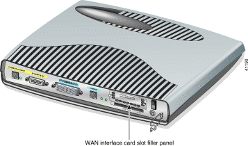
Step 3 Use either a number-2 Phillips screwdriver or a small flat-blade screwdriver to remove the filler panel from the WAN interface card slot. (See Figure 2-8.) Save the filler panel for future use.
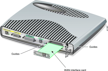
Step 4 Align the card with the guides and slide it gently into the WAN interface card slot. (See Figure 2-9.)
Step 5 Push the card into place until you feel its edge connector mate securely with the connector in the router chassis.
Step 6 Fasten the card captive mounting screws into the chassis by using the Phillips or flat-blade screwdriver.
 |
Note If any WAN or voice interface card slot on the chassis is unoccupied, install a filler panel to enable proper airflow. |
Step 7 If the router was previously running, reinstall the network interface cables, and turn on power to the router.
After installing the WAN interface card into the router, proceed to Chapter 3, "Connecting WAN and Voice Interface Cards to a Network."
The information in this section supplements the information in Chapter 3, "Connecting WAN and Voice Interface Cards to a Network." The following sections are updated:
The 1-port digital subscriber line (DSL) WAN interface cards support one Asymmetric DSL (ADSL) line between a single customer premises equipment (CPE) subscriber and the central office.
 |
Note The ADSL WAN interface card can be used with NM-FE2W, NM-1FE1R-2W, 2W, and 2FE2W network modules. ADSL WICs will not work in older combo network modules. |
Use a straight-through RJ-11 cable for this connection.
 |
Note The port on this interface card is color-coded lavender. |
 |
Note If you are connecting a DSL card to an RJ-11 wall jack that has the DSL pair wired for pins 2 and 5, you must use an RJ-11 craossover cable (lavender with blue stripe). The RJ-11 crossover cable is orderable separately as a spare. |
Complete the following steps to connect a 1-port ADSL card to the network.
Step 2 Connect one end of the cable to the ADSL port on the card.
Step 3 Connect the other end to the wall jack (RJ-11) at your site, as shown in Figure 3-22.
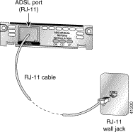
Step 4 Turn on power to the router.
Step 5 To connect the card to the network, you must configure the ADSL card in the router to the no shutdown state. Enter the no shut command in the router configuration. Check that the CD LED goes on, indicating that the card is connected to the network.
The ADSL cards have three LEDs, which are shown in Figure 3-23 and described in Table 3-6.

| Feature | Color | Description |
|---|---|---|
CD LED | Green | The unit is connected to the network. On during normal operation. |
LP LED | Yellow | DSL interface is in loopback mode. |
| Off | Normal operation. |
OK LED | Green | Enabled when the card is detected by the router. |
Table 3-7 shows the ADSL card pinouts.
| Pin | Signal |
|---|---|
3 | Tip |
4 | Ring |
If you have additional cards to install, proceed to the appropriate sections in this manual. When you have finished all installations, see the software configuration guide that shipped with your hardware.
This information is added to the "Voice Interface Cards" section.
The VIC-2DID card is suitable for exposed plant lead connection. However, it requires the host router chassis to have a permanent protective earth connection. Make sure that a permanent earth connection is in place before installing the card. A grounding kit is provided with each voice network module and with each chassis configured with voice network modules. Install the kit in accordance with the guide, Installing the Grounding Lug on Cisco 2600 and Cisco 3600 Series Routers.
If you find a router chassis without a permanent earth connection and yourself without a grounding kit, take one of the following actions:
This product in not intended for Scandinavian countries.
This section replaces the "2-Port ISDN BRI Card" subsection in the "Voice Interface Cards" section.
There are two 2-Port ISDN BRI voice interface cards for the Cisco 2600 series and Cisco 3600 series routers.
The ISDN BRI S/T voice interface card provides a client-side (TE) ISDN S/T physical interface for connection to an NT1 terminating an ISDN telephone network. Each of its two ports can carry two voice calls (one over each ISDN B channel), for a total of four calls per ISDN BRI card.
The ISDN BRI NT/TE voice interface card has the same capabilities as the S/T card, but can also be configured to provide a network termination (NT) interface with phantom power.
The card is illustrated in Figure 3-31.

To use all four voice channels, you must install the ISDN BRI card in slot 0 of a two-slot voice network module (Cisco part number NM-2V). Slot 1 should remain empty.
 |
Note If slot 0 is unoccupied, the system treats it as a pair of analog voice ports. |
If you install any of the following configurations, the Cisco IOS software disables certain ports, as shown in Table 3-8:
| Network Module | Slot | Voice Interface Card | Port | Status |
|---|---|---|---|---|
NM-1V | 0 | VIC-2BRI-S/T-TE, | 0 | Up |
|
|
| 1 | Down |
NM-2V | 0 | VIC-2BRI-S/T-TE, | 0 | Up |
|
|
| 1 | Up |
NM-2V | 0 | VIC-2BRI-S/T-TE, | 0 | Up |
|
|
| 1 | Up |
| 1 | VIC-2BRI-S/T-TE, | 0 | Down |
|
|
| 1 | Down |
NM-2V | 0 | VIC-2BRI-S/T-TE, | 0 | Up |
|
|
| 1 | Up |
| 1 | Analog voice interface card | 0 | Down |
|
|
| 1 | Down |
NM-2V | 0 | Analog voice interface card | 0 | Up |
|
|
| 1 | Up |
| 1 | VIC-2BRI-S/T-TE, | 0 | Up |
|
|
| 1 | Down |
Use the straight-through RJ-48C cable to connect the two-port ISDN BRI card to the ISDN network through a telephone wall outlet or other device.
 |
Caution To prevent damage to the router, be sure to connect the BRI cable to the BRI connector only, and not to any other RJ-48C connector. |
To connect the two-port ISDN BRI card to the router, follow these steps:
Step 2 Connect one end of a straight-through RJ-48C-to-RJ-48C cable to the card RJ-48C port. (See Figure 3-32.)
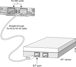
 |
Note When the interface is configured as NT and is connecting to a TE device, the cable must have the transmit and receive pins swapped (crossover cable). (See Table 3-9.) |
| ISDN BRI NT/TE | NT Interface (use straight-through cable) | TE Interface (use crossover cable) |
|---|---|---|
Pin 3/T+ | Pin 3/R+ | Pin 3/T+ |
Pin 4/R+ | Pin 4/T+ | Pin 4/R+ |
Pin 5/R- | Pin 5/T- | Pin 5/R- |
Pin 6/T- | Pin 6/R- | Pin 6/T- |
Step 3 Connect the other end to the RJ-48C wall outlet or other device.
ISDN BRI voice interface cards have three LEDs, as listed in Table 3-10.
| LED | Meaning |
|---|---|
B1 | Call active on B1 channel |
B2 | Call active on B2 channel |
OK | Interface is connected to an ISDN network |
If you have additional cards to install, proceed to the appropriate sections in this manual. When you have finished all installations, see the software configuration guide that shipped with your hardware.
A Direct Inward Dial (DID) voice interface enables a Cisco 2600 series or Cisco 3600 series router to provide DID service to extensions on a PBX. Figure 3-33 shows the VIC-2DID card.

Use a standard RJ-11 modular telephone cable to connect the VIC-2DID card to the PSTN or PBX.
Step 2 Confirm that the router is still turned off.
Step 3 Connect one end of the cable to an RJ-11 port on the card. (See Figure 3-34.)
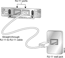
Step 4 Connect the other end of the cable to a telephone wall outlet or to a PBX.
 |
Caution The VIC-2DID card may be damaged if connected to a standard PSTN line. Ensure that lines to the PSTN are provisioned for DID. |
The following sections provide sources for obtaining documentation from Cisco Systems.
You can access the most current Cisco documentation on the World Wide Web at the following sites:
Cisco documentation and additional literature are available in a CD-ROM package, which ships with your product. The Documentation CD-ROM is updated monthly and may be more current than printed documentation. The CD-ROM package is available as a single unit or as an annual subscription.
Cisco documentation is available in the following ways:
If you are reading Cisco product documentation on the World Wide Web, you can submit technical comments electronically. Click Feedback in the toolbar and select Documentation. After you complete the form, click Submit to send it to Cisco.
You can e-mail your comments to bug-doc@cisco.com.
To submit your comments by mail, use the response card behind the front cover of your document, or write to the following address:
Attn Document Resource Connection
Cisco Systems, Inc.
170 West Tasman Drive
San Jose, CA 95134-9883
We appreciate your comments.
Cisco provides Cisco.com as a starting point for all technical assistance. Customers and partners can obtain documentation, troubleshooting tips, and sample configurations from online tools. For Cisco.com registered users, additional troubleshooting tools are available from the TAC website.
Cisco.com is the foundation of a suite of interactive, networked services that provides immediate, open access to Cisco information and resources at anytime, from anywhere in the world. This highly integrated Internet application is a powerful, easy-to-use tool for doing business with Cisco.
Cisco.com provides a broad range of features and services to help customers and partners streamline business processes and improve productivity. Through Cisco.com, you can find information about Cisco and our networking solutions, services, and programs. In addition, you can resolve technical issues with online technical support, download and test software packages, and order Cisco learning materials and merchandise. Valuable online skill assessment, training, and certification programs are also available.
Customers and partners can self-register on Cisco.com to obtain additional personalized information and services. Registered users can order products, check on the status of an order, access technical support, and view benefits specific to their relationships with Cisco.
To access Cisco.com, go to the following website:
The Cisco TAC website is available to all customers who need technical assistance with a Cisco product or technology that is under warranty or covered by a maintenance contract.
If you have a priority level 3 (P3) or priority level 4 (P4) problem, contact TAC by going to the TAC website:
P3 and P4 level problems are defined as follows:
In each of the above cases, use the Cisco TAC website to quickly find answers to your questions.
To register for Cisco.com, go to the following website:
http://www.cisco.com/register/
If you cannot resolve your technical issue by using the TAC online resources, Cisco.com registered users can open a case online by using the TAC Case Open tool at the following website:
http://www.cisco.com/tac/caseopen
If you have a priority level 1(P1) or priority level 2 (P2) problem, contact TAC by telephone and immediately open a case. To obtain a directory of toll-free numbers for your country, go to the following website:
http://www.cisco.com/warp/public/687/Directory/DirTAC.shtml
P1 and P2 level problems are defined as follows:

![]()
![]()
![]()
![]()
![]()
![]()
![]()
![]()
Posted: Mon Sep 24 18:32:07 PDT 2001
All contents are Copyright © 1992--2001 Cisco Systems, Inc. All rights reserved.
Important Notices and Privacy Statement.