|
|

Table Of Contents
Connecting Cisco Wireless LAN Controller Modules
Cisco Wireless LAN Controller Modules
Cisco Wireless LAN Controller Module LEDs
Connecting Cisco Wireless LAN Controller Modules to the Network
Online Insertion and Removal with a Cisco Wireless LAN Controller Module
Replacing the Cisco WLAN Controller Module
Configuring the Replacement WLAN Controller Module
Cisco IOS Software Documentation
Cisco Wireless LAN Controller Module Documentation
Connecting Cisco Wireless LAN Controller Modules
This chapter describes how to connect Cisco wireless LAN (WLAN) controller modules (WLCM) and contains the following sections:
•
Cisco Wireless LAN Controller Modules
•
•
The Cisco wireless LAN (WLAN) controller module is designed to provide small and medium-sized businesses (SMBs) and enterprise branch office customers 802.11 wireless networking solutions for Cisco 2800 and Cisco 3800 series integrated services routers (ISRs) and Cisco 3700 series routers.
Note
Tip
Cisco WLAN controller modules ship with and boot from an installed 256-MB CompactFlash (CF) memory card. The CompactFlash memory card contains the boot loader, Linux kernel, Cisco WLAN controller module and access points executable file, and Cisco WLAN controller module configuration.
Note
Note
http://www.cisco.com/en/US/products/ps6305/products_configuration_guide_book09186a00804f988b.html
Cisco Wireless LAN Controller Modules
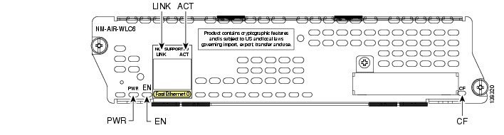
Figure 31-1 shows the faceplate of the Cisco WLAN controller module.
Note
Figure 31-1 Cisco Wireless LAN Controller Module Faceplate
Note
Cisco Wireless LAN Controller Module LEDs
Table 31-1 lists the Cisco wireless LAN controller module LEDs and their meanings.
Connecting Cisco Wireless LAN Controller Modules to the Network
The Cisco wireless LAN controller module connects to the network through internal connections within the router and requires no additional cables for network connectivity.
Online Insertion and Removal with a Cisco Wireless LAN Controller Module
The Cisco integrated services routers (ISRs) allow you to replace network modules without switching off the router or affecting the operation of other interfaces. This feature is called online insertion and removal (OIR). OIR of network modules provides uninterrupted operation to network users, maintains routing information, and ensures session preservation.
Note
Tip
For a description of informational and error messages that may appear on the console during this procedure, see the hardware installation guide for your type of router.
Saving the Configuration File
This configuration assumes a configuration file already exists on the Cisco WLAN controller module CompactFlash memory card. To save the configuration file, follow these steps with the router in privileged EXEC mode.
Step 1
Router# service-module wlan-controller 1/0 sessionTrying 192.0.2.254, 2066 ... OpenStep 2
(WLAN-Controller) > transfer upload serverip 192.0.2.24Step 3
(WLAN-Controller) > transfer upload datatype configurationStep 4
(WLAN-Controller) > transfer upload filename <config-running.bin>Step 5
(WLAN-Controller) > transfer upload startMode............................................. TFTPTFTP Server IP................................... 192.0.2.24TFTP Path........................................ /TFTP Filename.................................... config.binData Type........................................ Config FileEncryption....................................... Disabled***************************************************** WARNING: Config File Encryption Disabled *****************************************************Are you sure you want to start? (y/n) yTftp Config transfer starting.File transfer operation completed successfully.(WLAN-Controller) >Step 6
Step 7
Router# disconnectClosing connection to 192.0.2.254 [confirm]Router#Step 8
Router# service-module wlan-controller 1/0 session clear[confirm][OK]Router#[Resuming connection 1 to 192.0.2.254 ... ][Connection to 192.0.2.254 closed by foreign host]Router#Step 9
Router (config)# interface wlan-controller 1/0Router (config-if)# shutdownRouter (config-if)# exitReplacing the Cisco WLAN Controller Module
Follow these steps to remove and replace the Cisco WLAN controller module.
Step 1
Step 2
Step 3
Step 4
Step 5
Note
Configuring the Replacement WLAN Controller Module
Follow these steps to configure the replacement Cisco WLAN controller module.
Step 1
Router# service-module wlan-controller 1/0 resetUse reset only to recover from shutdown or failed stateWarning: May lose data on the hard disc!Do you want to reset?[confirm]Trying to reset Service Module wlan-controller1/0.Step 2
Router# configure terminalEnter configuration commands, one per line. End with CNTL/Z.Router(config)# interface wlan-controller 1/0Router(config-if)# ip address 192.0.2.254 255.255.255.0Router(config-if)# no shutdownRouter(config-if)# endRouter#Router#Step 3
Note
http://www.cisco.com/en/US/products/ps6305/products_configuration_guide_book09186a00804f988b.htmlRouter# service-module wlan-controller slot/unit sessionTrying 192.0.2.254, 2066 ... OpenCisco Bootloader (Version 3.2.10.0)Booting Primary Image...Press <ESC> now for additional boot options...Detecting hardware . . . .Cisco is a trademark of Cisco Systems, Inc.Software Copyright Cisco Systems, Inc. All rights reserved.Cisco AireOS Version 3.2.10.0Initializing OS Services: okInitializing Serial Services: okInitializing Network Services: ok...Web Server: okCLI: okSecure Web: ok(WLAN-Controller)Enter User Name (or 'Recover-Config' to reset configuration to factory defaults)Step 4
User: adminPassword: *****(WLAN-Controller) >Step 5
(WLAN-Controller) > transfer download serverip 192.0.2.24Step 6
(WLAN-Controller) > transfer download datatype configurationStep 7
(WLAN-Controller) > transfer download filename <config-running.bin>Step 8
(WLAN-Controller) > transfer download startMode............................................. TFTPTFTP Server IP................................... 192.0.2.24TFTP Path........................................ /TFTP Filename.................................... config-running.binData Type........................................ Config FileEncryption....................................... Disabled***************************************************** WARNING: Config File Encryption Disabled *****************************************************Are you sure you want to start? (y/n) yTftp Config transfer starting.File transfer operation completed successfully.(WLAN-Controller) >
Note
Related Documents
For additional information, see the following documents.
Tip
Hardware Documentation
For general information on installing and removing Cisco modules, see the Cisco Network Modules Hardware Installation Guide (this document).
Cisco IOS Software Documentation
For a description of the Cisco IOS features supported on Cisco wireless LAN controller modules, see the "Cisco IOS Software Documentation" section on page 1-31.
Cisco Wireless LAN Controller Module Documentation
For additional information about WLAN support on the Cisco wireless LAN controller module, see the wireless support resources documentation at the following URL:
http://www.cisco.com/en/US/products/hw/wireless/tsd_products_support_category_home.html
![]()
![]()
![]()
![]()
![]()
![]()
![]()
![]()
Posted: Fri Dec 14 12:10:31 PST 2007
All contents are Copyright © 1992--2007 Cisco Systems, Inc. All rights reserved.
Important Notices and Privacy Statement.