|
|

This appendix provides instructions for mounting the Cisco IGS on a wall or in an equipment rack with the optional Rack/Wall Mount and Slide Assembly kit, Cisco Part Number COM-RKI. The IGS can be mounted on a wall to save space in small wiring closets or in areas with limited rack space. The rack-mounting kit includes slides, which allow access to the IGS rear panel without having to disconnect cables or remove the unit from the rack. The rack mount is designed for use in standard 19-inch racks. This appendix describes the following:
Before beginning installation, verify that you received all parts listed in the section entitled, "List of Parts."
The following tools are required for this procedure:
For wall mounting only: The bracket mounting points are not wide enough to accommodate the 16" x 16" spacing commonly used for wall studs. We recommend mounting a piece of plywood (minimum 18 x 18 x 1/2) on the wall first, then mounting the bracket to the plywood. Otherwise, install the bracket along a vertical or horizontal stud to ensure that it is anchored to solid wood in at least two places.
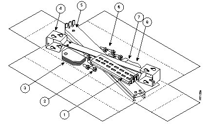
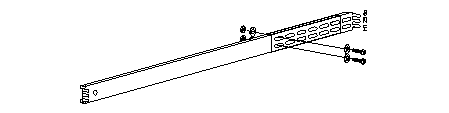
Before beginning this procedure, verify that you have all of the following parts, which are illustrated in Figure C-1:
1. Wood screws, type A #10 x 1" (4)
2. 10-32 x 0.5" slotted oval head screws with steel cup washers (2 bags, 4 sets/bag)
3. Spacers (8)
4. Rack/wall brackets (2)
5. Slide bar assemblies (inner, middle, and outer slide) (1 pair)
6. Extenders (2)
7. 4-40 x 1/4" screws (7)
8. 10-32 x 0.38" binding head mounting screws with hex nuts (8 ea) (not shown in illustration)
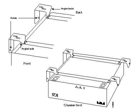
A mounting bracket, which is used for both wall- and rack-mounting, is installed onto the bottom of the IGS chassis. Refer to Figure C-2, Figure C-3, and Figure C-4 while performing the steps beginning on page C-4.
 |
Step 1: Turn the IGS power switch off, and remove all cables from the back of the IGS chassis, including the power cable.
Step 2: Turn the chassis upside down, and place it on a sturdy, level working surface.
Step 3: Remove the feet. Remove the screw in the center of each rubber foot (see Figure C-2), then pull the feet out. Discard the screws and the rubber feet.
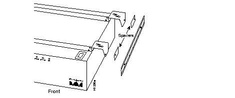
Step 4: Place the brackets across the chassis in the orientation shown in Figure C-3, and secure them with seven 4-40 x 1/4" screws. Do not install spacers at this time.
Choose the wall on which you will mount the IGS. When choosing a position, be sure to consider cable lengths and limitations, and wall structure.
Step 5: Position the IGS chassis against the wall, as shown in Figure C-4. Use the lower of each pair of keyhole cutouts to mark the drilling points.
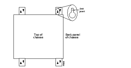
Step 6: Drill the four points, and install #10 x 1" wood screws directly into the wall. Leave a 1/8-inch gap between the wall and the bottom of the screw head.
Step 7: Place the chassis over the screws and slide it down 1/4 inch. Tighten the screws.
Step 8: Attach the appropriate cables to the rear of the unit.
The rack-mounting kit includes slides, which allow you to remove the chassis cover and access the system card for memory or EPROM upgrades.
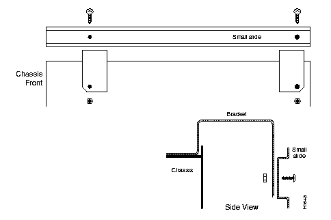
Step 1: Remove the smallest, inner-most slide from both slide assemblies. Use four 10-32 x 0.38" binding head mounting screws and four hex nuts to secure the small slides to the brackets (Figure C-5).
Step 2: Slide the extenders over the flat ends of the slide assemblies, and adjust the length to the approximate rack depth (see Figure C-6). Secure the extenders with four 10-32 x 0.38" binding head mounting screws and four hex nuts.
Step 3: Place the slide assemblies inside the rack as shown in Figure C-7. Adjust the length, if necessary, at the extender. Use eight 10-32 x 0.5-inch oval head screws and eight steel cup washers to secure the slide assemblies to the mounting strips (four each slide assembly, two each front and back).
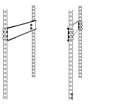
Step 4: Slide the chassis slides into the slide assemblies in the rack. Slowly and firmly push the chassis all the way into the rack. You will hear the slides click into place. If the chassis slides do not fit in the rack slides, do not force them (see the Note below).
Step 5: If spacers are necessary, install spacers between the brackets and small slides, as shown in Figure C-8. Up to eight spacers (four per side) can be installed.
|
|