|
|

This chapter describes the procedures for setting the jumpers and installing the AccessPro PC card in your PC. This chapter contains the following sections:
To install the AccessPro card, you need a screwdriver for the rear panel of your PC.
The AccessPro card is simple to install. The jumpers on the card are factory set to their default settings and in most cases will not need to be changed.
Verify that the jumpers are set correctly by referring to Figure 3-1 for Model AP-EC and Model AP-EBC, or to Figure 3-2 for Model AP-RC and Model AP-RBC.
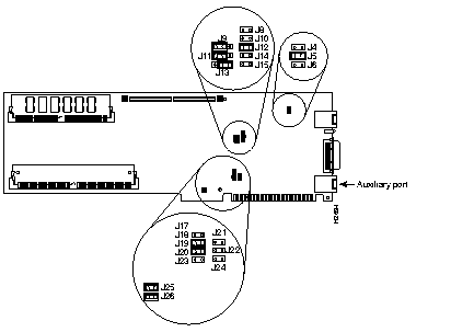
Configure ports by setting the jumpers on the AccessPro card. These jumpers select the communications port (COMport), and the interrupt request line (IRQ) used by the COMport.
Because the AccessPro card uses a COMport for its console, you must verify that the COMport and the IRQ are correctly set for your PC system.
Although the PC has four COMports, and each port has its own I/O address, the PC standard requires that they share IRQs. The standard PC assignments for COMports, their I/O addresses, and IRQ settings are given in Table 3-1.
| COMport | I/O Address | IRQ |
|---|---|---|
| 1 | $3F8 to $3FF | 4 |
| 2 | $2F8 to $2FF | 3 |
| 3 | $3E8 to $3EF | 4 |
| 4 | $2E8 to $2EF | 3 |
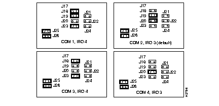
The default COMport (COM 2) is selected by setting jumper J18 to open (the jumper is removed) and setting J19 to closed (the jumper is installed). This setting will work in most systems where there is a serial mouse or another device using COM 1. If there is no conflict on your PC, then your AccessPro card can be installed as configured at the factory.
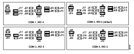
The IRQ is set using jumpers J20 and J23. (See Figure 3-3 and Figure 3-4.) The default IRQ setting (IRQ 3) is selected by setting J20 to closed (the jumper is installed) and J23 to open (the jumper is removed).
If you have additional cards, or built-in interfaces on your PC motherboard that use internal COMports, the settings on your AccessPro card may need to be modified.
You need to know what COMports and IRQs are in use by the pre-existing cards to determine if there are potential conflicts with the AccessPro card. For example, if you have a device in the PC that uses COM 4, then the AccessPro card cannot use the default setting of COM 2. The AccessPro card must be set to COM 1 or COM 3 because there is a conflict on the IRQ with the device using COM 2.
Figure 3-3 illustrates how to set the different combinations of COMports and IRQs for the Ethernet AccessPro card. Figure 3-4 illustrates how to set the different combinations of COMports and IRQs for the Token Ring AccessPro card.
To determine if there is a conflict between the default settings on your AccessPro card and your PC, you can do one of the following:
For additional information on setting the COMport jumpers, see the chapter "Maintaining the AccessPro PC Card."
The AccessPro card is a standard ISA-bus PC card and is installed just like any other PC card. The entire installation procedure requires a number 1 Phillips screwdriver (or whatever type of screwdriver is appropriate for the screws on the rear panel of your PC).
Following is the procedure for installing the AccessPro card:
Step 1 Turn OFF the power to the PC but, to channel ESD voltages to ground, do not unplug it.
Step 2 Attach an ESD-preventive wrist strap and make certain that the PC chassis is properly grounded.
Step 3 Remove the cover from your PC following the instructions provided by the PC manufacturer.
Step 4 Remove the system-code SIMMs from their ESD-protective bag, which is located in the installation kit. Install the system-code SIMMs according to the directions in the chapter "Maintaining the AccessPro PC Card."
Step 5 In some cases, additional memory must be installed on the AccessPro card. Additional memory is required if you have selected more than the IP Routing feature set. Feature sets requiring additional DRAM are as follows:
If you order a card with one of the feature sets listed above, an additional ESD-protective bag containing DRAM SIMMs will be included in the installation kit. Remove the DRAM SIMMs from the bag and install them on the AccessPro card according to the instructions in the chapter "Maintaining the AccessPro PC Card."
Step 6 Determine which ISA-bus slot or slots (two slots are required to install Model AP-EBC or Model AP-RBC) you will use for the AccessPro card. You can use any empty slots.
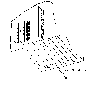
Step 7 Remove the screw(s) from the appropriate blank filler plate (from two plates if you are installing Model AP-EBC or Model AP-RBC) in the rear panel of the PC and set the screw(s) aside. (See Figure 3-5.)
Step 8 Install the AccessPro card in its PC slot. (See Figure 3-6.)
Step 9 Using the screw(s) that you removed from the blank filler plate, fasten the AccessPro card to the rear panel of the PC. (See Figure 3-6.) To prevent stripping threads, do not overtighten the screw(s).
Step 10 Replace the PC cover following the instructions provided by the PC manufacturer.
After installing the AccessPro card in your PC, you need to verify that the COMport and IRQ selections you made are correct. To do this, you need to run a terminal emulation program on the PC.
Set the terminal emulation program to the following serial port configuration parameters:
Make sure that your terminal emulation software is configured to be the same COMport address and IRQ that you selected before you installed the AccessPro card in the PC. Consult the documentation for your terminal emulation program to find out how to make the required configuration changes to address the COMport and IRQ that you configured on the AccessPro card.
If the emulation is properly configured, you will be able to communicate with the AccessPro card.
After booting to the monitor prompt (>), prepare the AccessPro card for network connections (see the following section "Making Network Connections"). If the PC needs to be moved to a different location for connection to a WAN, turn it off now and move it before continuing with the installation.
After you have installed the AccessPro card in your PC, you need to connect the card to your LAN (Ethernet or Token Ring) and WAN (serial, ISDN BRI, or both). Complete the following steps to connect the external cables on the rear panel of the AccessPro card.
If your card has an Ethernet port (Model AP-EC and Model AP-EBC), start with Step 1. If your card has a Token Ring port (Model AP-RC and Model AP-RBC), start with Step 2.
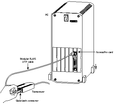
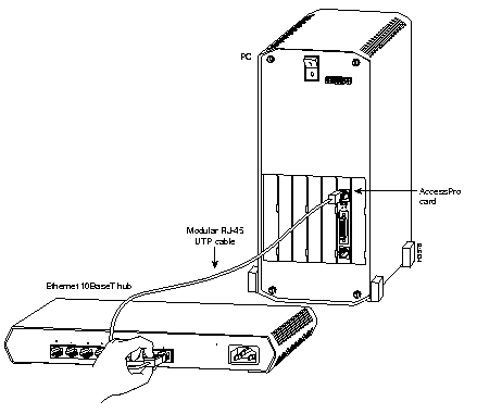
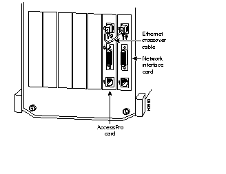
Step 1 Use a modular RJ-45 UTP cable to connect the Ethernet port directly to a transceiver, as shown in Figure 3-7, or to an Ethernet 10BaseT hub, as shown in Figure 3-8. If you are not using a hub or a transceiver, you can connect the Ethernet port to the PC's network interface card, as shown in Figure 3-9. Proceed to Step 3.
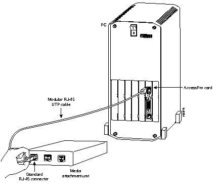
Step 2 Use a modular RJ-45 UTP cable to connect the Token Ring port to a media attachment unit (MAU), as shown in Figure 3-10.
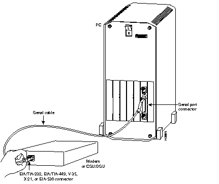
Step 3 Use a special serial cable to connect the serial port to the modem or CSU/DSU, as shown in Figure 3-11. This cable is available from us and is usually ordered with the system. The cable uses a DB-60 connector on the chassis end. For cable specifications, see the appendix "Cabling Specifications." For ordering information, contact a customer service representative.
All serial interfaces except the EIA-530 interface can be configured as data communications equipment (DCE) using a DCE cable. The DTE serial port needs external clocking, which is provided by a CSU/DSU or modem.
 | Warning Hazardous network voltages are present in the BRI cable. If you detach the BRI cable, detach the end away from the AccessPro card first to avoid possible electric shock. Network hazardous voltages also are present on the system card in the area of the BRI port (RJ-45 connector), regardless of when power is turned off. (See Figure 3-12.) (To see translated versions of this warning, refer to the appendix "Translated Safety Warnings.") |

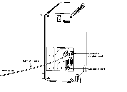
Step 4 Use the appropriate cable to connect the BRI port on Model AP-EBC and Model AP-RBC to the ISDN line through the NT1, as shown in Figure 3-13.
After making your network connections, you are ready to configure the AccessPro card. (See the chapter "Configuring the AccessPro PC Card.")
|
|