|
|

Table Of Contents
Installing and Configuring Cisco 802 IDSL and Cisco 804 IDSL Routers
Preventing Electrostatic Discharge Damage
Connecting Cables to the Router
Connecting a Server, PC, or Workstation
Example of Basic Configuration Output
IDSL Configuration with Frame Relay
Example of Frame Relay Configuration Output
Troubleshooting Using Debug Commands
Output 1 Example (show isdn status)
Output 2 Example (debug ppp negotiation and debug ppp authentication)
Cisco Product Security Overview
Reporting Security Problems in Cisco Products
Obtaining Technical Assistance
Cisco Technical Support Website
Definitions of Service Request Severity
Obtaining Additional Publications and Information
Installing and Configuring Cisco 802 IDSL and Cisco 804 IDSL Routers
Overview
Cisco 802 IDSL and Cisco 804 IDSL routers offer high-speed digital connections using an ISDN line and support line rates up to 144 kilobits per second (kbps). Integrated Services Digital Network (ISDN) Digital Subscriber Line (IDSL) expands DSL connectivity for customers who are outside the Service Provider's range for DSL or for those who are unable to qualify for DSL connections.
This document describes the setup and configuration of your routers and contains the following sections:
•
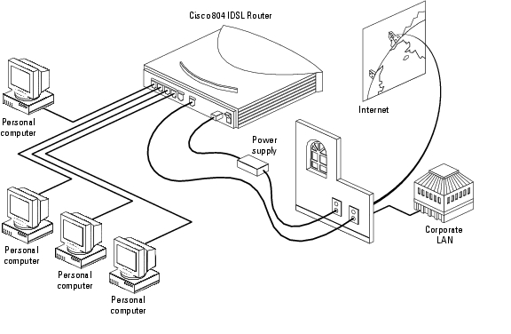
Connecting Cables to the Router
The following figure shows a typical setup of the Cisco 804 IDSL router.
Before You Start
Before you begin installing your Cisco IDSL router, read the following topics:
•
•
Safety
Before installing the router, read the following warnings:
.
Warning
Warning
Warning
Warning
Warning
Warning
Warning
Warning
) appears above a port, you must not connect the port to a public network that follows the European Union standards. Connecting the port to this type of public network can cause severe personal injury or can damage the unit. Statement 1031
Preventing Electrostatic Discharge Damage
Electrostatic discharge (ESD) is a transfer of electrostatic charge between bodies of different electrostatic potentials, such as an operator and a piece of electrical equipment. It occurs when electronic components are improperly handled, and it can damage equipment and impair electrical circuitry. Electrostatic discharge is more likely to occur with the combination of synthetic fibers and dry atmosphere.
Step 1
Step 2
Connect the clip to an unpainted surface of the chassis frame to safely channel unwanted ESD voltages to ground. To properly guard against ESD damage and shocks, the wrist strap and cord must operate effectively. If no wrist strap is available, ground yourself by touching the metal part of the chassis. Always follow the guidelines in the preceding section, " Safety."
Step 3
If cables are connected at one end only, do not touch the exposed pins at the unconnected end of the cable.
Note
Caution
Preventing Router Damage
Use the following guidelines when connecting devices to your router:
•
•
) appears above a port, you can connect the port directly to a public network that follows the European Union standards.
Unpacking the Router
Your router package should include the following items:
Connecting Cables to the Router
The following figures show the router ports. These ports and the cables are color-coded to help you connect the cables correctly.
For more information, see the following subsections:
•
•
•
Connecting an Ethernet Device
This section describes how to connect a hub, server, PC, or workstation with a 10- or 10/100-Mbps network interface card (NIC).
Before connecting an Ethernet device, you need to know the following:
•
•
Caution
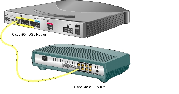
Connecting a Hub
Step 1
•
•
Step 2
Step 3
•
•
Step 4
•
•
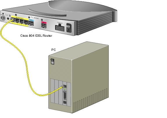
Connecting a Server, PC, or Workstation
Connect the yellow cable to one of the following ports:
•
•
Step 1
Step 2
•
•
Step 3
Step 4
Connecting an IDSL Line
Caution
Step 1
Step 2
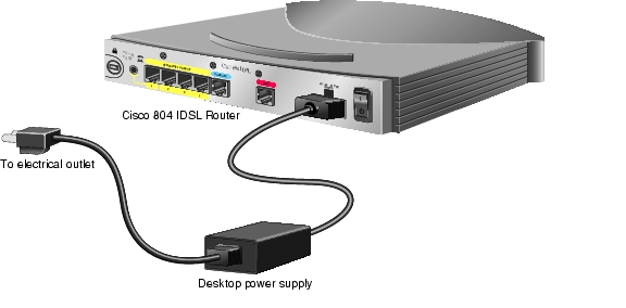
Connecting the Power Supply
Step 1
).
Step 2
Step 3
Step 4
Step 5
Verifying Router Connections
Verify the power connection and all other connections (links) by checking the LEDs in the table below. If the LEDs are not on, see the troubleshooting information in the Cisco 800 Series Routers Hardware Installation Guide.
Configuring the IDSL Router
You can configure your Cisco IDSL router using the Cisco IOS command-line interface or the Cisco 800 Fast Step application. For information about using Cisco 800 Fast Step, refer to the Cisco 800 DSL Connection Kit document in the product accessory kit or on Cisco Connection Online (CCO).
The following procedures are examples of how to configure the Cisco IDSL router using Cisco IOS commands. For more information about Cisco IOS commands, refer to the Cisco IOS documentation set on Cisco.com.
Basic IDSL Configuration
The following is an example of a typical IDSL configuration.
Step 1
router(config)# hostname 802Step 2
router(config)# username isp password ciscoStep 3
router(config)# isdn switch-type basic-5essStep 4
router(config)# isdn leased-line bri0 128Step 5
router(config)# ip dhcp pool DHCPpoolLAN_0Step 6
router(dhcp-config)# network 192.168.1.0 255.255.255.0Step 7
router(dhcp-config)# dns-server 172.29.20.41 172.29.20.51Step 8
router(dhcp-config)# netbios-name-server 172.29.20.41 172.29.20.51Step 9
router(dhcp-config)# default-router 192.168.1.1Step 10
router(dhcp-config)# exitrouter(config)#Step 11
router(config)# ip name-server 172.29.20.41router(config)# ip name-server 172.29.20.51Step 12
router(config)# interface ethernet0router(config-if)#Step 13
router(config-if)# ip address 192.168.1.1 255.255.255.0Step 14
router(config-if)# ip nat insideStep 15
router(config-if)# interface bri0router(config-if)# ip address negotiatedStep 16
router(config-if)# encapsulation pppStep 17
router(config-if)# ppp authentication chapStep 18
router(config-if)# ip nat outsideStep 19
router(config-if)# ppp chap hostname 802router(config-if)# ppp chap password ciscoStep 20
router(config-if)# exitrouter(config)# ip route 0.0.0.0 0.0.0.0 bri0Step 21
router(config)# endrouter#Step 22
router# ip nat inside source list 1 interface bri0 overloadrouter# access-list 1 permit 192.168.1.0 0.0.0.255Step 23
router# copy running-config startup-config
Example of Basic Configuration Output
Current configuration:!version 12.0no service padservice timestamps debug uptimeservice timestamps log uptimeno service password-encryption!hostname cisco802!!!!ip subnet-zero!isdn switch-type basic-5essisdn leased-line BRI0 128ip dhcp pool DHCPoolLAN_0network 192.168.1.0 255.255.255.0dns-server 172.29.20.41 172.29.20.51netbios-name-server 172.29.20.41 172.29.20.51default-router 192.168.1.1ip name-server 172.29.20.41ip name-server 172.29.20.51!!interface Ethernet0ip address 192.168.1.1 255.255.255.0no ip directed-broadcastip nat inside!interface BRI0ip unnumbered negotiatedno ip directed-broadcastencapsulation pppppp authentication chapip nat outsideppp chap hostname 802ppp chap password cisco!ip classlessip route 0.0.0.0 0.0.0.0 bri 0!ip nat inside source list 1 interface bri0 overloadaccess-list 1 permit 192.168.1.0 0.0.0.255!line con 0transport input nonestopbits 1line vty 0 4endcisco802#IDSL Configuration with Frame Relay
The following procedure is an example of how to configure IDSL with Frame Relay.
Step 1
router(config)# hostname 802Step 2
router(config)# username isp password ciscoStep 3
router(config)# isdn switch-type basic-5essStep 4
router(config)# isdn leased-line bri0 144router(config)# isdn leased-line bri0.1 144Step 5
router(config)# interface ethernet0Step 6
router(config-if)# ip address 192.168.2.1 255.255.255.0Step 7
router(config-if)# ip nat insideStep 8
router(config-if)# interface bri0Step 9
router(config-if)# no ip addressStep 10
router(config-if)# ip nat outsideStep 11
router(config-if)# encapsulation frame-relay ietfStep 12
router(config-if)# frame-relay lmi-type ansiStep 13
router(config-if)# interface bri0:1 point-to-pointStep 14
router(config-if)# ip address 209.188.2.2 255.255.255.0Step 15
router(config)# frame-relay interface dlci 16 ieftStep 16
router(config)# endrouter#Step 17
router# ip nat inside source list 1 interface bri0 overloadrouter# access-list 1 permit 192.168.1.0 0.0.0.255Step 18
router# copy running-config startup-config
Example of Frame Relay Configuration Output
Current configuration:!!version 12.0service timestamps debug uptimeservice timestamps log uptime!hostname c802idslusername isp password 0 cisco!!ip subnet-zero!isdn switch-type basic-5essisdn leased-line BRI0 144isdn leased-line BRI0.1 144!!interface Ethernet0ip address 192.168.2.1 255.255.255.0ip nat inside!interface BRI0no ip addressencapsulation frame-relay IETFframe-relay lmi-type ansi!interface BRI0.1 point-to-pointip address 209.188.2.2 255.255.255.0frame-relay interface-dlci 16 IETFip nat outside!ip nat inside source list 1 interface bri0:1 overloadaccess-list 1 permit 192.168.2.0 0.0.0.255ip classlessip route 0.0.0.0 0.0.0.0 209.188.2.1!!line con 0exec-timeout 0 0transport input nonestopbits 1line vty 0 4!endTroubleshooting Using Debug Commands
In general, Cisco recommends that you use these commands with the direction of your technical support representative. Using the debug commands can disrupt operation of the router when your internetwork is experiencing a high-load condition.
When you finish using a debug command, remember to disable it with the specific no debug command or with the no debug all command.
To minimize the impact of using debug commands, use the following procedure:
Step 1
router (config)# no logging consoleThis command disables all logging to the terminal or PC that you are troubleshooting the software from. (To reenable logging, enter the global configuration mode logging console enable command.)
Step 2
a.
router> enableb.
router> terminal monitorc.
router> terminal no monitord.
Performing this procedure minimizes the load created because the console port no longer needs to generate character-by-character processor interrupts.
The following table describes debug commands, problems your router might be experiencing, and solutions to the problems. An output example from each command appears after the table.
Output 1 Example (show isdn status)
The current ISDN Switchtype = basic-ni1ISDN BRI0 interfaceLayer 1 Status:DEACTIVATEDLayer 2 Status:Layer 2 NOT ActivatedLayer 3 Status:No Active Layer 3 Call(s)Activated dsl 0 CCBs = 0Total Allocated ISDN CCBs = 0isdn#ISDN BR0:TX -> RRp sapi = 0 tei = 80 nr = 1ISDN BR0:RX <- RRf sapi = 0 tei = 80 nr = 1isdn#ISDN BR0:TX -> RRp sapi = 0 tei = 81 nr = 1ISDN BR0:RX <- RRf sapi = 0 tei = 81 nr = 1ISDN BR0:TX -> RRp sapi = 0 tei = 80 nr = 1ISDN BR0:RX <- RRf sapi = 0 tei = 80 nr = 1isdn#und allisdn#show isdn stThe current ISDN Switchtype = basic-dms100ISDN BRI0 interfaceLayer 1 Status:ACTIVELayer 2 Status:TEI = 80, State = MULTIPLE_FRAME_ESTABLISHEDTEI = 81, State = MULTIPLE_FRAME_ESTABLISHEDLayer 3 Status:No Active Layer 3 Call(s)Activated dsl 0 CCBs = 0Output 2 Example (debug ppp negotiation and debug ppp authentication)
pico#ping 192.9.198.1Type escape sequence to abort.Sending 5, 100-byte ICMP Echos to 192.9.198.1, timeout is 2 seconds:%LINK-3-UPDOWN: Interface BRI0: B-Channel 1, changed state to up%LINK-5-CHANGED: Interface BRI0: B-Channel 1, changed state to upppp: sending CONFREQ, type = 3 (CI_AUTHTYPE), value = C223/5ppp: sending CONFREQ, type = 5 (CI_MAGICNUMBER), value = 28CEEF99ppp: received config for type = 3 (AUTHTYPE) value = C223 value = 5ackedppp: received config for type = 5 (MAGICNUMBER) value = 1E23F5C ackedPPP BRI0: B-Channel 1: state = ACKSENT fsm_rconfack(C021): rcvd id E4ppp: config ACK received, type. = 3 (CI_AUTHTYPE), value = C223ppp: config ACK received, type = 5 (CI_MAGICNUMBER), value = 28CEEF99BRI0: B-Channel 1: PPP AUTH CHAP input code = 1 id = 82 len = 16BRI0: B-Channel 1: PPP AUTH CHAP input code = 2 id = 95 len = 28BRI0: B-Channel 1: PPP AUTH CHAP input code = 4 id = 82 len = 21BRI0: B-Channel 1: Failed CHAP authentication with remote.Remote message is: MD compare failedppp: sending CONFREQ, type = 3 (CI_AUTHTYPE), value = C223/5ppp: sending CONFREQ, type = 5 (CI_MAGICNUMBER), value = 28CEEFDB%LINK-3-UPDOWN: Interface BRI0: B-Channel 1, changed state to down%LINK-5-CHANGED: Interface BRI0: B-Channel 1, changed state to down%LINK-3-UPDOWN: Interface BRI0: B-Channel 1, changed state to up%LINK-5-CHANGED: Interface BRI0: B-Channel 1, changed state to upppp: sending CONFREQ, type = 3 (CI_AUTHTYPE), value = C223/5ppp: sending CONFREQ, type = 5 (CI_MAGICNUMBER), value = 28CEF76Cppp: received config for type = 3 (AUTHTYPE) value = C223 value = 5ackedppp: received conf.ig for type = 5 (MAGICNUMBER) value = 1E24718 ackedPPP BRI0: B-Channel 1: state = ACKSENT fsm_rconfack(C021): rcvd id E6ppp: config ACK received, type = 3 (CI_AUTHTYPE), value = C223ppp: config ACK received, type = 5 (CI_MAGICNUMBER), value = 28CEF76CBRI0: B-Channel 1: PPP AUTH CHAP input code = 1 id = 83 len = 16BRI0: B-Channel 1: PPP AUTH CHAP input code = 2 id = 96 len = 28BRI0: B-Channel 1: PPP AUTH CHAP input code = 4 id = 83 len = 21BRI0: B-Channel 1: Failed CHAP authentication with remote.Remote message is: MD compare failedObtaining Documentation
Cisco documentation and additional literature are available on Cisco.com. Cisco also provides several ways to obtain technical assistance and other technical resources. These sections explain how to obtain technical information from Cisco Systems.
Cisco.com
You can access the most current Cisco documentation at this URL:
http://www.cisco.com/univercd/home/home.htm
You can access the Cisco website at this URL:
You can access international Cisco websites at this URL:
http://www.cisco.com/public/countries_languages.shtml
Documentation DVD
Cisco documentation and additional literature are available in a Documentation DVD package, which may have shipped with your product. The Documentation DVD is updated regularly and may be more current than printed documentation. The Documentation DVD package is available as a single unit.
Registered Cisco.com users (Cisco direct customers) can order a Cisco Documentation DVD (product number DOC-DOCDVD=) from the Ordering tool or Cisco Marketplace.
Cisco Ordering tool:
http://www.cisco.com/en/US/partner/ordering/
Cisco Marketplace:
http://www.cisco.com/go/marketplace/
Ordering Documentation
You can find instructions for ordering documentation at this URL:
http://www.cisco.com/univercd/cc/td/doc/es_inpck/pdi.htm
You can order Cisco documentation in these ways:
•
http://www.cisco.com/en/US/partner/ordering/
•
Documentation Feedback
You can send comments about technical documentation to bug-doc@cisco.com.
You can submit comments by using the response card (if present) behind the front cover of your document or by writing to the following address:
Cisco Systems
Attn: Customer Document Ordering
170 West Tasman Drive
San Jose, CA 95134-9883We appreciate your comments.
Cisco Product Security Overview
Cisco provides a free online Security Vulnerability Policy portal at this URL:
http://www.cisco.com/en/US/products/products_security_vulnerability_policy.html
From this site, you can perform these tasks:
•
•
•
A current list of security advisories and notices for Cisco products is available at this URL:
If you prefer to see advisories and notices as they are updated in real time, you can access a Product Security Incident Response Team Really Simple Syndication (PSIRT RSS) feed from this URL:
http://www.cisco.com/en/US/products/products_psirt_rss_feed.html
Reporting Security Problems in Cisco Products
Cisco is committed to delivering secure products. We test our products internally before we release them, and we strive to correct all vulnerabilities quickly. If you think that you might have identified a vulnerability in a Cisco product, contact PSIRT:
•
•
Tip
Never use a revoked or an expired encryption key. The correct public key to use in your correspondence with PSIRT is the one that has the most recent creation date in this public key server list:
http://pgp.mit.edu:11371/pks/lookup?search=psirt%40cisco.com&op=index&exact=on
In an emergency, you can also reach PSIRT by telephone:
•
•
Obtaining Technical Assistance
For all customers, partners, resellers, and distributors who hold valid Cisco service contracts, Cisco Technical Support provides 24-hour-a-day, award-winning technical assistance. The Cisco Technical Support Website on Cisco.com features extensive online support resources. In addition, Cisco Technical Assistance Center (TAC) engineers provide telephone support. If you do not hold a valid Cisco service contract, contact your reseller.
Cisco Technical Support Website
The Cisco Technical Support Website provides online documents and tools for troubleshooting and resolving technical issues with Cisco products and technologies. The website is available 24 hours a day, 365 days a year, at this URL:
http://www.cisco.com/techsupport
Access to all tools on the Cisco Technical Support Website requires a Cisco.com user ID and password. If you have a valid service contract but do not have a user ID or password, you can register at this URL:
http://tools.cisco.com/RPF/register/register.do
Note
Submitting a Service Request
Using the online TAC Service Request Tool is the fastest way to open S3 and S4 service requests. (S3 and S4 service requests are those in which your network is minimally impaired or for which you require product information.) After you describe your situation, the TAC Service Request Tool provides recommended solutions. If your issue is not resolved using the recommended resources, your service request is assigned to a Cisco TAC engineer. The TAC Service Request Tool is located at this URL:
http://www.cisco.com/techsupport/servicerequest
For S1 or S2 service requests or if you do not have Internet access, contact the Cisco TAC by telephone. (S1 or S2 service requests are those in which your production network is down or severely degraded.) Cisco TAC engineers are assigned immediately to S1 and S2 service requests to help keep your business operations running smoothly.
To open a service request by telephone, use one of the following numbers:
Asia-Pacific: +61 2 8446 7411 (Australia: 1 800 805 227)
EMEA: +32 2 704 55 55
USA: 1 800 553-2447For a complete list of Cisco TAC contacts, go to this URL:
http://www.cisco.com/techsupport/contacts
Definitions of Service Request Severity
To ensure that all service requests are reported in a standard format, Cisco has established severity definitions.
Severity 1 (S1)—Your network is "down," or there is a critical impact to your business operations. You and Cisco will commit all necessary resources around the clock to resolve the situation.
Severity 2 (S2)—Operation of an existing network is severely degraded, or significant aspects of your business operation are negatively affected by inadequate performance of Cisco products. You and Cisco will commit full-time resources during normal business hours to resolve the situation.
Severity 3 (S3)—Operational performance of your network is impaired, but most business operations remain functional. You and Cisco will commit resources during normal business hours to restore service to satisfactory levels.
Severity 4 (S4)—You require information or assistance with Cisco product capabilities, installation, or configuration. There is little or no effect on your business operations.
Obtaining Additional Publications and Information
Information about Cisco products, technologies, and network solutions is available from various online and printed sources.
•
http://www.cisco.com/go/marketplace/
•
•
•
http://www.cisco.com/go/iqmagazine
•
•
http://www.cisco.com/en/US/learning/index.html
CCSP, CCVP, the Cisco Square Bridge logo, Follow Me Browsing, and StackWise are trademarks of Cisco Systems, Inc.; Changing the Way We Work, Live, Play, and Learn, and iQuick Study are service marks of Cisco Systems, Inc.; and Access Registrar, Aironet, ASIST, BPX, Catalyst, CCDA, CCDP, CCIE, CCIP, CCNA, CCNP, Cisco, the Cisco Certified Internetwork Expert logo, Cisco IOS, Cisco Press, Cisco Systems, Cisco Systems Capital, the Cisco Systems logo, Cisco Unity, Empowering the Internet Generation, Enterprise/Solver, EtherChannel, EtherFast, EtherSwitch, Fast Step, FormShare, GigaDrive, GigaStack, HomeLink, Internet Quotient, IOS, IP/TV, iQ Expertise, the iQ logo, iQ Net Readiness Scorecard, LightStream, Linksys, MeetingPlace, MGX, the Networkers logo, Networking Academy, Network Registrar, Packet, PIX, Post-Routing, Pre-Routing, ProConnect, RateMUX, ScriptShare, SlideCast, SMARTnet, StrataView Plus, TeleRouter, The Fastest Way to Increase Your Internet Quotient, and TransPath are registered trademarks of Cisco Systems, Inc. and/or its affiliates in the United States and certain other countries.
All other trademarks mentioned in this document or Website are the property of their respective owners. The use of the word partner does not imply a partnership relationship between Cisco and any other company. (0502R)
Copyright © 2005 Cisco Systems, Inc. All rights reserved.
![]()
![]()
![]()
![]()
![]()
![]()
![]()
![]()
Posted: Mon Mar 28 15:53:16 PST 2005
All contents are Copyright © 1992--2005 Cisco Systems, Inc. All rights reserved.
Important Notices and Privacy Statement.