|
|

This chapter provides instructions for preparing and installing the Cisco 200 ISDN Adapter. This ISDN Adapter complies with Industry-Standard Architecture (ISA) standards.
To complete this installation and configuration, you should be familiar with general PC hardware installation procedures. This chapter contains the following sections:
For information on installing the Cisco 200 software, refer to the Cisco 200 for Windows 95 Software Installation Guide and the Cisco 200 for Windows 95 Software Installation quick reference card. For more information on the features available with the Cisco 200 software, refer to the Cisco 200 for Windows 95 Software User Guide.
Before you begin the installation process, make sure you have the items and information described in this section.
Before you install the ISDN Adapter, you must determine valid interrupt request (IRQ) and I/O port address (I/O) numbers. These numbers must not be used by any of the hardware already in your PC, and must be configurable for the ISDN Adapter. The available ISDN Adapter IRQs and I/O port addresses are shown in Table 1-1 and Table 1-2.
To obtain your current IRQ and I/O port address information, go to the Windows 95 Start menu and select Settings then Control Panel. Double-click the System icon. Select the System Properties tab Device Manager. Select Computer, then choose one of the following:
Compare the information from the Interrupt request (IRQ) and Input/Output (I/O) buttons with the information listed in Table 1-1 and Table 1-2. Make note of an IRQ and port address that are both available on your PC and configurable on the ISDN Adapter.
| Jumper 1 | Jumper 2 | I/O Port Address (hexadecimal) |
|---|---|---|
| ON1 | ON | 390 (default setting) |
| OFF2 | ON | 398 |
| ON | OFF | 3A0 |
| OFF | OFF | 3A8 |
| Jumper 3 | Jumper 4 | Interrupt |
|---|---|---|
| ON | ON | IRQ 11 (default setting) |
| OFF | ON | IRQ 10 |
| ON | OFF | IRQ 5 |
| OFF | OFF | IRQ 2/9 |
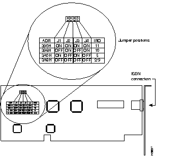
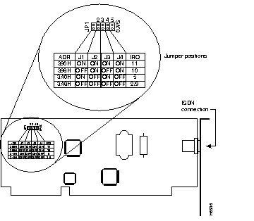
Jumper switches 1 through 4 are located at J1 through J4 and are clearly marked on the ISDN Adapter, as shown in Figure 1-1 (Cisco 201) and Figure 1-2 (Cisco 202). Set these jumpers as necessary to have IRQ and I/O port address settings for the ISDN Adapter that are unique within your PC.
Before you install the ISDN Adapter in your PC, you must configure it with appropriate IRQ and I/O settings. Use the information obtained in the section "Interrupt and I/O Address Information" earlier in this chapter.
In most cases, you should use the following default settings:
If you have other devices in this PC that conflict with the default I/O port address and interrupt, either change the settings for the other device or change the jumpers on your ISDN Adapter. If you change the jumpers on the ISDN Adapter, use Table 1-1 and Table 1-2 to select an alternative I/O port address and interrupt. Note the required jumper settings for your selections.
Because any device that uses electricity must be handled carefully, follow these guidelines to ensure general safety:
Follow these guidelines to ensure safety when you install the ISDN Adapter into your PC chassis:
Warning 
Before working on equipment that is connected to power lines, remove jewelry (including rings, necklaces, and watches). Metal objects will heat up when connected to power and ground and can cause serious burns or weld the metal object to the terminals. (To see translated versions of this warning, refer to the chapter "Translated Safety Warnings.")
Electrostatic discharge (ESD) can damage equipment and impair electrical circuitry. It occurs when electronic components are improperly handled and can result in complete or intermittent failures.
Warning 
This equipment is intended to be grounded. Ensure that the host PC is connected to earth ground during normal use. (To see translated versions of this warning, refer to the chapter "Translated Safety Warnings.")
Always follow ESD-prevention procedures when removing and replacing the ISDN Adapter. Ensure that the PC chassis is electrically connected to earth ground. Wear an ESD-preventive wrist strap, ensuring that it makes good skin contact. Connect the clip to an unpainted surface of the chassis frame to safely channel unwanted ESD voltages to ground. To properly guard against ESD damage and shocks, the wrist strap and cord must operate effectively. If no wrist strap is available, ground yourself by touching the metal part of the chassis.
 | Caution For safety, periodically check the resistance value of the antistatic strap, which should be between 1 and 10 megohms. |
Check the power to ensure that you are receiving "clean" power (free of spike and noise). Install a power conditioner if necessary.
Warning 
Do not touch the power supply when the power cord is connected. For systems with a power switch, line voltages are present within the power supply even when the power switch is off and the power cord is connected. For systems without a power switch, line voltages are present within the power supply when the power cord is connected. (To see translated versions of this warning, refer to the chapter "Translated Safety Warnings.")
Warning 
This product relies on the building's installation for short-circuit (overcurrent) protection. Ensure that a fuse or circuit breaker no larger than 120 VAC, 15A U.S. (240 VAC, 10A international) is used on the phase conductors (all current-carrying conductors). (To see translated versions of this warning, refer to the chapter "Translated Safety Warnings.")
Warning 
Do not work on the system or connect or disconnect cables during periods of lightning activity. (To see translated versions of this warning, refer to the chapter "Translated Safety Warnings.")
Warning 
Before working on a system that has an on/off switch, turn OFF the power and unplug the power cord. (To see translated versions of this warning, refer to the chapter "Translated Safety Warnings.")
This section describes the procedure for installing the ISDN Adapter in a PC.
Warning 
This card is approved only for installation in a PC and with attachments that are either type approved for such apparatus or covered by a general approval. (To see translated versions of this warning, refer to the chapter "Translated Safety Warnings.")
To install the ISDN Adapter, perform the following steps:
Step 1 Turn OFF the computer in which you will install the ISDN Adapter.
Step 2 Unplug the PC's power cable from the wall outlet.
Step 3 Open the cover of the PC according to the instructions in the PC manufacturer's documentation.
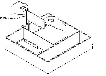
Step 4 Using standard grounding procedures, insert the ISDN Adapter into any free 16-bit slot. This is a half-size board and should fit easily into most chassis. Make sure the adapter's ISDN connector is oriented toward the back of the computer. See Figure 1-3.
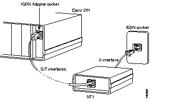
Step 5 If you are using the Cisco 201, you might need to use an NT1 device. Check with your ISDN provider. If your system requires an NT1, use the cable supplied with the Cisco 201 to connect your ISDN Adapter to the S/T interface on the NT1. Then connect the NT1 to the ISDN socket according to the NT1 documentation. See Figure 1-4.
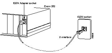
If you are using the Cisco 202 and your ISDN provider does not require an NT1 device, connect your ISDN Adapter to the ISDN socket with the supplied U interface cable. See Figure 1-5.
Step 6 Replace the cover on the PC.
Step 7 Plug the PC's power cable back into the wall outlet.
Step 8 Turn ON the PC.
Your Cisco 200 ISDN Adapter is now installed in your PC. You can now install the Cisco 200 software. For more information, refer to the Cisco 200 for Windows 95 Software Installation Guide and the Cisco 200 for Windows 95 Software Installation quick reference card.
|
|