 |  |
Chapter 4. Path Characteristics
In the last chapter, we attempted to answer a fundamental question, "Do we have a working network connection?" We used tools such as ping to verify basic connectivity. But simple connectivity is not enough for many purposes. For example, an ISP can provide connectivity but not meet your needs or expectations. If your ISP is not providing the level of service you think it should, you will need something to base your complaints on. Or, if the performance of your local network isn't adequate, you will want to determine where the bottlenecks are located before you start implementing expensive upgrades. In this chapter, we will try to answer the question, "Is our connection performing reasonably?"We will begin by looking at ways to determine which links or individual connections compose a path. This discussion focuses on the tool traceroute. Next, we will turn to several tools that allow us to identify those links along a path that might cause problems. Once we have identified individual links of interest, we will examine some simple ways to further characterize the performance of those links, including estimating the bandwidth of a connection and measuring the available throughput.
4.1. Path Discovery with traceroute
This section describes traceroute, a tool used to discover the links along a path. While this is the first step in investigating a path's behavior and performance, it is useful for other tasks as well. In the previous discussion of ping, it was suggested that you work your way, hop by hop, toward a device you can't reach to discover the point of failure. This assumes that you know the path.Path discovery is also an essential step in diagnosing routing problems. While you may fully understand the structure of your network and know what path you want your packets to take through your network, knowing the path your packets actually take is essential information and may come as a surprise.
Once packets leave your network, you have almost no control over the path they actually take to their destination. You may know very little about the structure of adjacent networks. Path discovery can provide a way to discover who their ISP is, how your ISP is connected to the world, and other information such as peering arrangements. traceroute is the tool of choice for collecting this kind of information.
The traceroute program was written by Van Jacobson and others. It is based on a clever use of the Time-To-Live (TTL) field in the IP packet's header. The TTL field, described briefly in the last chapter, is used to limit the life of a packet. When a router fails or is misconfigured, a routing loop or circular path may result. The TTL field prevents packets from remaining on a network indefinitely should such a routing loop occur. A packet's TTL field is decremented each time the packet crosses a router on its way through a network. When its value reaches 0, the packet is discarded rather than forwarded. When discarded, an ICMP TIME_EXCEEDED message is sent back to the packet's source to inform the source that the packet was discarded. By manipulating the TTL field of the original packet, the program traceroute uses information from these ICMP messages to discover paths through a network.
traceroute sends a series of UDP packets with the destination address of the device you want a path to.[16] By default, traceroute sends sets of three packets to discover each hop. traceroute sets the TTL field in the first three packets to a value of 1 so that they are discarded by the first router on the path. When the ICMP TIME_EXCEEDED messages are returned by that router, traceroute records the source IP address of these ICMP messages. This is the IP address of the first hop on the route to the destination.
[16]tracert, a Windows variant of traceroute, uses ICMP rather than UDP. tracert is discussed later in this chapter.Next, three packets are sent with their TTL field set to 2. These will be discarded by the second router on the path. The ICMP messages returned by this router reveal the IP address of the second router on the path. The program proceeds in this manner until a set of packets finally has a TTL value large enough so that the packets reach their destination.
Typically, when the probe packets finally have an adequate TTL and reach their destination, they will be discarded and an ICMP PORT_UNREACHABLE message will be returned. This happens because traceroute sends all its probe packets with what should be invalid port numbers, i.e., port numbers that aren't usually used. To do this, traceroute starts with a very large port number, typically 33434, and increments this value with each subsequent packet. Thus, each of the three packets in a set will have three different unlikely port numbers. The receipt of ICMP PORT_UNREACHABLE messages is the signal that the end of the path has been reached. Here is a simple example of using traceroute:
The results should be fairly self-explanatory. This particular path was 16 hops long. Reverse name lookup is attempted for the IP address of each device, and, if successful, these names are reported in addition to IP addresses. Times are reported for each of the three probes sent. They are interpreted in the same way as times with ping. (However, if you just want times for one hop, ping is generally a better choice.)bsd1# traceroute 205.160.97.122 traceroute to 205.160.97.122 (205.160.97.122), 30 hops max, 40 byte packets 1 205.153.61.1 (205.153.61.1) 1.162 ms 1.068 ms 1.025 ms 2 cisco (205.153.60.2) 4.249 ms 4.275 ms 4.256 ms 3 165.166.36.17 (165.166.36.17) 4.433 ms 4.521 ms 4.450 ms 4 e0.r01.ia-gnwd.Infoave.Net (165.166.36.33) 5.178 ms 5.173 ms 5.140 ms 5 165.166.125.165 (165.166.125.165) 13.171 ms 13.277 ms 13.352 ms 6 165.166.125.106 (165.166.125.106) 18.395 ms 18.238 ms 18.210 ms 7 atm12-0-10-mp.r01.ia-clma.infoave.net (165.166.126.3) 18.816 ms 18.934 ms 18.893 ms 8 Serial5-1-1.GW1.RDU1.ALTER.NET (157.130.35.69) 26.658 ms 26.484 ms 26.855 ms 9 Fddi12-0-0.GW2.RDU1.ALTER.NET (137.39.40.231) 26.692 ms 26.697 ms 26.490 ms 10 smatnet-gw2.customer.ALTER.NET (157.130.36.94) 27.736 ms 28.101 ms 27.738 ms 11 rcmt1-S10-1-1.sprintsvc.net (205.244.203.50) 33.539 ms 33.219 ms 32.446 m s 12 rcmt3-FE0-0.sprintsvc.net (205.244.112.22) 32.641 ms 32.724 ms 32.898 ms 13 gwd1-S3-7.sprintsvc.net (205.244.203.13) 46.026 ms 50.724 ms 45.960 ms 14 gateway.ais-gwd.com (205.160.96.102) 47.828 ms 50.912 ms 47.823 ms 15 pm3-02.ais-gwd.com (205.160.97.41) 63.786 ms 48.432 ms 48.113 ms 16 user58.ais-gwd.com (205.160.97.122) 200.910 ms 184.587 ms 202.771 ms
Although no packets were lost in this example, should a packet be lost, an asterisk is printed in the place of the missing time. In some cases, all three times may be replaced with asterisks. This can happen for several reasons. First, the router at this hop may not return ICMP TIME_EXCEEDED messages. Second, some older routers may incorrectly forward packets even though the TTL is 0. A third possibility is that ICMP messages may be given low priority and may not be returned in a timely manner. Finally, beyond some point of the path, ICMP packets may be blocked.
Other routing problems may exist as well. In some instances traceroute will append additional messages to the end of lines in the form of an exclamation point and a letter. !H, !N, and !P indicate, respectively, that the host, network, or protocol is unreachable. !F indicates that fragmentation is needed. !S indicates a source route failure.
4.1.1. Options
Two options control how much information is printed. Name resolution can be disabled with the -n option. This can be useful if name resolution fails for some reason or if you just don't want to wait on it. The -v option is the verbose flag. With this flag set, the source and packet sizes of the probes will be reported for each packet. If other ICMP messages are received, they will also be reported, so this can be an important option when troubleshooting.Several options may be used to alter the behavior of traceroute, but most are rarely needed. An example is the -m option. The TTL field is an 8-bit number allowing a maximum of 255 hops. Most implementations of traceroute default to trying only 30 hops before halting. The -m option can be used to change the maximum number of hops tested to any value up to 255.
As noted earlier, traceroute usually receives a PORT_UNREACHABLE message when it reaches its final destination because it uses a series of unusually large port numbers as the destination ports. Should the number actually match a port that has a running service, the PORT_UNREACHABLE message will not be returned. This is rarely a problem since three packets are sent with different port numbers, but, if it is, the -p option lets you specify a different starting port so these ports can be avoided.
Normally, traceroute sends three probe packets for each TTL value with a timeout of three seconds for replies. The default number of packets per set can be changed with the -q option. The default timeout can be changed with the -w option.
Additional options support how packets are routed. See the manpage for details on these if needed.
4.1.2. Complications with traceroute
The information traceroute supplies has its limitations. In some situations, the results returned by traceroute have a very short shelf life. This is particularly true for long paths crossing several networks and ISPs.You should also recall that a router, by definition, is a computer with multiple network interfaces, each with a different IP address. This raises an obvious question: which IP address should be returned for a router? For traceroute, the answer is dictated by the mechanism it uses to discover the route. It can report only the address of the interface receiving the packet. This means a quite different path will be reported if traceroute is run in the reverse direction.
Here is the output when the previous example is run again from what was originally the destination to what was originally the source, i.e., with the source and destination exchanged:
There are several obvious differences. First, the format is slightly different because this example was run using Microsoft's implementation of traceroute, tracert. This, however, should present no difficulty.C:\>tracert 205.153.61.178 Tracing route to 205.153.61.178 over a maximum of 30 hops 1 132 ms 129 ms 129 ms pm3-02.ais-gwd.com [205.160.97.41] 2 137 ms 130 ms 129 ms sprint-cisco-01.ais-gwd.com [205.160.97.1] 3 136 ms 129 ms 139 ms 205.160.96.101 4 145 ms 150 ms 140 ms rcmt3-S4-5.sprintsvc.net [205.244.203.53] 5 155 ms 149 ms 149 ms sl-gw2-rly-5-0-0.sprintlink.net [144.232.184.85] 6 165 ms 149 ms 149 ms sl-bb11-rly-2-1.sprintlink.net [144.232.0.77] 7 465 ms 449 ms 399 ms sl-gw11-dc-8-0-0.sprintlink.net [144.232.7.198] 8 155 ms 159 ms 159 ms sl-infonet-2-0-0-T3.sprintlink.net [144.228.220.6] 9 164 ms 159 ms 159 ms atm4-0-10-mp.r01.ia-gnvl.infoave.net [165.166.126.4] 10 164 ms 169 ms 169 ms atm4-0-30.r1.scgnvl.infoave.net [165.166.125.105] 11 175 ms 179 ms 179 ms 165.166.125.166 12 184 ms 189 ms 195 ms e0.r02.ia-gnwd.Infoave.Net [165.166.36.34] 13 190 ms 179 ms 180 ms 165.166.36.18 14 185 ms 179 ms 179 ms 205.153.60.1 15 174 ms 179 ms 179 ms 205.153.61.178 Trace complete.
A closer examination shows that there are more fundamental differences. The second trace is not simply the first trace in reverse order. The IP addresses are not the same, and the number of hops is different.
There are two things going on here. First, as previously mentioned, traceroute reports the IP number of the interface where the packet arrives. The reverse path will use different interfaces on each router, so different IP addresses will be reported. While this can be a bit confusing at first glance, it can be useful. By running traceroute at each end of a connection, a much more complete picture of the connection can be created.
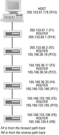
Figure 4-1 shows the first six hops on the path starting from the source for the first trace as reconstructed from the pair of traces. We know the packet originates at 205.153.61.178. The first trace shows us the first hop is 205.153.61.1. It leaves this router on interface 205.153.60.1 for 205.153.60.2. The second of these addresses is just the next hop in the first trace. The first address comes from the second trace. It is the last hop before the destination. It is also reasonable in that we have two addresses that are part of the same class C network. With IP networks, the ends of a link are part of the link and must have IP numbers consistent with a single network.

Figure 4-1. First six hops on path
From the first trace, we know packets go from the 205.153.60.2 to 165.166.36.17. From the reverse trace, we are able to deduce that the other end of the 165.166.36.17 link is 165.166.36.18. Or, equivalently, the outbound interface for the 205.153.60.2 router has the address 165.166.36.18.In the same manner, the next router's inbound interface is 165.166.36.17, and its outbound interface is 165.166.36.34. This can be a little confusing since it appears that these last three addresses should be on the same network. On closer examination of this link and adjacent links, it appears that this class B address is using a subnet mask of /20. With this assumption, the addresses are consistent.
We can proceed in much the same manner to discover the next few links. However, when we get to the seventh entry in the first trace (or to the eighth entry working backward in the second trace), the process breaks down. The reason is simple -- we have asymmetric paths across the Internet. This also accounts for the difference in the number of hops between the two traces.
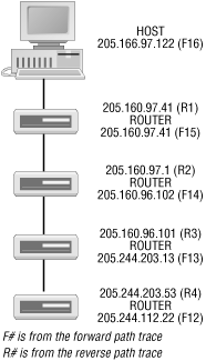
In much the same way we mapped the near end of the path, the remote end can be reconstructed as well. The paths become asymmetric at the seventh router when working in this direction. Figure 4-2 shows the first four hops. We could probably fill in the remaining addresses for each direction by running traceroute to the specific machine where the route breaks down, but this probably isn't worth the effort.

Figure 4-2. First four hops on reverse path
One possible surprise in Figure 4-2 is that we have the same IP number, 205.160.97.41, on each interface at the first hop. The explanation is that dial-in access is being used. The IP number 205.166.97.122 is assigned to the host when the connection is made. 205.160.97.41 must be the access router. This numbering scheme is normal for an access router.Although we haven't constructed a complete picture of the path(s) between these two computers, we have laid out the basic connection to our network through our ISP. This is worth working out well in advance of any problems. When you suspect problems, you can easily ping these intermediate routers to pinpoint the exact location of a problem. This will tell you whether it is your problem or your ISP's problem. This can also be nice information to have when you call your ISP.
To construct the bidirectional path using the technique just described, you need access to a second, remote computer on the Internet from which you can run traceroute. Fortunately, this is not a problem. There are a number of sites on the Internet, which, as a service to the network community, will run traceroute for you. Often called looking glasses, such sites can provide a number of other services as well. For example, you may be able to test how accessible your local DNS setup is by observing how well traceroute works. A list of such sites can be found at http://www.traceroute.org. Alternately, the search string "web traceroute" or "traceroute looking glass" will usually turn up a number of such sites with most search engines.
In theory, there is an alternative way to find this type of information with some implementations of traceroute. Some versions of traceroute support loose source routing, the ability to specify one or more intermediate hops that the packets must go through. This allows a packet to be diverted through a specific router on its way to its destination. (Strict source routing may also be available. This allows the user to specify an exact path through a network. While loose source routing can take any path that includes the specified hops, strict source routing must exactly follow the given path.)
To construct a detailed list of all devices on a path, the approach is to use traceroute to find a path from the source host to itself, specifying a route through a remote device. Packets leave the host with the remote device as their initial destination. When the packets arrive at the remote device, that device replaces the destination address with the source's address, and the packets are redirected back to the source. Thus, you get a picture of the path both coming and going. (Of course, source routing is not limited to just this combination of addresses.)
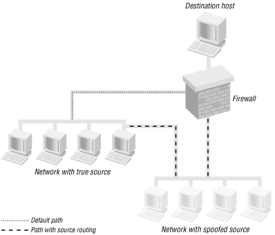
At least, that is how it should work in theory. In practice, many devices no longer support source routing. Unfortunately, source routing has been used in IP spoofing attacks. Packets sent with a spoofed source address can be diverted so they pass through the spoofed device's network. This approach will sometimes slip packets past firewalls since the packet seems to be coming from the right place.
This is shown in Figure 4-3. Without source routing, the packet would come into the firewall on the wrong interface and be discarded. With source routing, the packet arrives on the correct interface and passes through the firewall. Because of problems like this, source routing is frequently disabled.

Figure 4-3. IP source spoofing
One final word of warning regarding traceroute -- buggy or nonstandard implementations exist. Nonstandard isn't necessarily bad; it just means you need to watch for differences. For example, see the discussion of tracert later in this chapter. Buggy implementations, however, can really mislead you.


