3-31
Cisco AVVID Network Infrastructure Enterprise Quality of Service Design
956467
Chapter 3 QoS in an AVVID-Enabled Campus Network
Selecting an Access-Layer Switch
If you are using the Catalyst 4000 with the Layer 3 engine (the WS-X4232), which enables IP, IPX, and
Multicast routing for the switch, you can perform additional uplink configuration. The Layer 3 engine
allows the Catalyst 4000 to support four standard transmit queues with a single threshold on the
two-gigabit uplinks. The four queues are scheduled using a user-configurable WRR algorithm.
Admission to the queues is based on 802.1p CoS value and is user-configurable in pairs.
To enable QoS and change CoS mappings to use the newly created queues, do the following:
Step 1
Enable QoS
cat4k> (enable) set qos enable
Step 2
Map the CoS categories to each of the queues.
cat4k> (enable) set qos map 4q1t 1 1 cos 6-7
cat4k> (enable) set qos map 4q1t 2 1 cos 4-5
cat4k> (enable) set qos map 4q1t 3 1 cos 2-3
cat4k> (enable) set qos map 4q1t 4 1 cos 0-1
Note that the Layer 3 queue numbering is the reverse of the Layer 2 numbering.
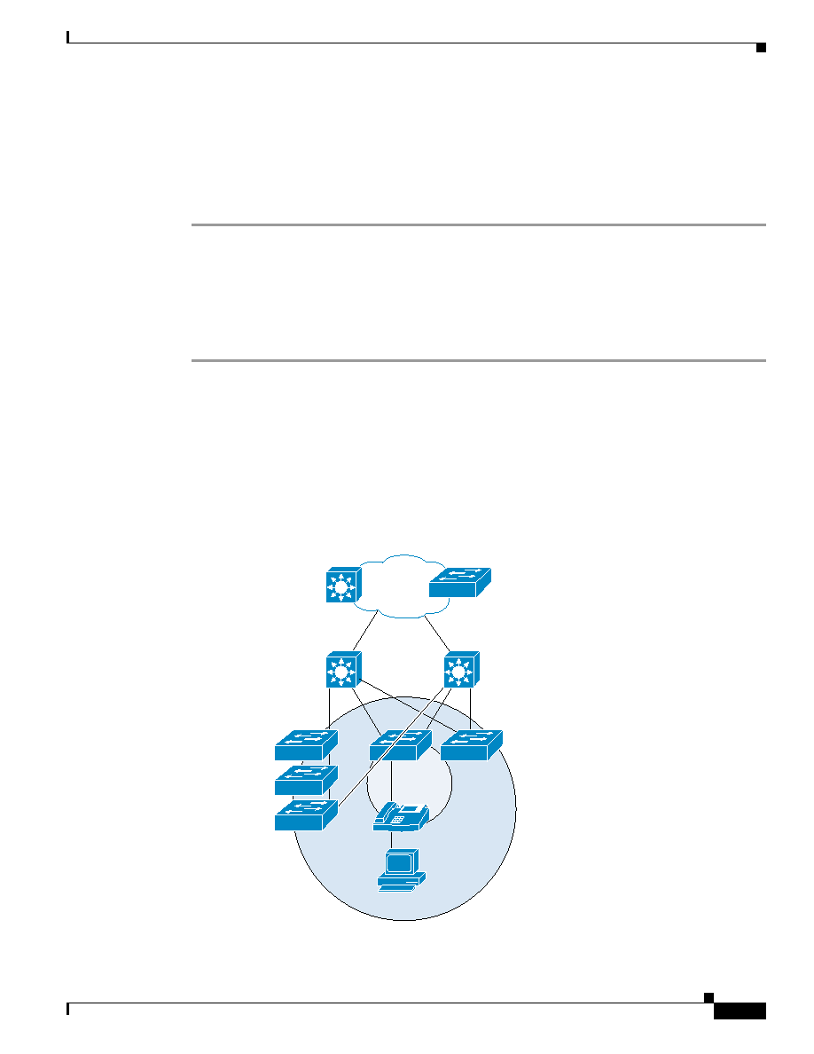
Catalyst 3524-PWR XL as an Access-Layer Switch
shows a general model for the Catalyst 3524-PWR XL as an access device (as illustrated in
the QoS configurations discussed in this chapter).
Figure 3-10 General Model for Catalyst 3524-PWR XL QoS Configurations
Si
Si
IP
VVID=112
VLAN=12
Core
Distribution
Access
Catalyst
6500
Catalyst 3524-PWR
74701
Si