|
|

Table Of Contents
Integrating Cisco Unified CallManager Express with Cisco Unified CallManager
Basic Calls Between Cisco Unified CallManager and Cisco Unified CME
H.323 Call Transfer Using an Empty Capabilities Set
Call Transfer and the Media Termination Point
Connecting Cisco Unified CallManager with Cisco Unified CME
Intersite Call Transfer with Multiple Cisco Unified CME Systems
Connected Party Name and Number Services
Using H.450.x Cisco IP-to-IP Gateway
Integrating Cisco Unified CallManager Express with Cisco Unified CallManager
This chapter covers the deployment of Cisco Unified CallManager Express (Cisco Unified CME) for branch offices in conjunction with a Cisco Unified CallManager deployed at a central office site. In this situation, the central Cisco Unified CallManager site can act as a hub linking the remote Cisco Unified CME sites. Cisco Unified CME and Cisco Unified CallManager can communicate across IP WAN links using H.323 (or using Session Initiation Protocol [SIP] with Cisco Unified CallManager 5.0 or later versions).
In H.323 networks, Cisco Unified CME provides supplementary service interworking (H.450) using Voice over IP (VoIP) hairpin call routing when needed for intersite call transfer and forwarding. This chapter discusses these services in a network that has both Cisco Unified CME systems and one or more Cisco Unified CallManager systems.
The following sections address considerations in designing effective integration and interoperability solutions for Cisco Unified CME and Cisco Unified CallManager.
•
Basic Calls Between Cisco Unified CallManager and Cisco Unified CME
•
•
Note
Goals of Interoperability
Real enterprise VoIP networks that have been designed consistently from the ground up and that adhere to a single uniform architectural approach are rare. The technologies available to network designers have evolved rapidly over the past decade or two. This rapid evolution will probably continue for some time. It requires organizations to continually rethink their network architectures to take advantage of the latest available enhancements. Not only do the technologies change, but so do the companies trying to make best use of them. Companies split and merge and reinvent themselves in a continuous effort to stay profitable and competitive. This leads to real-world networks made up of a mixture of architectures formed by the ad hoc fusion of components contributed by multiple network designs.
Looking at VoIP networks that incorporate Cisco components, you commonly see both central-site Cisco Unified CallManager networks using Cisco Survivable Remote Site Telephony (Cisco SRST) at some remote branch offices coupled with Cisco Unified CME systems used at other remote offices. Being able to interconnect these systems is a fairly important consideration. In fact, some businesses deliberately design their networks using both central and distributed models to take into account issues with geographic variation in the availability of WAN services. For example, in the banking industry, central Cisco Unified CallManager designs have been widely used in city branches located in metropolitan areas where adequate bandwidth and quality of service (QoS)-enabled WAN links are fairly readily available. However, Cisco Unified CME systems have been used in small-town bank branches located in more rural areas where WAN services might be less sophisticated and unable to support voice.
Both Cisco Unified CallManager and Cisco Unified CME support H.323, which you can use to create Cisco Unified CallManager-to-Cisco Unified CME links. Cisco Unified CME also supports SIP for VoIP interconnect. SIP is also being introduced as a WAN trunking interface on Cisco Unified CallManager. This chapter focuses only on the H.323 interconnect option, because the SIP interconnect option is still a work in progress as SIP support on successive Cisco Unified CallManager versions evolves. However, you can expect that most of the architectural issues raised in this chapter are also applicable in the SIP context.
The descriptions contained in this chapter apply to the Cisco Unified CME 3.1 and 3.2 releases and the Cisco Unified CallManager 3.3(3) and 4.0. Newer versions may have different behaviors and options than those described here.
Basic Calls Between Cisco Unified CallManager and Cisco Unified CME
Even before the introduction of Cisco Unified CME, Cisco Unified CallManager used Cisco IOS voice routers to provide a Public Switched Telephone Network (PSTN) access gateway for Cisco Unified CallManager IP phones. Both the H.323 and Media Gateway Control Protocol (MGCP) VoIP protocols can support this function. The choice between these two is partly a historic issue and partly related to the type of PSTN interface used, but this topic is outside the scope of this guide.
Direct MGCP integration between Cisco Unified CME IP phones and Cisco Unified CallManager is not supported. Although this does not preclude the concurrent operation of MGCP (used for the PSTN gateway ports) and H.323-with-Cisco Unified CME on the same Cisco IOS voice router, we do not recommend this configuration. Using MGCP with Cisco Unified CallManager to control the PSTN voice ports on a Cisco Unified CME system would force PSTN traffic originated by the Cisco Unified CME IP phones to route through the Cisco Unified CallManager to reach the PSTN. In most cases, this would be inefficient because it would result in the Cisco Unified CME-to-PSTN voice traffic traversing the Cisco Unified CME-to-Cisco Unified CallManager WAN link twice.
Because Cisco Unified CME is built on top of the Cisco IOS voice infrastructure software foundation also used by the Cisco IOS router-based PSTN gateways, Cisco Unified CME inherits most of the H.323 gateway-to-Cisco Unified CallManager interoperability. You should be aware of some minor differences, however.
In the simple PSTN gateway case, most of the call progress signaling for calls is performed as in-band audio tones. For example, when an IP phone (hosted by Cisco Unified CallManager) places an outbound call to the PSTN, the ringing tone (also called the alerting or ringback tone) heard by the caller is usually generated as an audio signal that is passed through end-to-end from the PSTN trunk. This means that the audio path from the gateway to the IP phone is opened and active before the call is connected.
In the case where a call is placed from a Cisco Unified CallManager IP phone to a Cisco Unified CME IP phone, the ringing tone is provided as an out-of-band H.323 indication from Cisco Unified CME (through H.323 control channel signaling). This means that the Cisco Unified CME system signals to the Cisco Unified CallManager, which in turn instructs the Cisco Unified CallManager IP phone to generate the ringing tone locally.
The reasons for this difference include the following:
•
•
•
This issue of ringing-tone signaling causes some specific changes in the H.323 protocol exchange that Cisco Unified CME uses when talking to a Cisco Unified CallManager, compared with H.323 signaling to another Cisco IOS PSTN gateway, for example.
To get Cisco Unified CallManager to provide local ringing-tone generation for outbound calls from Cisco Unified CallManager, the Cisco Unified CME delays negotiation of the media path until the call connects. The Cisco Unified CallManager 3.3 and 4.0 H.323 implementations assume that in-band ringing tone is provided (by the Cisco Unified CME or another H.323 device) on all calls that negotiate the media path (using H.245) before the call is connected. This delayed negotiation can lead to a minor delay (typically about a quarter of a second) in establishing the audio path when the call actually connects. This delay is called the voice cut-through delay.
Cisco Unified CME only uses this delayed H.245 media negotiation on calls that go to or from a Cisco Unified CallManager. Cisco Unified CME (3.1 and later versions) can explicitly identify Cisco Unified CallManager calls based on special nonstandard H.323 information element (IE) messages that Cisco Unified CallManager attaches to its H.323 call setup, proceeding, alerting, and connected messages. See Figure 7-1.
Figure 7-1 Cisco Unified CallManager-to-Cisco Unified CME 3.1 Basic Call
Call Transfer
Cisco Unified CallManager and Cisco Unified CME implement significantly different approaches to handling call transfer. These differences are related to the basic architectural differences that exist between a highly centralized (Cisco Unified CallManager) and fully distributed (Cisco Unified CME) VoIP network architecture.
In Cisco Unified CME (and all other Cisco IOS software-based voice gateways), the preferred mechanism for handling call transfer is H.450.2. This allows calls to be transferred in a highly optimized way not only between phones on the same Cisco Unified CME system, but also between different Cisco Unified CME systems. This is a significant attribute when you consider that Cisco Unified CME system-based VoIP networks can include hundreds or thousands of individual Unified CME nodes. Each Cisco Unified CME node is a distinct and separate H.323 device with autonomous call processing.
In Cisco Unified CallManager, the call transfer mechanism is designed to allow calls to be transferred between hundreds or thousands of IP phones controlled by the same Cisco Unified CallManager (or Cisco Unified CallManager cluster). Furthermore, in a Cisco Unified CallManager environment, there is a significant need to separate the H.323 control path from the H.323 media path. Because a single Cisco Unified CallManager server can be required to control approximately 2500 IP phones, it's impossible for the server to play an active intermediary role in the media path for all phone calls. Consider that there is a media packet in each direction every 20 milliseconds (ms) for each call, and then multiply this by 2500 phones. To allow a Cisco Unified CallManager to support this number of phones, the media path for phone-to-phone calls must be directly between the phones whenever possible.
Note
One other issue to examine when comparing Cisco Unified CallManager to Cisco Unified CME operation is that for enterprise telephone systems, the ratio between internal and external call counts is related to the overall size of the phone system. As the number of extensions attached to a phone system increases, so does the relative proportion of internal calls compared to external calls. For example, in a system with only ten phones, almost 100 percent of phone calls are external calls between a phone and the outside world. In a system with 1000 phones, the external calls may make up only about 10% of the total call volume.
You can view this call transfer difference between Cisco Unified CallManager and Cisco Unified CME as being equivalent to the difference between an internal intraprivate branch exchange (PBX) call transfer and an inter-PBX transfer. Viewed from the legacy PBX perspective, you can see that these are fundamentally different problems.
The following sections describe integration-related call transferring considerations:
•
•
•
•
•
H.323 Call Transfer Using an Empty Capabilities Set
The problem with call transfer becomes more complex when you consider the interaction of Cisco Unified CallManager IP phones with an external H.323 network. When an H.323 call exists between an external H.323 device and a Cisco Unified CallManager IP phone, the preferred arrangement is to have a direct media path between the endpoints that does not pass through the Cisco Unified CallManager server. In some cases, a direct media path is not possible (as described in the "Call Transfer and the Media Termination Point" section. In this case, it is necessary to introduce a Media Termination Point (MTP) into the media path. The MTP acts as a media relay or middleman and relays the Real-Time Transport Protocol (RTP) voice packets between the two terminating endpoints. The call signaling path does pass through the Cisco Unified CallManager server. The H.323 signaling is terminated on the Cisco Unified CallManager server and then is converted into SCCP to talk to the IP phone. The Cisco Unified CallManager is required to participate in this signaling path to provide the needed conversion between H.323 and SCCP.
When there is a call transfer for an H.323 call from one Cisco Unified CallManager IP phone (phone A) to another (phone B), the H.323 signaling path does not change. It remains terminated on the Cisco Unified CallManager server. The Cisco Unified CallManager server establishes a new SCCP signaling path to phone B. Of course, the media path also has to change. Changing the media path on the IP phones is easy. The Cisco Unified CallManager simply sends the appropriate SCCP messages to phone B, telling it to participate in the media connection to the external H.323 endpoint.
To change the media connection on the H.323 side, the Cisco Unified CallManager uses a mechanism known as Empty Capabilities Set (ECS). This mechanism informs the external H.323 device that it should stop sending its media packets to phone A's IP address and should instead send the media packets to phone B's IP address. This mechanism allows the media stream to be redirected to the transfer-to destination phone while preserving the original H.323 control path connection. Figure 7-2 shows the media path before and after the transfer.
Figure 7-2 Cisco Unified CallManager ECS Transfer
With this arrangement, there is no limit on the number of times the call can be transferred, as long as the call termination point remains within the set of phones controlled by Cisco Unified CallManager. This is the behavior you would expect, considering how a legacy time-division multiplexing (TDM)-based PBX works. There is usually no limit on the number of internal chained transfers. Cisco Unified CME (and Cisco IOS software-based H.323 PSTN gateways in general) supports receipt of ECS signaling from Cisco Unified CallManager but does not initiate ECS signaling for call transfer.
H.323-to-H.323 Call Transfer
Now consider what happens when the transfer-to destination is not an internal IP phone. In the case of an H.323 endpoint that calls an internal IP phone and then is transferred to a second external H.323 endpoint, the same ECS mechanism can be used. The transferred call has its H.323 signaling path relayed through the Cisco Unified CallManager, but the media path is direct between the two external H.323 endpoints.
This process works fine except in the case where one of the H.323 endpoints wants to further transfer the call (or perform some other media-related operation, such as call hold with music on hold [MOH]). In general, chained H.323 ECS operations do not work well. This is because the attempt to chain-transfer the call results in a very indirect H.323 control path. None of the entities in the H.323 control path is directly connected to both of the call media final termination points. This means that the media path negotiations have to pass through two transit points instead of one.
For example, for the first transfer, A calls B and is transferred to C. The transferor node B is in direct contact with both the A and C points and can help them negotiate a mutually acceptable media path. The H.323 control path is A-to-B-to-C, but the media path is A-to-C.
A problem arises when C wants to transfer the call to D. This would create an A-to-B-to-C-to-D H.323 control path. In this case, neither of the B or C middlemen is in direct contact with both of the A and D final endpoints. This can make successful media negotiation between A and D quite difficult to achieve in practice.
Call Transfer and the Media Termination Point
One way to solve the problem of end-to-end negotiation of the media path is to use an MTP that can provide transcoding services. One example of this type of MTP is the digital signal processor (DSP) farms that are supported on Cisco IOS voice-enabled routers. DSP farms are controlled by a Cisco Unified CallManager (or Cisco Unified CME) using SCCP. The term transcode means the ability to convert the media stream from one codec type to another. You may sometimes see this term abbreviated as xcode.
If you introduce a transcoding MTP into the media path, there is no need to perform end-to-end media path renegotiation for the chained call transfer case. The use of an MTP simplifies the problem of connecting or transferring a call through multiple H.323 endpoints, because it removes the need to perform a multiparty negotiation and capabilities adaptation between all the H.323 entities involved. Figure 7-3 shows the media path before and after the transfer.
Figure 7-3 Cisco Unified CallManager Transfer with MTP
In general, the MTP approach simplifies the set of H.323 signaling operations required and increases the overall the ability to interoperate. This is true even in cases where everyone uses the same codec type and actual transcoding of codecs is unnecessary.
The drawback to this approach is the impact on overall scalability, because an MTP channel is needed for every H.323 (external) call. A mitigating factor in this situation (see the "Call Transfer" section) is that as the number of IP phones in the Cisco Unified CallManager cluster increases, the fraction of H.323 calls to internal calls decreases. In general, the expense of adding MTPs is worthwhile because of the reduction in H.323 interoperability issues.
Another issue with the chained transfer cases is that each leg in the transfer chain contributes additional delay to both the signaling and media path. If a call is chain-transferred too many times, the resulting delay and voice quality will probably become unacceptable. In general, end-to-end one-way delays of more than 150 to 200 ms are unacceptable to phone users.
The chained-transfer issues apply only to intersite transfers that are chained across multiple separate H.323 nodes. Transfers within the internal scope of a single H.323 node do not suffer from this problem, because (with an MTP) the transfer is invisible to the other H.323 endpoints involved.
Connecting Cisco Unified CallManager with Cisco Unified CME
This section examines how what you've learned so far in this chapter relates to connecting a Cisco Unified CallManager to a network of Cisco Unified CME systems.
You learned in "Connecting Multiple Cisco Unified CallManager Express Systems with VoIP," that Cisco Unified CME prefers to perform call transfers using H.450.2 but can perform VoIP-to-VoIP hairpin or Cisco IP-to-IP Gateway routing when needed. You also learned that a Cisco Unified CME can automatically detect calls to or from a Cisco Unified CallManager and can use this information to disable its normal H.450.2 behavior. The final piece of this puzzle is to understand that an H.323 call to a Cisco Unified CME IP phone always passes through an MTP-like mechanism within Cisco Unified CME. This arrangement allows the Cisco Unified CME to optionally perform its internal transfers without using H.450.2 and without affecting the H.323 connection to Cisco Unified CallManager.
In Cisco Unified CME, the MTP is the Cisco Unified CME router itself. However, you still need a separate MTP device on the Cisco Unified CallManager side in case the Cisco Unified CallManager phone itself invokes additional call transfer operations on the same call. Figure 7-4 shows Cisco Unified CME connecting to a Cisco Unified CallManager using MTP.
Figure 7-4 Cisco Unified CallManager and Cisco Unified CME Connected Using MTPs
The issue of MTP scalability largely does not apply to Cisco Unified CME for two reasons. First, the RTP media stream voice packets have to pass through the Cisco Unified CME router anyway. Even if Cisco Unified CME did not deliberately invoke MTP treatment for the media stream packets, the packets would still need to be routed by the Cisco Unified CME IP routing function. In many cases, the router might also have to perform other operations on the media stream packets, such as firewall and Network Address Translation (NAT). As a result, no additional real-world penalty is incurred by the MTP treatment; it is more or less free.
Second, the number of IP phones that Cisco Unified CME supports is relatively low compared to a Cisco Unified CallManager. The number of phones supported by a Cisco Unified CME router is scaled according to the overall performance of the specific Cisco IOS router model used. Many different router models are available with IP phone support, which ranges from 24 phones to about 240 phones.
The only condition under which the Cisco Unified CME MTP treatment incurs an additional cost is when you actually need codec transcoding. Even in this case, the additional cost usually is not large, because you almost certainly already have DSP resources included in your Cisco Unified CME router to support its PSTN ports. In many cases, you can meet the MTP transcoding requirement simply by adding DSP chips to your existing voice-port hardware. This is in contrast to the need to explicitly add an entire voice module solely for DSP farm transcoding purposes.
However, in many cases transcoding for call transfer is unneeded, because a Cisco Unified CME has only a single WAN link carrying H.323 calls, and all the H.323 calls tend to use the same codec (either G.711 or G.729). Your Cisco Unified CME may still need DSP farm transcoding services to support three-party conferencing for G.729 calls (see "Connecting Multiple Cisco Unified CallManager Express Systems with VoIP").
Note
Intersite Call Transfer with Multiple Cisco Unified CME Systems
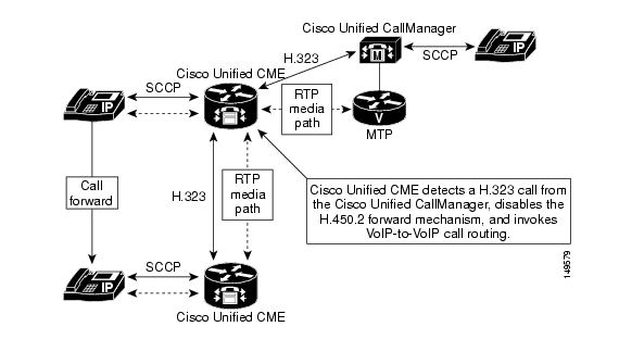
The final call transfer scenario you should understand is what happens with a call placed from a Cisco Unified CallManager to a Cisco Unified CME system that is then transferred to a second Cisco Unified CME system (see Figure 7-5). In this case, the first Cisco Unified CME detects that the call is from a Cisco Unified CallManager. As a result, it invokes VoIP-to-VoIP Cisco IP-to-IP Gateway or hairpin routing to provide the call path (see "Connecting Multiple Cisco Unified CallManager Express Systems with VoIP," for details).
Figure 7-5 Intersite Call Transfer for a Cisco Unified CallManager with Multiple Cisco Unified CME Systems
Call Forwarding
Call forwarding (for busy, no-answer, and unconditional forwarding) raises many of the same issues as call transfer. Likewise, these issues can be addressed using an MTP to simplify the H.323 signaling operations.
The preferred method of handling call forwarding for Cisco Unified CME is H.450.3. Again, Cisco Unified CME can disable its H.450.3 feature when it detects calls from a Cisco Unified CallManager. Under these circumstances, the Cisco Unified CME system falls back to using internal call forwarding or VoIP-to-VoIP call routing for intersite call forwarding.
Note
Just like the call-transfer case, an MTP allows internal call forwarding to occur without impact to the H.323 call leg. Of the three types of forwarding—busy, no-answer, and unconditional—the no-answer form generally involves more signaling complexity. When a call forward no-answer occurs, the preliminary call negotiation for the original called phone must be revoked (after the no-answer timeout). It is replaced with a new call to the forward-to destination phone. The forwarded call can potentially require the use of different parameters than those negotiated for the original called phone. The busy and unconditional forms of call forwarding usually do not involve a preliminary call actually reaching the forwarding phone; this tends to simplify the signaling. Figure 7-6 shows call forwarding between a Cisco Unified CME system and a Cisco Unified CallManager using MTP.
Figure 7-6 Cisco Unified CallManager and Cisco Unified CME Call Forwarding with MTP
You can see that Figure 7-5, which shows call transfer, and Figure 7-6, which shows call forwarding, are nearly identical. Figure 7-7 shows intersite Cisco Unified CME call forwarding for a call from a Cisco Unified CallManager. Compare it to Figure 7-5 for the equivalent call transfer case.
Figure 7-7 Cisco Unified CallManager Forwarding with Multiple Cisco Unified CME Systems
For the special case of call forwarding to a voice mail system, note that the H.323 call setup for the forwarded call includes the original called number (the number of the forwarding phone). This can be used to provide integration with the voice mail system and to allow automatic selection of the voice mailbox that belongs to the forwarding phone.
Note
Figure 7-8 The Problem with Chained Hairpin Calls
Connected Party Name and Number Services
One of the reasons why Cisco Unified CME uses the H.450.2 call transfer and H.450.3 call forwarding mechanisms is that it provides a standard means to support updating of the originating phone's display to track who the connected-to party is. Connected party display is often considered an important feature in business telephone networks. The connected party display is broader than the usual residential caller ID display you may be familiar with at home. Not only does it provide information about the calling party for inbound calls, but it also provides information about the called party for outbound calls. The connected party display can show you the name of the person you have called, for example. This is in contrast to simply displaying the number you dialed. Also, the standard caller ID display function provides a one-time indication of who the caller is only at the beginning of an incoming call. The connected party display feature allows for midcall updates of the connected party information that occur when the far end of the call performs a call transfer.
For example, after a caller has been transferred, the phone display can be updated to show the name and number of the extension he has been transferred to. Likewise, when you receive a call transferred to you by someone else, your phone display may initially show the caller ID of the person who is transferring the call to you. After the transfer is complete, your phone's display may update to show the caller ID of the transferee (caller).
When Cisco Unified CME disables the H.450.2 and H.450.3 mechanisms to interwork with Cisco Unified CallManager, this display update mechanism is unavailable. However, Cisco Unified CallManager has its own mechanism for performing connected party display updates. Cisco Unified CallManager uses H.323 display and information IEs. Cisco Unified CME also supports these IEs for performing connected party display updates.
The H.323 IE messages are carried as part of the H.323 signaling path. They are unaffected by the use of an MTP because they are informational messages only and do not generate changes to the call signaling state. This means that even when a Cisco Unified CallManager performs an internal call transfer hidden behind an MTP, the H.323 information and display IEs are received by the Cisco Unified CME system and are used to provide display updates. Not only can Cisco Unified CME receive display IEs from Cisco Unified CallManager, but it also sends display IEs to Cisco Unified CallManager when Cisco Unified CME performs internal transfer or forwarding.
Cisco Unified CME sends these display IE messages for all H.323 calls regardless of whether a Cisco Unified CallManager is involved in a call. This means that you can still get intersite connected-to party updates in Cisco Unified CME networks where you have chosen to globally disable H.450 services.
Using H.450.x Cisco IP-to-IP Gateway
One final point to understand in planning your Cisco Unified CallManager-to-Cisco Unified CME connections is the advantages that an H.450 Cisco IP-to-IP gateway can provide. You can insert an H.450 Cisco IP-to-IP gateway into the call path between your Cisco Unified CME network and Cisco Unified CallManager, and use it to mitigate some of the issues that arise from the use of VoIP-to-VoIP call paths. If an intersite call transfer or forward initiated by a Cisco Unified CME creates a VoIP hairpin call, you can often use an H.450 Cisco IP-to-IP gateway co-located with your Cisco Unified CallManager to avoid most of the voice path delay caused. Just hairpin the media stream through the Cisco Unified CME system located at the end of a narrow-bandwidth WAN link. See "Connecting Multiple Cisco Unified CallManager Express Systems with VoIP," for more details about IP-to-IP gateways.
![]()
![]()
![]()
![]()
![]()
![]()
![]()
![]()
Posted: Thu Sep 14 16:36:51 PDT 2006
All contents are Copyright © 1992--2006 Cisco Systems, Inc. All rights reserved.
Important Notices and Privacy Statement.