cc/td/doc/product/voice/its/cmeadm
hometocprevnextglossaryfeedbacksearchhelp
PDF

Table Of Contents

Defining Network Parameters

Contents

Prerequisites for Defining Network Parameters

Restrictions for Defining Network Parameters

Information About Defining Network Parameters

DHCP Service

Network Time Protocol for the Cisco Unified CME Router

DTMF Relay

SIP Register Support

Out-of-Dialog REFER

How to Define Network Parameters

Enabling Calls in Your VoIP Network

Defining DHCP

Enabling Network Time Protocol on the Cisco Unified CME Router

Configuring DTMF Relay for H.323 Networks in Multisite Installations

Configuring SIP Trunk Support

Verifying SIP Trunk Support Configuration

Changing the TFTP Address on a DHCP Server

Enabling OOD-R

Verifying OOD-R Configuration

Troubleshooting OOD-R

Configuration Examples for Network Parameters

NTP Server: Example

DTMF Relay for H.323 Networks: Example

OOD-R: Example

Where to Go Next

Additional References

Related Documents

Technical Assistance

Feature Information for Network Parameters


Defining Network Parameters


Last Updated: September 27, 2007

This chapter describes how to define parameters that enable Cisco Unified Communications Manager Express (Cisco Unified CME) to work with your network.


Note If you used Cisco Unified Communications Express - QCT to generate a basic telephony configuration, you can skip this module unless you want to modify the configuration to relay DHCP requests from IP phones to a DHCP server on a different router.


Finding Feature Information in This Module

Your Cisco Unified CME version may not support all of the features documented in this module. For a list of the versions in which each feature is supported, see the "Feature Information for Network Parameters" section.

Contents

Prerequisites for Defining Network Parameters

Information About Defining Network Parameters

How to Define Network Parameters

Configuration Examples for Network Parameters

Where to Go Next

Additional References

Feature Information for Network Parameters

Prerequisites for Defining Network Parameters

IP routing must be enabled.

VoIP networking must be operational. For quality and security purposes, we recommend you have separate virtual LANs (VLANs) for data and voice. The IP network assigned to each VLAN should be large enough to support addresses for all nodes on that VLAN. Cisco Unified CME phones receive their IP addresses from the voice network, whereas all other nodes such as PCs, servers, and printers receive their IP addresses from the data network. For configuration information, see the "How to Configure VLANs on a Cisco Switch" section on page 73.

If applicable, PSTN lines are configured and operational.

If applicable, the WAN links are configured and operational.

Trivial File Transfer Protocol (TFTP) must be enabled on the router to allow IP phones to download phone firmware files.

To support IP phones that are running SIP to be directly connected to the Cisco Unified CME router, Cisco Unified CME 3.4 or later must be installed on the router. For installation information, see "Installing and Upgrading Cisco Unified CME Software" on page 87.

To provide voice-mail support for phones connected to the Cisco Unified CME router, install and configure voice mail on your network.

Restrictions for Defining Network Parameters

In Cisco Unified CME 4.0 and later versions, Layer-3-to-Layer-2 VLAN Class of Service (CoS) priority marking is not automatically processed. Cisco Unified CME 4.0 and later versions will continue to mark Layer 3, but Layer 2 marking is now only handled in the Cisco IOS software. Any Quality of Service (QoS) design that requires Layer 2 marking will have to be explicitly configured, either on a Catalyst switch that supports this capability or on the Cisco Unified CME router under the Ethernet interface configuration. For configuration information, see the Enterprise QoS Solution Reference Network Design Guide.

Information About Defining Network Parameters

To configure network parameters, you should understand the following concepts:

DHCP Service

Network Time Protocol for the Cisco Unified CME Router

DTMF Relay

SIP Register Support

Out-of-Dialog REFER

DHCP Service

When a Cisco Unified IP phone is connected to the Cisco Unified CME system, it automatically queries for a Dynamic Host Configuration Protocol (DHCP) server. The DHCP server responds by assigning an IP address to the Cisco Unified IP phone and providing the IP address of the TFTP server through DHCP option 150. Then the phone registers with the Cisco Unified CME server and attempts to get configuration and phone firmware files from the TFTP server.

For configuration information, perform only one of the following procedures to set up DHCP service for your IP phones:

If your Cisco Unified CME router is the DHCP server and you can use a single shared address pool for all your DHCP clients, see the "Defining a Single DHCP IP Address Pool" section.

If your Cisco Unified CME router is the DHCP server and you need separate pools for non-IP-phone DHCP clients, see the "Defining a Separate DHCP IP Address Pool for Each DHCP Client" section.

If the Cisco Unified CME router is not the DHCP server and you want to relay DHCP requests from IP phones to a DHCP server on a different router, see the "Defining a DHCP Relay" section.

Network Time Protocol for the Cisco Unified CME Router

Network Time Protocol (NTP) allows you to synchronize your Cisco Unified CME router to a single clock on the network, known as the clock master. NTP is disabled on all interfaces by default, but it is essential for Cisco Unified CME so you must ensure that it is enabled. For information about configuring NTP for the Cisco Unified CME router, see the "Enabling Network Time Protocol on the Cisco Unified CME Router" section.

DTMF Relay

IP phones connected to Cisco Unified CME systems require the use of out-of-band DTMF relay to transport DTMF (keypad) digits across VoIP connections. The reason for this is that the codecs used for in-band transport may distort DTMF tones and make them unrecognizable. DTMF relay solves the problem of DTMF tone distortion by transporting DTMF tones out-of-band, or separate, from the encoded voice stream.

For IP phones on H.323 networks, DTMF is relayed using the H.245 alphanumeric method, which is defined by the ITU H.245 standard. This method separates DTMF digits from the voice stream and sends them as ASCII characters in H.245 user input indication messages through the H.245 signaling channel instead of the RTP channel. For information about configuring a DTMF relay in a multisite installation, see the "Configuring DTMF Relay for H.323 Networks in Multisite Installations" section.

To use remote voice-mail or IVR applications on SIP networks from Cisco Unified CME phones, the DTMF digits used by the Cisco Unified CME phones must be converted to the RFC 2833 in-band DTMF relay mechanism used by SIP phones. The SIP DTMF relay method is needed in the following situations:

When SIP is used to connect a Cisco Unified CME system to a remote SIP-based IVR or voice-mail application.

When SIP is used to connect a Cisco Unified CME system to a remote SIP-PSTN voice gateway that goes through the PSTN to a voice-mail or IVR application.

The requirement for out-of-band DTMF relay conversion is limited to SCCP phones. SIP phones natively support in-band DTMF relay as specified in RFC 2833.

To use voice mail on a SIP network that connects to a Cisco Unity Express system, which uses a nonstandard SIP Notify format, the DTMF digits used by the Cisco Unified CME phones must be converted to the Notify format. Additional configuration may be required for backward compatibility with Cisco CME 3.0 and 3.1. For configuration information about enabling DTMF relay for SIP networks, see "Configuring SIP Trunk Support" section.

SIP Register Support

SIP register support enables a SIP gateway to register E.164 numbers with a SIP proxy or SIP registrar, similar to the way that H.323 gateways can register E.164 numbers with a gatekeeper. SIP gateways allow registration of E.164 numbers to a SIP proxy or registrar on behalf of analog telephone voice ports (FXS) and IP phone virtual voice ports (EFXS) for local SCCP phones.

When registering E.164 numbers in dial peers with an external registrar, you can also register them with a secondary SIP proxy or registrar to provide redundancy. The secondary registration can be used if the primary registrar fails. For configuration information, see the "Basic SIP Configuration" chapter in the Cisco IOS SIP Configuration Guide.


Note No commands allow registration between the H.323 and SIP protocols.


By default, SIP gateways do not generate SIP Register messages, so the gateway must be configured to register the gateway's E.164 telephone numbers with an external SIP registrar. For information about configuring the SIP gateway to register phone numbers with Cisco Unified CME, see the "Configuring SIP Trunk Support" section.

Out-of-Dialog REFER

Out-of-dialog REFER (OOD-R) allows remote applications to establish calls by sending a REFER message to Cisco Unified CME without an initial INVITE. After the REFER is sent, the remainder of the call setup is independent of the application and the media stream does not flow through the application. The application using OOD-R triggers a call setup request that specifies the Referee address in the Request-URI and the Refer-Target in the Refer-To header. The SIP messaging used to communicate with Cisco Unified CME is independent of the end-user device protocol which can be SIP, SCCP, H.323, or POTS. Click-to-dial is an example of an application that can be created using OOD-R.

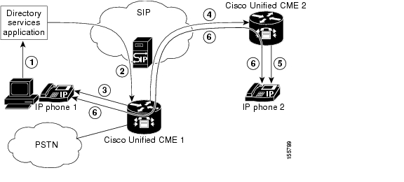
A click-to-dial application allows users to combine multiple steps into one click for a call setup. For example, a user can click a web-based directory application from their PC to look up a telephone number, off-hook their desktop phone, and dial the called number. The application initiates the call setup without the user having to out-dial from their own phone. The directory application sends a REFER message to Cisco Unified CME which sets up the call between both parties based on this REFER.

Figure 6 shows an example of OOD-R being used by a click-to-dial application. In this scenario, the following events occur (refer to the event numbers in the illustration):

1. Remote user clicks to dial.

2. Application sends out-of-dialog REFER to Cisco Unified CME 1.

3. Cisco Unified CME 1 connects to SIP phone 1 (Referee).

4. Cisco Unified CME 1 sends INVITE to Cisco Unified CME 2.

5. Cisco Unified CME 2 sends INVITE to SIP phone 2 (Refer-Target) and the call is accepted.

6. Voice path is created between the two SIP phones.

Figure 6 Click-to-Dial Application using Out-of-Dialog REFER

The initial OOD-R request can be authenticated and authorized using RFC 2617-based digest authentication. To support authentication, Cisco Unified CME retrieves the credential information from a text file stored in flash. This mechanism is used by Cisco Unified CME in addition to phone-based credentials. The same credential file can be shared by other services that require request-based authentication and authorization such as presence service. Up to five credential files can be configured and loaded into the system. The contents of these five files are mutually exclusive, meaning the username and password pairs must be unique across all the files. The username and password pairs must also be different than those configured for SCCP or SIP phones in a Cisco Unified CME system.

For configuration information, see the "Enabling OOD-R" section.

How to Define Network Parameters

This section contains the following tasks. You may not need to perform all of these procedures.

Enabling Calls in Your VoIP Network (required)

Defining DHCP (required)

Enabling Network Time Protocol on the Cisco Unified CME Router (required)

Configuring DTMF Relay for H.323 Networks in Multisite Installations (optional)

Configuring SIP Trunk Support (optional)

Verifying SIP Trunk Support Configuration (optional)

Changing the TFTP Address on a DHCP Server (optional)

Enabling OOD-R (optional)

Verifying OOD-R Configuration (optional)

Troubleshooting OOD-R (optional)

Enabling Calls in Your VoIP Network

To enable calls between endpoints in Cisco Unified CME, perform the following steps.

Restrictions

SIP endpoints are not supported on H.323 trunks. SIP endpoints are supported on SIP trunks only.

Cisco Unified CME 3.4 and later versions support Media Flow-through mode only; enabling SIP-to-SIP calls is required before you can successfully make SIP-to-SIP calls.

SUMMARY STEPS

1. enable

2. configure terminal

3. voice service voip

4. allow-connections from-type to to-type

5. sip

6. registrar server [expires [max sec] [min sec]

7. end

DETAILED STEPS

 
Command or Action
Purpose

Step 1 

enable

Example:

Router> enable

Enables privileged EXEC mode.

Enter your password if prompted.

Step 2 

configure terminal

Example:

Router# configure terminal

Enters global configuration mode.

Step 3 

voice service voip

Example:

Router(config)# voice service voip

Enters voice service configuration mode and specifies Voice over IP (VoIP) encapsulation.

Step 4 

allow-connections from-type to to-type

Example:

Router(config-voi-srv)# allow-connections h323 to h323

Router(config-voi-srv)# allow-connections h323 to SIP

Router(config-voi-srv)# allow-connections SIP to SIP

Enables calls between specific types of endpoints in a VoIP network.

A separate allow-connections command is required for each type of endpoint to be supported.

Step 5 

sip

Example:

Router(config-voi-srv)# sip

(Optional) Enters SIP configuration mode.

Required if you are connecting IP phones running SIP directly in Cisco CME 3.4 and later.

Step 6 

registrar server [expires [max sec][min sec]]

Example:

Router(config-voi-sip)# registrar server expires max 600 min 60

(Optional) Enables SIP registrar functionality in Cisco Unified CME.

Required if you are connecting IP phones running SIP directly in Cisco CME 3.4 and later.

Cisco Unified CME does not maintain a persistent database of registration entries across reloads. If the WAN is down and you reboot your Cisco Unified CME router, when the router reloads it will have no database of SIP phone registrations. The SIP phones will have to register again, which could take several minutes, as SIP phones do not use a keepalive functionality. We recommend that you change the expiry

max sec—(Optional) Range: 600 to 86400. Default: 3600. Recommended value: 600.

min sec—(Optional) Range: 60 to 3600. Default: 60.

Step 7 

exit

Example:

Router(config-voi-sip)# exit

Exits dial-peer configuration mode.

Step 8 

sip-ua

Example:

Router(config)# sip-ua

Enters SIP user-agent configuration mode.

Step 9 

notify telephone-event max-duration time

Example:

Router(config-sip-ua)# notify telephone-event max-duration 2000

Configures the maximum time interval allowed between two consecutive NOTIFY messages for a single DTMF event.

max-duration time—Range: 500 to 3000. Default: 2000.

Step 10 

registrar {dns:host-name | ipv4:ip-address} expires seconds [tcp] [secondary]

Example:

Router(config-sip-ua)# registrar ipv4:10.8.17.40 expires 3600 secondary

Registers E.164 numbers on behalf of analog telephone voice ports (FXS) and IP phone virtual voice ports (EFXS) with an external SIP proxy or SIP registrar server.

Step 11 

retry register number

Example:

Router(config-sip-ua)# retry register 10

Sets the total number of SIP Register messages that the gateway should send.

number—Number of Register message retries. Range: 1 to 10. Default: 10.

Step 12 

timers register time

Example:

Router(config-sip-ua)# timers register 500

Sets how long the SIP user agent (UA) waits before sending Register requests.

time—Waiting time, in milliseconds. Range: 100 to 1000. Default: 500.

Step 13 

end

Example:

Router(config-voi-sip)# end

Exits configuration mode and enters privileged EXEC mode.

Defining DHCP

To set up DHCP service for your DHCP clients, perform only one of the following procedures:

If your Cisco Unified CME router is the DHCP server and you can use a single shared address pool for all your DHCP clients, see Defining a Single DHCP IP Address Pool.

If your Cisco Unified CME router is the DHCP server and you need separate pools for each IP phone and each non-IP-phone DHCP client, see Defining a Separate DHCP IP Address Pool for Each DHCP Client.

If the Cisco Unified CME router is not the DHCP server and you want to relay DHCP requests from IP phones to a DHCP server on a different router, see Defining a DHCP Relay.

Defining a Single DHCP IP Address Pool

To create a shared pool of IP addresses for all DHCP clients, perform the following step.


Note Do not perform this task if you already have a DHCP server on the LAN that can be used to provide addresses to the Cisco Unified CME phones. See the "Enabling Network Time Protocol on the Cisco Unified CME Router" section.


Prerequisites

Your Cisco Unified CME router is a DHCP server.

Restrictions

A single DHCP IP address pool cannot be used if non-IP-phone clients, such as PCs, must use a different TFTP server address.

SUMMARY STEPS

1. enable

2. configure terminal

3. ip dhcp pool pool-name

4. network ip-address [mask | /prefix-length]

5. option 150 ip ip-address

6. default-router ip-address

7. end

DETAILED STEPS

 
Command or Action
Purpose

Step 1 

enable

Example:

Router> enable

Enables privileged EXEC mode.

Enter your password if prompted.

Step 2 

configure terminal

Example:

Router# configure terminal

Enters global configuration mode.

Step 3 

ip dhcp pool pool-name

Example:

Router(config)# ip dhcp pool mypool

Creates a name for the DHCP server address pool and enters DHCP pool configuration mode.

Step 4 

network ip-address [mask | /prefix-length]

Example:
Router(config-dhcp)# network 10.0.0.0 255.255.0.0

Specifies the IP address of the DHCP address pool to be configured.

Step 5 

option 150 ip ip-address

Example:
Router(config-dhcp)# option 150 ip 10.0.0.1

Specifies the TFTP server address from which the Cisco Unified IP phone downloads the image configuration file.

This is your Cisco Unified CME router's address.

Step 6 

default-router ip-address

Example:
Router(config-dhcp)# default-router 10.0.0.1

(Optional) Specifies the router that the IP phones will use to send or receive IP traffic that is external to their local subnet.

If the Cisco Unified CME router is the only router on the network, this address should be the Cisco Unified CME IP source address. This command can be omitted if IP phones need to send or receive IP traffic only to or from devices on their local subnet.

The IP address that you specify for default router will be used by the IP phones for fallback purposes. If the Cisco Unified CME IP source address becomes unreachable, IP phones will attempt to register to the address specified in this command.

Step 7 

end

Example:

Router(config-dhcp)# end

Returns to privileged EXEC mode.

What to Do Next

If you are configuring Cisco Unified CME for the first time on this router, you are ready to configure NTP for the Cisco Unified CME router. See the "Enabling Network Time Protocol on the Cisco Unified CME Router" section.

If you are finished modifying network parameters for an already configured Cisco Unified CME router, see "Generating Configuration Files for Phones" on page 265.

Defining a Separate DHCP IP Address Pool for Each DHCP Client

To create a DHCP IP address pool for each DHCP client, including non-IP-phone clients such as PCs, perform the following steps.


Note Do not perform this task if you already have a DHCP server on the LAN that can be used to provide addresses to the Cisco Unified CME phones. See the "Enabling Network Time Protocol on the Cisco Unified CME Router" section.


Prerequisites

Your Cisco Unified CME router is a DHCP server.

Restrictions

To use a separate DHCP IP address pool for each DHCP client, you must make an entry for every IP phone.

SUMMARY STEPS

1. enable

2. configure terminal

3. ip dhcp pool pool-name

4. host ip-address subnet-mask

5. client-identifier mac-address

6. option 150 ip ip-address

7. default-router ip-address

8. end

DETAILED STEPS

 
Command or Action
Purpose

Step 1 

enable

Example:

Router> enable

Enables privileged EXEC mode.

Enter your password if prompted.

Step 2 

configure terminal

Example:

Router# configure terminal

Enters global configuration mode.

Step 3 

ip dhcp pool pool-name

Example:

Router(config)# ip dhcp pool pool2

Creates a name for the DHCP server address pool and enters DHCP pool configuration mode.

Step 4 

host ip-address subnet-mask

Example:

Router(config-dhcp)# host 10.0.0.0 255.255.0.0

Specifies the IP address that you want the phone to get.

Step 5 

client-identifier mac-address

Example:

Router(config-dhcp)# client-identifier 01238.380.3056

Specifies the MAC address of the phone, which is printed on a label on each Cisco Unified IP phone.

A separate client-identifier command is required for each DHCP client.

Add "01" prefix number before the MAC address.

Step 6 

option 150 ip ip-address

Example:

Router(config-dhcp)# option 150 ip 10.0.0.1

Specifies the TFTP server address from which the Cisco Unified IP phone downloads the image configuration file.

This is your Cisco Unified CME router's address.

Step 7 

default-router ip-address

Example:
Router(config-dhcp)# default-router 10.0.0.1

(Optional) Specifies the router that the IP phones will use to send or receive IP traffic that is external to their local subnet.

If the Cisco Unified CME router is the only router on the network, this address should be the Cisco Unified CME IP source address. This command can be omitted if IP phones need to send or receive IP traffic only to or from devices on their local subnet.

The IP address that you specify for default router will be used by the IP phones for fallback purposes. If the Cisco Unified CME IP source address becomes unreachable, IP phones will attempt to register to the address specified in this command.

Step 8 

end

Example:

Router(config-dhcp)# end

Returns to privileged EXEC mode.

What to Do Next

If you are configuring Cisco Unified CME for the first time on this router, you are ready to configure NTP for the Cisco Unified CME router. See the "Enabling Network Time Protocol on the Cisco Unified CME Router" section.

If you are finished modifying network parameters for an already configured Cisco Unified CME router, see "Generating Configuration Files for Phones" on page 265.

Defining a DHCP Relay

To set up DHCP relay on the LAN interface where the Cisco Unified IP phones are connected and enable the DHCP relay to relay requests from the phones to the DHCP server, perform the following steps.

Prerequisites

There is a DHCP server that is not on this Cisco Unified CME router on the LAN that can provide addresses to the Cisco Unified CME phones.

Restrictions

This Cisco Unified CME router cannot be the DHCP server.

SUMMARY STEPS

1. enable

2. configure terminal

3. service dhcp

4. interface type number

5. ip helper-address ip-address

6. end

DETAILED STEPS

 
Command or Action
Purpose

Step 1 

enable

Example:

Router> enable

Enables privileged EXEC mode.

Enter your password if prompted.

Step 2 

configure terminal

Example:

Router# configure terminal

Enters global configuration mode.

Step 3 

service dhcp

Example:

Router(config)# service dhcp

Enables the Cisco IOS DHCP server feature on the router.

Step 4 

interface type number

Example:

Router(config)# interface vlan 10

Enters interface configuration mode for the specified interface.

Step 5 

ip helper-address ip-address

Example:

Router(config-if)# ip helper-address 10.0.0.1

Specifies the helper address for any unrecognized broadcast for TFTP server and DNS server requests.

A separate ip helper-address command is required for each server if the servers are on different hosts.

You can also configure multiple TFTP server targets by using the ip helper-address commands for multiple servers.

Step 6 

end

Example:

Router(config-if)# end

Returns to privileged EXEC mode.

What to Do Next

If you are configuring Cisco Unified CME for the first time on this router, you are ready to configure NTP for the Cisco Unified CME router. See the "Enabling Network Time Protocol on the Cisco Unified CME Router" section.

If you are finished modifying network parameters for an already configured Cisco Unified CME router, see "Generating Configuration Files for Phones" on page 265.

Enabling Network Time Protocol on the Cisco Unified CME Router

To enable NTP for the Cisco Unified CME router, perform this task.

SUMMARY STEPS

1. enable

2. configure terminal

3. clock timezone zone hours-offset [minutes-offset]

4. clock summer-time zone recurring [week day month hh:mm week day month hh:mm [offset]]

5. ntp server ip-address

6. end

DETAILED STEPS

 
Command or Action
Purpose

Step 1 

enable

Example:

Router> enable

Enables privileged EXEC mode.

Enter your password if prompted.

Step 2 

configure terminal

Example:

Router# configure terminal

Enters global configuration mode.

Step 3 

clock timezone zone hours-offset [minutes-offset]

Example:

Router(config)# clock timezone pst -8

Sets the local time zone.

Step 4 

clock summer-time zone recurring [week day month hh:mm week day month hh:mm [offset]]

Example:

Router(config)# clock summer-time pdt recurring

(Optional) Specifies daylight savings time.

Default: summer time is disabled. If the clock summer-time zone recurring command is specified without parameters, the summer time rules default to United States rules. Default of the offset argument is 60.

Step 5 

ntp server ip-address

Example:

Router(config)# ntp server 10.1.2.3

Synchronize software clock of router with the specified NTP server.

Step 6 

exit

Example:

Router(config-telephony)# end

Returns to privileged EXEC mode.

What to Do Next

If you are configuring Cisco Unified CME for the first time on this router and if you have a multisite installation, you are ready to configure a DTMF relay. See the "Configuring DTMF Relay for H.323 Networks in Multisite Installations" section.

If Cisco Unified CME will interact with a SIP Gateway, you must set up support for the gateway. See the Configuring SIP Trunk Support.

If you are configuring Cisco Unified CME for the first time on this router and you are ready to configure system parameters. See "Configuring System-Level Parameters" on page 137.

If you are finished modifying network parameters for an already configured Cisco Unified CME router, see "Generating Configuration Files for Phones" on page 265.

Configuring DTMF Relay for H.323 Networks in Multisite Installations

To configure DTMF relay for H.323 networks in a multisite installation only, perform the following steps.


Note To configure DTMF relay on SIP networks, see the "Configuring SIP Trunk Support".


SUMMARY STEPS

1. enable

2. configure terminal

3. dial-peer voice tag voip

4. dtmf-relay h245-alphanumeric

5. end

DETAILED STEPS

 
Command or Action
Purpose

Step 1 

enable

Example:

Router> enable

Enables privileged EXEC mode.

Enter your password if prompted.

Step 2 

configure terminal

Example:

Router# configure terminal

Enters global configuration mode.

Step 3 

dial-peer voice tag voip

Example:

Router(config)# dial-peer voice 2 voip

Enters dial-peer configuration mode.

Step 4 

dtmf-relay h245-alphanumeric

Example:

Router(config-dial-peer)# dtmf-relay h245-alphanumeric

Specifies the H.245 alphanumeric method for relaying dual tone multifrequency (DTMF) tones between telephony interfaces and an H.323 network.

Step 5 

end

Example:

Router(config-dial-peer)# end

Returns to privileged EXEC mode.

What to Do Next

To set up support for a SIP trunk, see the Configuring SIP Trunk Support.

If you are configuring Cisco Unified CME for the first time on this router and you are ready to configure system parameters. See "Configuring System-Level Parameters" on page 137.

If you are finished modifying network parameters for an already configured Cisco Unified CME router, see "Generating Configuration Files for Phones" on page 265.

Configuring SIP Trunk Support

To enable DTMF relay on a dial-peer for a SIP gateway and set up the gateway to register phone numbers with Cisco Unified CME, perform the following steps.

SUMMARY STEPS

1. enable

2. configure terminal

3. dial-peer voice tag voip

4. dtmf-relay rtp-nte

5. dtmf-relay sip-notify

6. exit

7. sip-ua

8. notify telephone-event max-duration msec

9. registrar {dns:host-name | ipv4:ip-address} expires seconds [tcp] [secondary]

10. retry register number

11. timers register msec

12. end

DETAILED STEPS

 
Command or Action
Purpose

Step 1 

enable

Example:

Router> enable

Enables privileged EXEC mode.

Enter your password if prompted.

Step 2 

configure terminal

Example:

Router# configure terminal

Enters global configuration mode.

Step 3 

dial-peer voice tag voip

Example:

Router(config)# dial-peer voice 2 voip

Enters dial-peer configuration mode.

Step 4 

dtmf-relay rtp-nte

Example:

Router(config-dial-peer)# dtmf-relay rtp-nte

Forwards DTMF tones by using Real-Time Transport Protocol (RTP) with the Named Telephone Event (NTE) payload type and enables DTMF relay using the RFC 2833 standard method.

Step 5 

dtmf-relay sip-notify

Example:

Router(config-dial-peer)# dtmf-relay sip-notify

Forwards DTMF tones using SIP NOTIFY messages.

Step 6 

exit

Example:

Router(config-dial-peer)# exit

Exits dial-peer configuration mode.

Step 7 

sip-ua

Example:

Router(config)# sip-ua

Enters SIP user-agent configuration mode.

Step 8 

notify telephone-event max-duration msec

Example:

Router(config-sip-ua)# notify telephone-event max-duration 2000

Sets the maximum milliseconds allowed between two consecutive NOTIFY messages for a single DTMF event.

max-duration time—Range: 500 to 3000. Default: 2000.

Step 9 

registrar {dns:host-name | ipv4:ip-address} expires seconds [tcp] [secondary]

Example:

Router(config-sip-ua)# registrar ipv4:10.8.17.40 expires 3600 secondary

Registers E.164 numbers on behalf of analog telephone voice ports (FXS) and IP phone virtual voice ports (EFXS) with an external SIP proxy or SIP registrar server.

Step 10 

retry register number

Example:

Router(config-sip-ua)# retry register 10

Sets the total number of SIP Register messages that the gateway should send.

number—Number of Register message retries. Range: 1 to 10. Default: 10.

Step 11 

timers register msec

Example:

Router(config-sip-ua)# timers register 500

Sets how long the SIP user agent (UA) waits before sending Register requests.

time—Waiting time, in milliseconds. Range: 100 to 1000. Default: 500.

Step 12 

end

Example:

Router(config-sip-ua)# end

Returns to privileged EXEC mode.

Verifying SIP Trunk Support Configuration

To verify SIP trunk configuration, perform the following steps:

SUMMARY STEPS

1. show sip-ua status

2. show sip-ua timers

3. show sip-ua register status

4. show sip-ua statistics

DETAILED STEPS


Step 1 show sip-ua status

Use this command to display the time interval between consecutive NOTIFY messages for a telephone event. In the following example, the time interval is 2000 ms.

Router# show sip-ua status

SIP User Agent Status
SIP User Agent for UDP :ENABLED
SIP User Agent for TCP :ENABLED
SIP User Agent bind status(signaling):DISABLED
SIP User Agent bind status(media):DISABLED
SIP early-media for 180 responses with SDP:ENABLED
SIP max-forwards :6
SIP DNS SRV version:2 (rfc 2782)
NAT Settings for the SIP-UA
Role in SDP:NONE
Check media source packets:DISABLED
Maximum duration for a telephone-event in NOTIFYs:2000 ms
SIP support for ISDN SUSPEND/RESUME:ENABLED
Redirection (3xx) message handling:ENABLED
SDP application configuration:
Version line (v=) required
Owner line (o=) required
Timespec line (t=) required
Media supported:audio image
Network types supported:IN
Address types supported:IP4
Transport types supported:RTP/AVP udptl

Step 2 show sip-ua timers

This command displays the waiting time before Register requests are sent; that is, the value that has been set with the timers register command.

Step 3 show sip-ua register status

This command displays the status of local E.164 registrations.

Step 4 show sip-ua statistics

ThIs command displays the Register messages that have been sent.


Changing the TFTP Address on a DHCP Server

To change the TFTP IP address after it has already been configured, perform the following steps.

Prerequisites

Your Cisco Unified CME router is a DHCP server.

Restrictions

If the DHCP server is on a different router than Cisco Unified CME, reconfigure the external DHCP server with the new IP address of the TFTP server.

SUMMARY STEPS

1. enable

2. configure terminal

3. ip dhcp pool pool-name

4. option 150 ip ip-address

5. end

DETAILED STEPS

 
Command or Action
Purpose

Step 1 

enable

Example:

Router> enable

Enables privileged EXEC mode.

Enter your password if prompted.

Step 2 

configure terminal

Example:

Router# configure terminal

Enters global configuration mode.

Step 3 

ip dhcp pool pool-name

Example:

Router(config)# ip dhcp pool pool2

Enters DHCP pool configuration mode to create or modify a DHCP pool.

pool-name—Previously configured unique identifier for the pool to be configured.

Step 4 

option 150 ip ip-address

Example:

Router(config-dhcp)# option 150 ip 10.0.0.1

Specifies the TFTP server IP address from which the Cisco Unified IP phone downloads the image configuration file, XmlDefault.cnf.xml.

Step 5 

end

Example:

Router(config-dhcp)# end

Returns to privileged EXEC mode.

Enabling OOD-R

To enable OOD-R support on the Cisco Unified CME router, perform the following steps.

Prerequisites

Cisco Unified CME 4.1 or a later version.

Cisco IOS Release 12.4(11)XJ or a later release.

The application that initiates OOD-R, such as a click-to-dial application, and its directory server must be installed and configured.

For information on the SIP REFER and NOTIFY methods used between the directory server and Cisco Unified CME, see RFC 3515, The Session Initiation Protocol (SIP) Refer Method.

For information on the message flow Cisco Unified CME uses when initiating a session between the Referee and Refer-Target, see RFC 3725, Best Current Practices for Third Party Call Control (3pcc).

Restrictions

The call waiting, conferencing, hold, and transfer call features are not supported while the Refer-Target is ringing.

In a SIP to SIP scenario, no ringback is heard by the Referee when Refer-Target is ringing.

SUMMARY STEPS

1. enable

2. configure terminal

3. sip-ua

4. refer-ood enable [request-limit]

5. exit

6. voice register global

7. authenticate ood-refer

8. authenticate credential tag location

9. end

DETAILED STEPS

 
Command or Action
Purpose

Step 1 

enable

Example:

Router> enable

Enables privileged EXEC mode.

Enter your password if prompted.

Step 2 

configure terminal

Example:

Router# configure terminal

Enters global configuration mode.

Step 3 

sip-ua

Example:

Router(config)# sip-ua

Enters SIP user-agent configuration mode to configure the user agent.

Step 4 

refer-ood enable [request-limit]

Example:

Router(config-sip-ua)# refer-ood enable 300

Enables OOD-R processing.

request-limit—Maximum number of concurrent incoming OOD-R requests that the router can process. Range: 1 to 500. Default: 500.

Step 5 

exit

Example:

Router(config-sip-ua)# exit

Exits SIP user-agent configuration mode.

Step 6 

voice register global

Example:

Router(config)# voice register global

Enters voice register global configuration mode to set global parameters for all supported SIP phones in a Cisco Unified CME or Cisco Unified SRST environment.

Step 7 

authenticate ood-refer

Example:

Router(config-register-global)# authenticate ood-refer

(Optional) Enables authentication of incoming OOD-R requests using RFC 2617-based digest authentication.

Step 8 

authenticate credential tag location

Example:

Router(config-register-global)# authenticate credential 1 flash:cred1.csv

(Optional) Specifies the credential file to use for authenticating incoming OOD-R requests.

tag—Number that identifies the credential file to use for OOD-R authentication. Range: 1 to 5.

location—Name and location of the credential file in URL format. Valid storage locations are TFTP, HTTP, and flash memory.

Step 9 

end

Example:

Router(config-register-global)# end

Exits to privileged EXEC mode.

Verifying OOD-R Configuration


Step 1 show running-config

This command verifies your configuration.

Router# show running-config
!
voice register global
mode cme
source-address 10.1.1.2 port 5060
load 7971 SIP70.8-0-1-11S
load 7970 SIP70.8-0-1-11S
load 7961GE SIP41.8-0-1-0DEV
load 7961 SIP41.8-0-1-0DEV
authenticate ood-refer
authenticate credential 1 tftp://172.18.207.15/labtest/cred1.csv
create profile sync 0004550081249644
.
.
.
sip-ua
refer-ood enable

Step 2 show sip-ua status refer-ood

This command displays OOD-R configuration settings.

Router# show sip-ua status refer-ood

Maximum allow incoming out-of-dialog refer 500
Current existing incoming out-of-dialog refer dialogs: 1
outgoing out-of-dialog refer dialogs: 0


Troubleshooting OOD-R


Step 1 debug ccsip messages

This command displays the SIP messages exchanged between the SIP UA client and the router.

Router# debug ccsip messages

SIP Call messages tracing is enabled

Aug 22 18:15:35.757: //-1/xxxxxxxxxxxx/SIP/Msg/ccsipDisplayMsg:
Received:
REFER sip:1011@10.5.2.141:5060 SIP/2.0
Via: SIP/2.0/UDP 172.18.204.144:59607;branch=z9hG4bK1238
From: <sip:1011@172.18.204.144>;tag=308fa4ba-4509
To: <sip:1001@10.5.2.141>
Call-ID: f93780-308fa4ba-0-767d@172.18.204.144
CSeq: 101 REFER
Max-Forwards: 70
Contact: <sip:1011@172.18.204.144:59607>
User-Agent: CSCO/7
Timestamp: 814720186
Refer-To: sip:1001@10.5.2.141
Referred-By: <sip:root@172.18.204.144>
Content-Length: 0


Aug 22 18:15:35.773: //-1/xxxxxxxxxxxx/SIP/Msg/ccsipDisplayMsg:
Sent:
SIP/2.0 202 Accepted
Via: SIP/2.0/UDP 172.18.204.144:59607;branch=z9hG4bK1238
From: <sip:1011@172.18.204.144>;tag=308fa4ba-4509
To: <sip:1001@10.5.2.141>;tag=56D02AC-1E8E
Date: Tue, 22 Aug 2006 18:15:35 GMT
Call-ID: f93780-308fa4ba-0-767d@172.18.204.144
Timestamp: 814720186
CSeq: 101 REFER
Content-Length: 0
Contact: <sip:1011@172.18.204.141:5060>

Step 2 debug voip application oodrefer

This command displays debugging messages for the OOD-R feature.

Router# debug voip application oodrefer

voip application oodrefer debugging is on

Aug 22 18:16:21.625: //-1//AFW_:/C_ServiceThirdParty_Event_Handle:
Aug 22 18:16:21.625: //-1//AFW_:/AFW_ThirdPartyCC_New:
Aug 22 18:16:21.625: //-1//AFW_:EE461DC520000:/C_PackageThirdPartyCC_NewReq: ThirdPartyCC module listened by TclModule_45F39E28_0_91076048
Aug 22 18:16:21.625: //-1//AFW_:EE461DC520000:/OCOpen_SetupRequest: Refer Dest1: 1011, Refer Dest2: 1001; ReferBy User: root
Aug 22 18:16:21.693: //-1//AFW_:EE461DC520000:/OCHandle_SignalEvent_1:
Aug 22 18:16:21.693: //-1//AFW_:/Third_Party_CC_Send_Notify: Third_Party_CC_Send_Notify: sending notify respStatus=2, final=FALSE, failureCause=16
Aug 22 18:16:21.693: //-1//AFW_:/Third_Party_CC_Send_Notify: AppNotify successful!
Aug 22 18:16:26.225: //-1//AFW_:EE461DC520000:/OCHandle_SignalEvent_1:
Aug 22 18:16:26.229: //-1//AFW_:EE461DC520000:/OCHandle_SignalEvent_1:
Aug 22 18:16:26.249: //-1//AFW_:EE461DC520000:/OCHandle_SignalEvent_2:
Aug 22 18:16:29.341: //-1//AFW_:EE461DC520000:/OCHandle_SignalEvent_2:
Aug 22 18:16:29.341: //-1//AFW_:/Third_Party_CC_Send_Notify: Third_Party_CC_Send_Notify: sending notify respStatus=4, final=TRUE, failureCause=16
Aug 22 18:16:29.341: //-1//AFW_:/Third_Party_CC_Send_Notify: AppNotify successful!
Aug 22 18:16:29.349: //-1//AFW_:EE461DC520000:/OCHandle_Handoff: BAG contains:
Aug 22 18:16:29.349: LEG[895 ][LEG_INCCONNECTED(5)][Cause(0)]
Aug 22 18:16:29.349: CON[7 ][CONNECTION_CONFED(2)] {LEG[895 ][LEG_INCCONNECTED(5)][Cause(0)],LEG[896 ][LEG_OUTCONNECTED(10)][Cause(0)]}
Aug 22 18:16:29.349: LEG[896 ][LEG_OUTCONNECTED(10)][Cause(0)]
Aug 22 18:16:29.365: //-1//AFW_:EE461DC520000:/OCAnyState_IgnoreEvent: Event Ignored
Aug 22 18:16:29.365: //-1//AFW_:/C_ServiceThirdParty_Event_Handle:
Aug 22 18:16:29.365: //-1//AFW_:EE461DC520000:/C_ServiceThirdParty_Event_Handle: Received event APP_EV_NOTIFY_DONE[174] in Main Loop
Aug 22 18:16:29.365: //-1//AFW_:EE461DC520000:/OCAnyState_IgnoreEvent: Event Ignored
Aug 22 18:16:29.365: //-1//AFW_:/C_ServiceThirdParty_Event_Handle:
Aug 22 18:16:29.365: //-1//AFW_:EE461DC520000:/C_ServiceThirdParty_Event_Handle: Received event APP_EV_NOTIFY_DONE[174] in Main Loop
Aug 22 18:16:29.369: //-1//AFW_:EE461DC520000:/OCHandle_SubscribeCleanup:
Aug 22 18:16:29.369: //-1//AFW_:EE461DC520000:/Third_Party_CC_Cleaner:
Aug 22 18:16:29.453: //-1//AFW_:EE461DC520000:/OCClosing_AnyEvent:
Aug 22 18:16:29.453: //-1//AFW_:EE461DC520000:/Third_Party_CC_Cleaner:
Aug 22 18:16:29.453: //-1//AFW_:EE461DC520000:/OCClosing_AnyEvent:
Aug 22 18:16:29.453: //-1//AFW_:EE461DC520000:/Third_Party_CC_Cleaner:


Configuration Examples for Network Parameters

NTP Server: Example

DTMF Relay for H.323 Networks: Example

OOD-R: Example

NTP Server: Example

The following example defines the pst timezone as 8 hours offset from UTC, using a recurring daylight savings time called pdt, and synchronizes the clock with the NTP server at 10.1.2.3.

clock timezone pst -8

clock summer-time pdt recurring

ntp server 10.1.2.3

DTMF Relay for H.323 Networks: Example

The following excerpt from the show running-config command output shows a dial peer configured to use H.245 alphanumeric DTMF relay:

dial-peer voice 4000 voip

 destination-pattern 4000

 session target ipv4:10.0.0.25

 codec g711ulaw

 dtmf-relay h245-alphanumeric

OOD-R: Example

!

voice register global

 mode cme

 source-address 11.1.1.2 port 5060

 load 7971 SIP70.8-0-1-11S

 load 7970 SIP70.8-0-1-11S

 load 7961GE SIP41.8-0-1-0DEV

 load 7961 SIP41.8-0-1-0DEV

 authenticate ood-refer

 authenticate credential 1 tftp://172.18.207.15/labtest/cred1.csv

 create profile sync 0004550081249644

.

.

.

sip-ua

 authentication username jack password 021201481F

 refer-ood enable

!

Where to Go Next

If you are configuring Cisco Unified CME for the first time on this router, you are ready to configure system-level parameters. See "Configuring System-Level Parameters" on page 137.

If you modified network parameters for an already configured Cisco Unified CME router, you are ready to generate the configuration file to save the modifications. See "Generating Configuration Files for Phones" on page 265

Additional References

The following sections provide references related to Cisco Unified CME features.

Related Documents

Related Topic
Document Title

Cisco Unified CME configuration

Cisco Unified CME Command Reference

Cisco Unified CME Documentation Roadmap

Cisco IOS commands

Cisco IOS Voice Command Reference

Cisco IOS Software Releases 12.4T Command References

Cisco IOS configuration

Cisco IOS Voice Configuration Library

Cisco IOS Software Releases 12.4T Configuration Guides

Phone documentation for Cisco Unified CME

Quick Reference Cards

User Guides


Technical Assistance

Description
Link

The Cisco Support website provides extensive online resources, including documentation and tools for troubleshooting and resolving technical issues with Cisco products and technologies. Access to most tools on the Cisco Support website requires a Cisco.com user ID and password. If you have a valid service contract but do not have a user ID or password, you can register on Cisco.com.

http://www.cisco.com/techsupport


Feature Information for Network Parameters

Table 9 lists the features in this module and enhancements to the features by version.

To determine the correct Cisco IOS release to support a specific Cisco Unified CME version, see the Cisco Unified CME and Cisco IOS Software Version Compatibility Matrix at http://www.cisco.com/en/US/products/sw/voicesw/ps4625/products_documentation_roadmap09186a0080189132.html.

Use Cisco Feature Navigator to find information about platform support and software image support. Cisco Feature Navigator enables you to determine which Cisco IOS software images support a specific software release, feature set, or platform. To access Cisco Feature Navigator, go to http://www.cisco.com/go/cfn. An account on Cisco.com is not required.


Note Table 9 lists the Cisco Unified CME version that introduced support for a given feature. Unless noted otherwise, subsequent versions of Cisco Unified CME software also support that feature.


Table 9 Feature Information for Network Parameters

Feature Name
Cisco Unified CME Version
Modification

Out-of-Dialog Refer

4.1

Out-of Dialog REFER support was added.


hometocprevnextglossaryfeedbacksearchhelp

Posted: Thu Sep 27 14:12:22 PDT 2007
All contents are Copyright © 1992--2007 Cisco Systems, Inc. All rights reserved.
Important Notices and Privacy Statement.