|
|

Table Of Contents
Available Interface Configurations
Meanings of the Permit and Deny Keywords
Static Address Translation Scenarios
Dynamic Address Translation Scenarios
Reasons that SDM Cannot Edit a NAT Rule
More about VPN Connections and IPSec Policies
Allowable Transform Combinations
Reasons Why a Serial Interface or Subinterface Configuration May Be Read-Only
Reasons Why an ATM Interface or Subinterface Configuration May Be Read-Only
Reasons Why an Ethernet Interface Configuration May Be Read-Only
Reasons Why an ISDN BRI Interface Configuration May Be Read-Only
Reasons Why an Analog Modem Interface Configuration May Be Read-Only
Firewall Policy Use Case Scenario
DMVPN Configuration Recommendations
More About....
These topics provide more information about subjects that SDM online help discusses.
IP Addresses and Subnet Masks
This topic provides background information about IP addresses and subnet masks, and shows you how to use this information when entering addresses and masks in SDM.
IP version 4 addresses are 32 bits, or 4 bytes, in length. This address "space" is used to designate the following:
•
Network number
•
•
Note
SDM requires you to enter IP addresses in dotted-decimal format. This format makes addresses easier for people to read and manipulate, by grouping the 32 bits into 4 octets which are displayed in decimal, separated by periods or "dots," for example, 172.16.122.204. The decimal address 172.16.122.204 represents the binary IP address shown in the following figure.
The subnet mask is used to specify how many of the 32 bits are used for the network number and, if subnetting is used, the subnet number. It is a binary mask with a 1 bit in every position used by the network and subnet numbers. Like the IP address, it is a 32-bit value, expressed in decimal format. The following figure shows a subnet mask entered in SDM. SDM shows the subnet mask and the equivalent number of bits in the mask.
These values entered SDM represent the binary mask shown in the following figure:
This subnet mask specifies that the first 24 bits of the IP address represent the network number and subnet mask, and that the last 8 bits represent the host number within that network and subnet. You can enter the mask in the dotted decimal format shown in the Subnet Mask field, or you can select the number of bits in the bits field. When you enter or select a value in one field, SDM automatically adjusts the other.
SDM displays a warning window if you enter a decimal mask that results in binary zeros (0s) in the network/subnet area of the mask. The following subnet mask field contains a decimal value that would result in binary zeros in the network/subnet number portion of the mask. Note that the bits field on the right is empty, indicating that an invalid value has been entered in the Subnet Mask field.
When a network address is displayed in SDM windows, the IP address and subnet mask for it may be shown in network address/subnet bits format, as in the following example:
172.28.33.0/24The network address in this example is 172.28.33.0. The number 24 indicates the number of subnet bits used. You can think of it as shorthand for the corresponding subnet mask of 255.255.255.0.
Addresses used on the public Internet must be completely unique for the period of time they are being used. On private networks, addresses may be unique only to the private network or subnetwork.
Addresses may also be translated by using schemes such as NAT and PAT, and they may be temporarily assigned using DHCP. You can use SDM to configure NAT, PAT and DHCP.
Host and Network Fields
This topic explains how to supply host or network information in windows that allow you to specify a network or host address, or a host name.
Specify the network or the host.
Type
One of the following:
•
•
•
IP Address/Wildcard Mask
Enter a network address, and then the wildcard mask to specify how much of the network address must match exactly.
For example, if you entered a network address of 10.25.29.0 and a wildcard mask of 0.0.0.255, any java applet with a source address containing 10.25.29 would be filtered. If the wildcard mask were 0.0.255.255, any java applet with a source address containing 10.25 would be filtered.
Host Name/IP
This field appears if you selected A Host Name or IP Address as Type. If you enter a host name, ensure that there is a DNS server on the network capable of resolving the host name to an IP address.
Available Interface Configurations
The types of configurations available for each interface type are shown in the following table.
DHCP Address Pools
The IP addresses that the DHCP server assigns are drawn from a common pool that you configure by specifying the starting IP address in the range and the ending address in the range.
The address range that you specify should be within the following private address ranges:
•
•
The address range that you specify must also be in the same subnet as the IP address of the LAN interface. The range can represent a maximum of 254 addresses. The following examples are valid ranges:
•
•
SDM configures the router to automatically exclude the LAN interface IP address in the pool.
Reserved Addresses
You must not use the following addresses in the range of addresses that you specify:
•
•
Meanings of the Permit and Deny Keywords
Rule entries can be used in access rules, NAT rules, IPSec rules, and in access rules associated with route maps. Permit and Deny have various meanings depending on which type of rule is using it.
Access rule
Allow matching traffic in or out of the interface to which the rule has been applied.
Drop matching traffic.
NAT rule
Translate the IP address of matching traffic to the specified inside local address or outside local address.
Do not translate the address.
IPSec rule
(Extended only)Encrypt traffic with matching address.
Do not encrypt traffic. Allow it to be sent unencrypted.
Access rule used in route map
Protect matching addresses from NAT translation.
Do not protect matching addresses from NAT translation.
Services and Ports
This topic lists services you can specify in rules, and their corresponding port numbers. It also provides a short description of each service.
This topic is divided into the following areas:
•
TCP Services
bgp
179
Border Gateway Protocol.BGP exchanges reachability information with other systems that use the BGP protocol
chargen
19
Character generator.
cmd
514
Remote commands. Similar to exec except that cmd has automatic authentication
daytime
13
Daytime
discard
9
Discard
domain
53
Domain Name Service. System used on the Internet for translating names of etwork nodes into addresses.
echo
7
Echo request. Message sent when ping command is issued.
exec
512
Remote process execution
finger
79
Finger. Application that determines whether a person has an account at a particular internet site.
ftp
21
File Transfer Protocol. Application-layer protocol used for transferring files between network nodes.
ftp-data
20
FTP data connections
gopher
70
Gopher. A distributed document delivery system.
hostname
101
NIC hostname server
ident
113
Ident Protocol
irc
194
Internet Relay Chat. A world-wide protocol that allows users to exchange text messages with each other in real time.
klogin
543
Kerberos login. Kerberos is a developing standard for authenticating network users.
kshell
544
Kerberos shell
login
513
Login
lpd
515
Line Printer Daemon. A protocol used to send print jobs between UNIX systems.
nntp
119
Network News Transport Protocol.
pim-auto-rp
496
Protocol-Independent Multicast Auto-RP. PIM is a multicast routing architecture that allows the addition of multicast IP routing on existing IP networks.
pop2
109
Post Office Protocol v2. Protocol that client e-mail applications use to retrieve mail from mail servers.
pop3
110
Post Office Protocol v3
smtp
25
Simple Mail Transport Protocol. Internet protocol providing e-mail services.
sunrpc
111
SUN Remote Procedure Call. See rpc.
syslog
514
System log.
UDP Services
biff
512
Used by mail system to notify users that new mail is received
bootpc
69
Bootstrap Protocol (BOOTP) client
bootps
67
Bootstrap Protocol (BOOTP) server
discard
9
Discard
dnsix
195
DNSIX security protocol auditing
domain
53
Domain Name Service (DNS)
echo
7
See echo.
isakmp
500
Internet Security Association and Key Management Protocol
mobile-ip
434
Mobile IP registration
nameserver
42
IEN116 name service (obsolete)
netbios-dgm
138
NetBios datagram service. Network Basic Input Output System. An API used by applications to request services from lower-level network processes.
netbios-ns
137
NetBios name service
netbios-ss
139
NetBios session service
ntp
123
Network Time Protocol. TCP protocol that ensures accurate local timekeeping with reference to radio and atomic clocks located on the Internet.
pim-auto-rp
496
Protocol Independent Multicast, reverse path flooding, dense mode
rip
520
Routing Information Protocol. A protocol used to exchange route information between routers.
snmp
161
Simple Network Management Protocol. A protocol used to monitor and control network devices.
snmptrap
162
SNMP trap. A system management notification of some event that occurred on the remotely managed system.
sunrpc
111
SUN Remote Procedure Call. RPCs are procedure calls that are built or specified by clients and executed on servers, with the results returned over the network to the client.
syslog
514
System log service.
tacacs
49
Terminal Access Controller Access Control System. Authentication protocol that provides remote access authentication and related services, such as logging.
talk
517
Talk. A protocol originally intended for communication between teletype terminals, but now a rendezvous port from which a TCP connection can be established.
tftp
69
Trivial File Transfer Protocol. Simplified version of FTP that allows files to be transferred between network nodes.
time
37
Time.
who
513
Port to databases showing who is logged in to machines on a local net and the load average of the machine
xdmcp
177
X-Display Manager Client Protocol. A protocol used for communications between X-Displays (clients) and X Display Managers.
non500-isakmp
4500
Internet Security Association and Key Management Protocol. This keyword is used when NAT-traversal port floating is required.
ICMP Message Types
IP Services
Services That Can Be Specified in Inspection Rules
cuseeme
Videoconferencing protocol.
fragment
Specifies that the rule perform fragment inspection.
ftp
See ftp.
h323
See H.323.
http
See HTTP, HTTPS.
icmp
See icmp.
netshow
NetShow. A streaming video protocol.
rcmd
Remote Comman d. A protocol used when commands are executed on a remote system by a local system.
realaudio
RealAudio. A streaming audio protocol.
rpc
Remote Procedure Call. RPCs are procedure calls that are built or specified by clients and executed on servers, with the results returned over the network to the client
rtsp
Real-Time Streaming Protocol. An application-level protocol used to control delivery of data with real-time properties.
sip
Session Initiation Protocol. Sip is a telephony protocol used to integrate telephony services and data services.
skinny
A telephony protocol enabling telephony clients to be H.323 compliant.
smtp
See smtp.
sqlnet
Protocol for network enabled databases.
streamworks
StreamWorks protocol. Streaming video protocol.
tcp
See tcp.
tftp
See tftp.
udp
See udp.
vdolive
VDOLive protocol. A streaming video protocol.
More About NAT
This section provides scenario information that may help you in completing the NAT Translation Rule windows, and other information that explains why NAT rules created using the CLI may not be editable in SDM.
Static Address Translation Scenarios
The following scenarios show you how you can use the static address translation rules.
Scenario 1
You need to map an IP address for a single host to a public address. The address of the host is 10.12.12.3. The public address is 172.17.4.8.
The following table shows how the fields in the Add Address Translation Rule window would be used.
Static
10.12.12.3
Leave blank
172.17.4.8
Leave unchecked.
Result
The source address 10.12.12.3 is translated to the address 172.17.4.8 in packets leaving the router. If this is the only NAT rule for this network, 10.12.12.3 is the only address on the network that gets translated.
Scenario 2
You need to map each IP address in a network to a unique public IP address, and you do not want to create a separate rule for each mapping. The source network number is 10.l2.12.0, and the target network is 172.17.4.0. However, in this scenario, it is not necessary to know the source or target network numbers. It is sufficient to enter host addresses and a network mask.
The following table shows how the fields in the Add Address Translation Rule window would be used.
Static
10.12.12.35 (host)
255.255.255.0
172.17.4.8 (host)
Leave unchecked.
Result
NAT derives the "Translate from" network address from the host IP address and the subnet mask. NAT derives the "Translate to" network address from the the net mask entered in the "Translate from" fields, and the "Translate to" IP address. The source IP address in any packet leaving the original network is translated to an address in the 172.17.4.0 network.
Scenario 3
You want to use the same global IP address for several hosts on the trusted network. Inbound traffic will contain a different port number based on the destination host.
The following table shows how the fields in the Add Address Translation Rule window would be used.
Static
10.12.12.3
Leave blank
172.17.4.8
UDP
Original Port 137
Translated Port 139
Result
The source address 10.12.12.3 is translated to the address 172.17.4.8 in packets leaving the router. The port number in the Redirect port field is changed from 137 to 139. Return traffic carrying the destination address 172.17.4.8 is routed to port number 137 of the host with the IP address 10.12.12.3.
You need to create a separate entry for each host/port mapping that you want to create. You can use the same "Translated to" IP address in each entry, but you must enter a different "Translated from" IP address in each entry, and a different set of port numbers.
Scenario 4
You want source-"Translate from"-addresses to use the IP address that is assigned to the router's Fast Ethernet 0/1 interface 172.17.4.8. You also want to use the same global IP address for several hosts on the trusted network. Inbound traffic will contain a different port number based on the destination host. The following table shows how the fields in the Add Address Translation Rule window would be used:
Static
10.12.12.3
Leave blank
FastEthernet 0/1
UDP
Original Port 137
Translated Port 139
Result
The source address 10.12.12.3 is translated to the address 172.17.4.8 in packets leaving the router. The port number in the Redirect port field is changed from 137 to 139. Return traffic carrying the destination address 172.17.4.8 & port 139 is routed to port number 137 of the host with the IP address 10.12.12.3.
Dynamic Address Translation Scenarios
The following scenarios show you how you can use dynamic address translation rules. These scenarios are applicable whether you select from inside-to-outside, or from outside-to-inside.
Scenario 1
You want source-"Translate from"-addresses to use the IP address that is assigned to the router's Fast Ethernet 0/1 interface 172.17.4.8. Port Address Translation ( PAT) would be used to distinguish traffic associated with different hosts. The ACL rule you use to define the "Translate from" addresses is configured as shown below:
access-list 7 deny host 10.10.10.1access-list 7 permit 10.10.10.0 0.0.0.255When used in a NAT rule this access rule would allow any host in the 10.10.10.0 network, except the one with the address 10.10.10.1 to receive address translation.
The following table shows how the fields in the Add Address Translation Rule window would be used.
Dynamic
7
Interface
FastEthernet0/1
Disabled
Result
Traffic from all hosts on the 10.10.10.0 network would have the source IP address translated to 172.17.4.8. PAT would be used to distinguish traffic associated with different hosts.
Scenario 2
You want the host addresses specified in access-list 7 in the previous scenario to use addresses from a pool you define. If the addresses in the pool become depleted, you want the router to use PAT to satisfy additional requests for addresses from the pool.
The following table shows how the fields in the Address Pool window would be used for this scenario.
Pool 1
Checked
172.16.131.2
172.16.131.10
255.255.255.0
The following table shows how the fields in the Add Address Translation Rule window would be used for this scenario.
Dynamic
7
Address Pool
Disabled
Pool 1
Result
Hosts IP addresses in the network 10.10.10.0 are translated to IP address in the range 172.16.131.2 to 172.16.131.10. When there are more requests for address translation than available addresses in Pool 1, the same address is used to satisfy subsequent requests, and PAT is used to distinguish between the hosts using the address.
Reasons that SDM Cannot Edit a NAT Rule
A previously configured NAT rule will be read-only and will not be configurable when a NAT static rule is configured with any of the following:
•
•
•
•
•
•
•
•
•
•
•
A NAT dynamic rule is configured with the Loopback interface
More About VPN
These topics contain more information about VPN, DMVPN, IPSec and IKE.
Cisco.com Resources
The following links provide TAC resources and other information on VPN issues.
•
•
•
•
•
More about VPN Connections and IPSec Policies
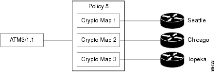
A VPN connection is an association between a router interface and an IPSec policy. The building block of an IPSec policy is the crypto map. A crypto map specifies the following: a transform set and other parameters to govern encryption, the identity of one or more peers, and an IPSec rule that specifies which traffic will be encrypted. An IPSec policy can contain multiple crypto maps.
The following diagram shows an interface (ATM 3/1.1) associated with an IPSec policy. The policy has three crypto maps, each specifying a different peer system. The ATM 3/1.1 interface is thus associated with three VPN connections.
A crypto map can specify more than one peer for a connection. This may be done to provide redundancy. The following diagram shows the same interface and policy, but crypto map CM-3 specifies two peers: Topeka and Lawrence.
A router interface can be associated with only one IPSec policy. However, an IPSec policy can be associated with multiple router interfaces, and a crypto map can specify more than one peer for a connection. The following diagram shows two router interfaces associated with a policy, and a crypto map specifying two peers.
There are six VPN connections in this configuration, as both Dialer 3 and Serial 1/1 have connections to Seattle, Chicago, Topeka, and Lawrence. SDM would show the links to Topeka and Lawrence as one connection for both interfaces.
More About IKE
IKE handles the following tasks:
•
Authentication
Authentication is arguably the most important task that IKE accomplishes, and it certainly is the most complicated. Whenever you negotiate something, it is of utmost importance that you know with whom you are negotiating. IKE can use one of several methods to authenticate negotiating parties to each other.
•
•
•
Note
Session Negotiation
During session negotiation, IKE allows parties to negotiate how they will conduct authentication and how they will protect any future negotiations (that is, IPSec tunnel negotiation). The following items are negotiated:
•
•
–
–
Key Exchange
IKE uses the negotiated key-exchange method (see "Session Negotiation" above) to create enough bits of cryptographic keying material to secure future transactions. This method ensures that each IKE session will be protected with a new, secure set of keys.
Authentication, session negotiation, and key exchange constitute phase 1 of an IKE negotiation.
IPSec Tunnel Negotiation and Configuration
After IKE has finished negotiating a secure method for exchanging information (phase 1), we use IKE to negotiate an IPSec tunnel. This is accomplished in IKE phase 2. In this exchange, IKE creates fresh keying material for the IPSec tunnel to use (either using the IKE phase 1 keys as a base or by performing a new key exchange). The encryption and authentication algorithms for this tunnel are also negotiated.
More About IKE Policies
When the IKE negotiation begins, IKE looks for an IKE policy that is the same on both peers. The peer that initiates the negotiation will send all its policies to the remote peer, and the remote peer will try to find a match. The remote peer looks for a match by comparing its own highest priority policy against the other peer's received policies. The remote peer checks each of its policies in order of its priority (highest first) until a match is found.
A match is made when both policies from the two peers contain the same encryption, hash, authentication, and Diffie-Hellman parameter values, and when the remote peer's policy specifies a lifetime less than or equal to the lifetime in the policy being compared. If the lifetimes are not identical, the shorter lifetime-from the remote peer's policy will be used.
Allowable Transform Combinations
To define a transform set, you specify one to three transforms. Each transform represents an IPSec security protocol ( AH or ESP) plus the algorithm that you want to use. When the particular transform set is used during negotiations for IPSec security associations, the entire transform set (the combination of protocols, algorithms, and other settings) must match a transform set at the remote peer.
The following table lists the acceptable transform combination selections for the AH and ESP protocols.
The following table describes each of the transforms.
Examples
The following are examples of permissible transform combinations:
•
•
•
•
•
Reasons Why a Serial Interface or Subinterface Configuration May Be Read-Only
A previously configured Serial interface or subinterface will be read-only and will not be configurable in the following cases:
•
•
•
•
•
•
•
•
•
•
•
•
•
•
Reasons Why an ATM Interface or Subinterface Configuration May Be Read-Only
A previously configured ATM interface or subinterface will be read-only and will not be configurable in the following cases:
•
•
•
•
•
•
•
•
•
•
•
•
•
•
•
•
•
•
•
Reasons Why an Ethernet Interface Configuration May Be Read-Only
A previously configured Ethernet LAN or WAN interface or will be read-only and will not be configurable in the following cases:
•
Reasons Why an ISDN BRI Interface Configuration May Be Read-Only
A previously configured ISDN BRI interface will be read-only and will not be configurable in the following cases:
•
•
•
•
•
•
•
•
•
•
•
•
–
–
–
–
–
–
–
–
Reasons Why an Analog Modem Interface Configuration May Be Read-Only
A previously configured analog modem interface or will be read-only and will not be configurable in the following cases:
•
•
•
•
•
•
•
•
•
•
•
•
•
–
–
–
–
–
–
–
–
Firewall Policy Use Case Scenario
In this scenario, a firewall and DMZ network have been created using the SDM Firewall wizard. The user has added a webserver to the DMZ network, and needs to allow web traffic into the DMZ network.
These are the interfaces used in this scenario:
•
•
•
The following sections show how to use the Firewall Policy window to examine the rules applied to router interfaces with the Firewall wizard or Rules windows and how to modify access and inspection rules.
•
•
•
•
Examining Originating Traffic: From Interface Fast Ethernet 0/0; To Interface Serial 1/0
In this configuration, there is a firewall filtering traffic entering the router on the Serial 1/0 interface bound for the network connected to the Fast Ethernet 0/0 interface. The following traffic diagram shows that an access rule and an inspection rule have been applied to inbound traffic on the Fast Ethernet 0/0 interface, and that an access rule has been applied to inbound traffic on Serial 1/0.
In this diagram, the firewall icon indicates that a firewall is active between Fast Ethernet 0/0 and Serial 1/0. This is based on the presence of the inspection rule applied to Fast Ethernet 0/0, and the access rule applied to inbound traffic on Serial 1/0. Although an access rule has been applied to Fast Ethernet 0/0, it is not necessary for the firewall.
The following illustration shows entries for the inspection rule on Fast Ethernet 0/0.
These entries specify which traffic inbound on Fast Ethernet 0/0 will be inspected as it enters the router. Returning traffic matching the inspection criteria will be allowed into the router if it is associated with a session initiated on Fast Ethernet 0/0's network.
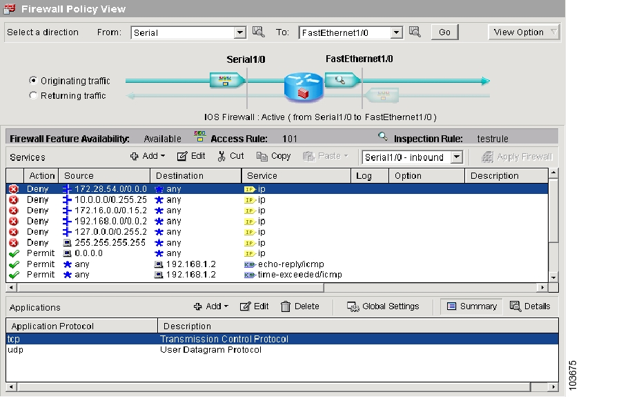
Examining Returning Traffic: From Interface Ethernet 0/0; To Interface Serial 1/0
Clicking the Returning traffic button displays the access rule for inbound traffic on Serial 1/0.
These are the entries that protect the network attached to Fast Ethernet 0/0. The Deny entries filter IP traffic from specific networks. There is an explicit permit all entry for IP traffic, and two Permit entries for ICMP traffic bound for specific hosts.
The Applications area would still display the inspection rule applied to Fast Ethernet 0/0 inbound, even though returning traffic was selected.
Examining Originating Traffic: From: Serial 1/0; To: Ethernet 1/0
In order to view the policy for traffic bound for the DMZ interface, the user can select Swap From and To interfaces from the View Options menu, and select Fast Ethernet 1/0 in the To interface list. Doing so makes Serial 1/0 the From interface and Fast Ethernet 1/0 the To interface.
The Services area shows that certain types of ICMP traffic have been permitted.
Allowing www Traffic to DMZ Interface
The method shown in this section can also be used when there is no DMZ network, but you want to allow a certain type of traffic onto your trusted network.
In order to allow www traffic to the hosts 10.10.10.1 and 10.10.10.2 in the DMZ network, the user creates 2 entries using the Add button. In the Add an Extended Rule Entry dialog, the destination host IP addresses are specified, the TCP protocol is chosen, the source port any is chosen, and the destination port www is chosen. The two new permit entries are the second and third entries from the last entry.
DMVPN Configuration Recommendations
This help topic contains recommendations on how you should proceed when configuring routers in a DMVPN.
Configure the Hub First
It is important to configure the hub first because spokes must be configured using information about the hub. If you are configuring a hub, you can use the Spoke Configuration feature available in the Summary window to generate a text file that contains a procedure that you can send to spoke administrators so that they can configure the spokes with the correct hub information. If you are configuring a spoke, you must obtain the correct information about the hub before you begin.
Assigning Spoke Addresses
All routers in the DMVPN must be in the same subnet. Therefore, the hub administrator must assign addresses in the subnet to the spoke routers so that address conflicts do not occur, and so that everyone is using the same subnet mask.
Recommendations for Configuring Routing Protocols for DMVPN
The following are guidelines that you should note when configuring routing protocols for DMVPN. You can choose to ignore these guidelines, but SDM has not been tested in scenarios outside the guidelines and may not be able to let you edit configurations within SDM after you enter them.
These recommendations are listed in best-choice order:
•
•
•
•
Using Interfaces with Dialup Configurations
Selecting an interface that uses a dialup connection may cause the connection to be always up. You can examine supported interfaces in Interfaces and Connections to determine if a dialup connection, such as an ISDN or Async connection has been configured for the physical interface you selected.
Ping the Hub Before You Start Spoke Configuration
Before configuring a spoke router, you should test connectivity to the hub by issuing the ping command. If the ping does not succeed, you must configure a route to the hub.
SDM White Papers
A number of white papers are available that describe how SDM can be used. These white papers are available at the following link.
http://www.cisco.com/univercd/cc/td/doc/product/software/sdm/appnote/index.htm
![]()
![]()
![]()
![]()
![]()
![]()
![]()
![]()
Posted: Fri Oct 7 14:00:20 PDT 2005
All contents are Copyright © 1992--2005 Cisco Systems, Inc. All rights reserved.
Important Notices and Privacy Statement.