cc/td/doc/product/ong/acdcpwr
hometocprevnextglossaryfeedbacksearchhelp
PDF

Table Of Contents

Replacing a Cisco AC/DC Power System Controller Tray

Safety Information

Remove the Controller Tray

Install the Replacement Controller Tray

Obtaining Documentation

Cisco.com

Ordering Documentation

Documentation Feedback

Obtaining Technical Assistance

Cisco Technical Support Website

Submitting a Service Request

Definitions of Service Request Severity

Obtaining Additional Publications and Information


Replacing a Cisco AC/DC Power System Controller Tray


This document explains how to replace a controller tray in the Cisco AC/DC Power System. It contains the following sections:

Safety Information

Remove the Controller Tray

Install the Replacement Controller Tray

Obtaining Documentation

Documentation Feedback

Obtaining Technical Assistance

Obtaining Additional Publications and Information

Safety Information


Warning Only trained and qualified personnel should be allowed to install, replace, or service this equipment. Statement 1030


Warning This unit is intended for installation in restricted access areas. A restricted access area can be accessed only through the use of a special tool, lock and key, or other means of security. Statement 1017


Warning Before working on a chassis or working near power supplies, unplug the power cord on AC units; disconnect the power at the circuit breaker on DC units. Statement 12


Warning Before working on equipment that is connected to power lines, remove jewelry (including rings, necklaces, and watches). Metal objects will heat up when connected to power and ground and can cause serious burns or weld the metal object to the terminals. Statement 43


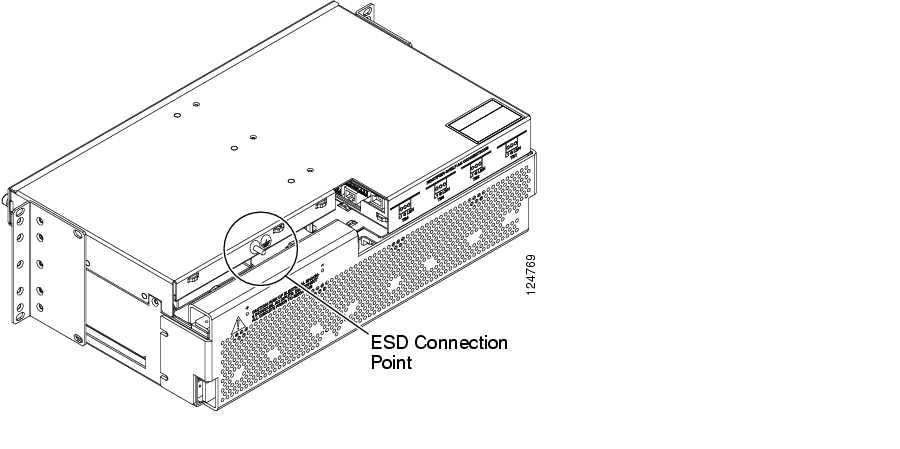
An ESD wrist strap is included with the system to protect sensitive electronics and should be connected to a bare metal surface to act as a ground. This ensures that all components have the same charge. An ESD wrist strap should be used when working with internal components that are installed in the shelf. If rear access is available, the wrist strap can connect at the rear of the system shelf as shown in Figure 1.

Figure 1 ESD Wrist Strap Connection Point

Keep the system area clear and dust-free during and after the installation.

Always check for possible hazards before beginning work.

Remove the Controller Tray


Step 1 Locate the controller faceplate on the system shelf.

Step 2 To access the sliding controller tray, remove the controller faceplate by loosening the two front thumbscrews ( Figure 2).

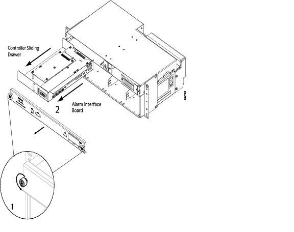
Figure 2 Removing the Controller Faceplate

Step 3 Slide the controller tray out and away from the system shelf to access the connections on the Alarm Interface Board ( Figure 2 #2).

Step 4 Remove the terminal block on the Alarm Interface Board ( Figure 3).

Figure 3 Inserting or Removing the Terminal Block

Step 5 Remove the following alarm cable connections in ( Figure 4 or Figure 5 #2, depending on your controller hardware).

J16 terminal block

J15 terminal block

J14/J13 terminal blocks


Note If alarm cables are not labeled with the jumper number, label the cables with the appropriate jumper number: J16, J15, J14 (1,2,3), and J14 (4,5,6)/J13 for the system without an LCD display..


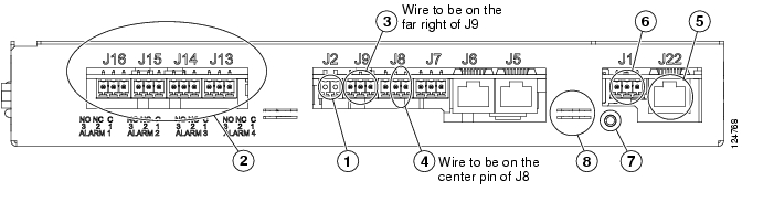
Figure 4 Removing the Alarm Interface Board Cable on the First Version of the Controller Hardware

Figure 5 Removing the Alarm Interface Board Cable on the Second Version of the Controller Hardware

Step 6 Remove the intra-shelf communications cabling:

J9 terminal block ( Figure 5 or Figure 4 #3)

J8 terminal block ( Figure 5 or Figure 4 #4)

J1 Ethernet cable ( Figure 5 or Figure 4 #5)

J1 terminal block ( Figure 5 or Figure 4 #6)


Note When the controller is disconnected from the system, the rectifiers return to their default voltage (53.5 VDC). The change in voltage will not have an effect on the load. The output will remain at 53.5 VDC until the new controller tray is installed and activated.


Step 7 Remove the controller tray ground connection by removing the Phillips head screw ( Figure 5 or Figure 4 #7).

Step 8 Remove the wire tie holding the controller tray in the system shelf ( Figure 5 or Figure 4 #8).

Step 9 Pull the controller tray out of the system shelf.


Install the Replacement Controller Tray


Step 1 Place the controller tray in the system shelf.

Step 2 Reinstall the controller tray ground connection by connecting the Phillips head screw ( Figure 5 or Figure 4 #7).

Step 3 Use a new wire tie to replace the one that was removed in the previous procedure.

Step 4 Reconnect intra-shelf communications cabling ( Figure 3); cables are labeled with the appropriate jumper number:

J9 terminal block ( Figure 5 or Figure 4 #3)

J8 terminal block ( Figure 5 or Figure 4 #4)

J1 Ethernet cable ( Figure 5 or Figure 4 #5)

J1 terminal block ( Figure 5 or Figure 4 #6)

Step 5 Reconnect the following alarm cable connections ( Figure 5 or Figure 4 #2).

J16 terminal block

J15 terminal block

J14/J13 terminal blocks

Step 6 Slide the controller tray back into the system shelf.

Step 7 Replace the controller faceplate by attaching it to the system shelf and tightening the two front thumbscrews.

Step 8 After installing the controller, the controller and rectifier LEDs will start to blink. It may take a few minutes for the controller to communicate with all rectifiers. At this point, all rectifier output voltages will return to the programmed level. Load output is not affected while the LEDs are blinking.


Obtaining Documentation

Cisco documentation and additional literature are available on Cisco.com. Cisco also provides several ways to obtain technical assistance and other technical resources. These sections explain how to obtain technical information from Cisco Systems.

Cisco.com

You can access the most current Cisco documentation at this URL:

http://www.cisco.com/univercd/home/home.htm

You can access the Cisco website at this URL:

http://www.cisco.com

You can access international Cisco websites at this URL:

http://www.cisco.com/public/countries_languages.shtml

Ordering Documentation

You can find instructions for ordering documentation at this URL:

http://www.cisco.com/univercd/cc/td/doc/es_inpck/pdi.htm

You can order Cisco documentation in these ways:

Registered Cisco.com users (Cisco direct customers) can order Cisco product documentation from the Ordering tool:

http://www.cisco.com/en/US/partner/ordering/index.shtml

Nonregistered Cisco.com users can order documentation through a local account representative by calling Cisco Systems Corporate Headquarters (California, USA) at 408 526-7208 or, elsewhere in North America, by calling 1 800 553-NETS (6387).

Documentation Feedback

You can send comments about technical documentation to bug-doc@cisco.com.

You can submit comments by using the response card (if present) behind the front cover of your document or by writing to the following address:

Cisco Systems
Attn: Customer Document Ordering
170 West Tasman Drive
San Jose, CA 95134-9883

We appreciate your comments.

Obtaining Technical Assistance

For all customers, partners, resellers, and distributors who hold valid Cisco service contracts, Cisco Technical Support provides 24-hour-a-day, award-winning technical assistance. The Cisco Technical Support Website on Cisco.com features extensive online support resources. In addition, Cisco Technical Assistance Center (TAC) engineers provide telephone support. If you do not hold a valid Cisco service contract, contact your reseller.

Cisco Technical Support Website

The Cisco Technical Support Website provides online documents and tools for troubleshooting and resolving technical issues with Cisco products and technologies. The website is available 24 hours a day, 365 days a year, at this URL:

http://www.cisco.com/techsupport

Access to all tools on the Cisco Technical Support Website requires a Cisco.com user ID and password. If you have a valid service contract but do not have a user ID or password, you can register at this URL:

http://tools.cisco.com/RPF/register/register.do


Note Use the Cisco Product Identification (CPI) tool to locate your product serial number before submitting a web or phone request for service. You can access the CPI tool from the Cisco Technical Support Website by clicking the Tools & Resources link under Documentation & Tools. Choose Cisco Product Identification Tool from the Alphabetical Index drop-down list, or click the Cisco Product Identification Tool link under Alerts & RMAs. The CPI tool offers three search options: by product ID or model name; by tree view; or for certain products, by copying and pasting show command output. Search results show an illustration of your product with the serial number label location highlighted. Locate the serial number label on your product and record the information before placing a service call.


Submitting a Service Request

Using the online TAC Service Request Tool is the fastest way to open S3 and S4 service requests. (S3 and S4 service requests are those in which your network is minimally impaired or for which you require product information.) After you describe your situation, the TAC Service Request Tool provides recommended solutions. If your issue is not resolved using the recommended resources, your service request is assigned to a Cisco TAC engineer. The TAC Service Request Tool is located at this URL:

http://www.cisco.com/techsupport/servicerequest

For S1 or S2 service requests or if you do not have Internet access, contact the Cisco TAC by telephone. (S1 or S2 service requests are those in which your production network is down or severely degraded.) Cisco TAC engineers are assigned immediately to S1 and S2 service requests to help keep your business operations running smoothly.

To open a service request by telephone, use one of the following numbers:

Asia-Pacific: +61 2 8446 7411 (Australia: 1 800 805 227)
EMEA: +32 2 704 55 55
USA: 1 800 553-2447

For a complete list of Cisco TAC contacts, go to this URL:

http://www.cisco.com/techsupport/contacts

Definitions of Service Request Severity

To ensure that all service requests are reported in a standard format, Cisco has established severity definitions.

Severity 1 (S1)—Your network is "down," or there is a critical impact to your business operations. You and Cisco will commit all necessary resources around the clock to resolve the situation.

Severity 2 (S2)—Operation of an existing network is severely degraded, or significant aspects of your business operation are negatively affected by inadequate performance of Cisco products. You and Cisco will commit full-time resources during normal business hours to resolve the situation.

Severity 3 (S3)—Operational performance of your network is impaired, but most business operations remain functional. You and Cisco will commit resources during normal business hours to restore service to satisfactory levels.

Severity 4 (S4)—You require information or assistance with Cisco product capabilities, installation, or configuration. There is little or no effect on your business operations.

Obtaining Additional Publications and Information

Information about Cisco products, technologies, and network solutions is available from various online and printed sources.

Cisco Marketplace provides a variety of Cisco books, reference guides, and logo merchandise. Visit Cisco Marketplace, the company store, at this URL:

http://www.cisco.com/go/marketplace/

The Cisco Product Catalog describes the networking products offered by Cisco Systems, as well as ordering and customer support services. Access the Cisco Product Catalog at this URL:

http://cisco.com/univercd/cc/td/doc/pcat/

Cisco Press publishes a wide range of general networking, training and certification titles. Both new and experienced users will benefit from these publications. For current Cisco Press titles and other information, go to Cisco Press at this URL:

http://www.ciscopress.com

Packet magazine is the Cisco Systems technical user magazine for maximizing Internet and networking investments. Each quarter, Packet delivers coverage of the latest industry trends, technology breakthroughs, and Cisco products and solutions, as well as network deployment and troubleshooting tips, configuration examples, customer case studies, certification and training information, and links to scores of in-depth online resources. You can access Packet magazine at this URL:

http://www.cisco.com/packet

iQ Magazine is the quarterly publication from Cisco Systems designed to help growing companies learn how they can use technology to increase revenue, streamline their business, and expand services. The publication identifies the challenges facing these companies and the technologies to help solve them, using real-world case studies and business strategies to help readers make sound technology investment decisions. You can access iQ Magazine at this URL:

http://www.cisco.com/go/iqmagazine

Internet Protocol Journal is a quarterly journal published by Cisco Systems for engineering professionals involved in designing, developing, and operating public and private internets and intranets. You can access the Internet Protocol Journal at this URL:

http://www.cisco.com/ipj

World-class networking training is available from Cisco. You can view current offerings at this URL:

http://www.cisco.com/en/US/learning/index.html


hometocprevnextglossaryfeedbacksearchhelp

Posted: Fri Jun 16 19:21:37 PDT 2006
All contents are Copyright © 1992--2006 Cisco Systems, Inc. All rights reserved.
Important Notices and Privacy Statement.