|
|

Table Of Contents
Cisco AC/DC Power System, Release 1.0
Install the Cisco AC/DC Power System
Install Shelves in a Rack/Cabinet
Install Communications Cabling
Install Circuit Breakers on Large Systems
Install Load-and-Return Connections
Obtaining Technical Assistance
Cisco Technical Support Website
Definitions of Service Request Severity
Obtaining Additional Publications and Information
Quick Install Guide
Cisco AC/DC Power System, Release 1.0
This guide provides basic instructions for installing the Cisco AC/DC Power System. Use this guide as a general reference when performing a new installation. For more detailed installation instructions, see the Cisco AC/DC Power System User Guide, Release 1.0.
Warning
Before working on a chassis or working near power supplies, unplug the power cord on AC units; disconnect the power at the circuit breaker on DC units. Statement 12
Warning
Warning
Warning
1 Installation Checklist
The following table is an installation checklist:
•
•
Warning
•
•
•
•
•
•
•
2 Installation Materials
Several items are needed to complete installation of the Cisco AC/DC Power System. Some items are supplied by Cisco and some are to be supplied by the user. The following are materials supplied by Cisco with the system shelf:
•
•
•
•
•
•
•
•
•
•
•
•
The following materials are supplied with the optional 1 RU Distribution Shelf:
•
•
•
•
•
•
•
The following materials and tools are required but not supplied with the Cisco AC/DC Power System:
•
•
•
•
•
•
Tools:
•
•
•
•
3 Install the Cisco AC/DC Power System
Install Ear Mounts
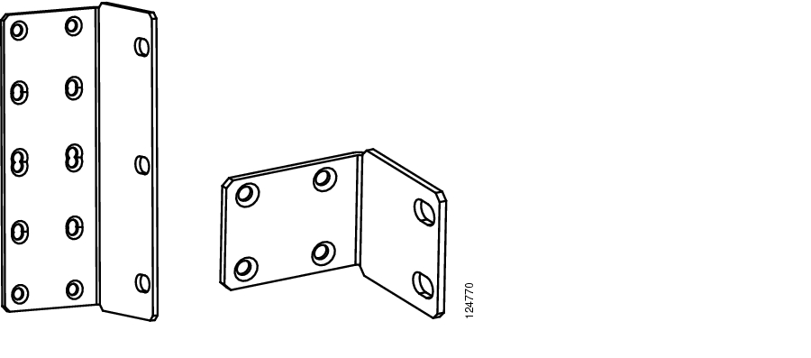
Ear mounts come mounted on the shelf and support 19in. and 23in. IEC and ANSI standards. For 23in. shelves, ears should be removed, reversed and reinstalled. Two additional plates are also included to accommodate ETSI racks ( Figure 1). To install ETSI mounting ears, remove existing ears and attach ETSI mounting ears using included hardware.
Figure 1 Ear Mounts
Install Shelves in a Rack/Cabinet
The system shelf should be installed first, followed by the 1 RU Distribution Shelf (if this option is included as part of the installation). If the install is going into a front access only environment, with no rear access after shelf installation, the AC cable installation and any rear wiring (communications cabling, ground cabling, alarm connections, and load connections) must be completed before the shelf is installed.
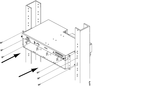
Install the System Shelf
Step 1
Step 2
Step 3
Step 4
Figure 2 Installing the Power System Shelf
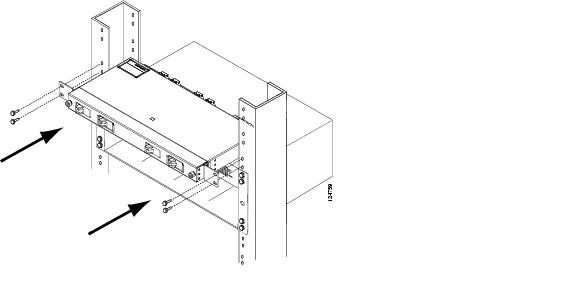
Install the 1 RU Distribution Shelf
Note
Step 1
Step 2
Figure 3 Installing the 1 RU Distribution Shelf
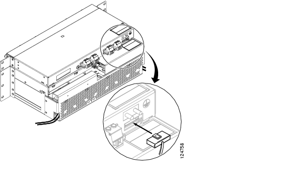
Install Communications Cabling
Intra-system shelf communications cabling is installed at the factory and requires no installation; however, the cabling must be installed in systems with the optional 1 RU Distribution Shelf.
Step 1
Step 2
Note
Figure 4 Installing Communications Cables
Install DC Power Cabling
In systems equipped with the 1 RU Distribution Shelf, follow the instructions below. For systems without the 1 RU Distribution Shelf, skip this procedure and go to the "Install Ground Cabling" procedure.
Step 1
Note
Step 2
Figure 5 Installing the DC Power Cable
Install Ground Cabling
Warning
The Equipment Rack/Cabinet, system shelf, and optional 1 RU Distribution Shelf need to be properly grounded to ensure the safe and efficient operation of the DC Power System.
To ground the equipment rack/cabinet, it should be bonded to the building principal ground busbar. Refer to the NEC, CEC, ANSI T1-333, ETSI 300-386-TC, and local codes for guidelines on bonding telecom DC power equipment to the building ground.
Ground the System Shelf
Step 1
Step 2
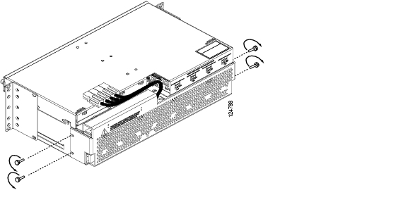
Figure 6 Removing the System Shelf Rear Cover
Step 3
Step 4
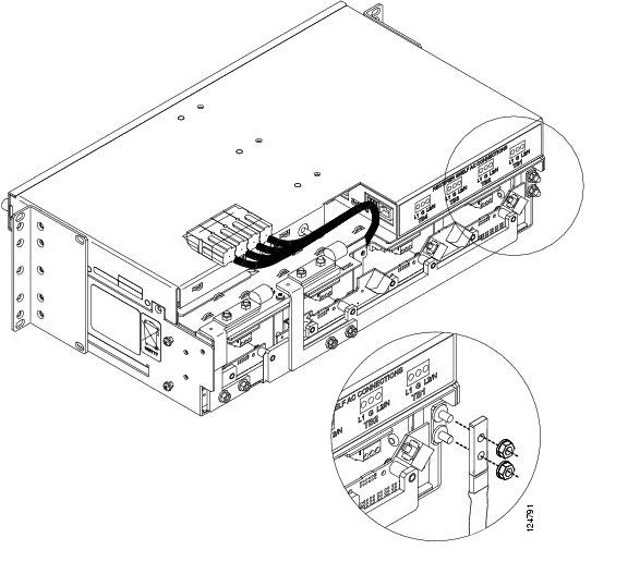
Figure 7 Grounding the System Shelf
Step 5
Ground the 1 RU Distribution Shelf
If a 1 RU Distribution Shelf is not installed, skip this procedure and continue with the "Install AC Power Cabling" procedure.
Step 1
Step 2
Step 3
Step 4
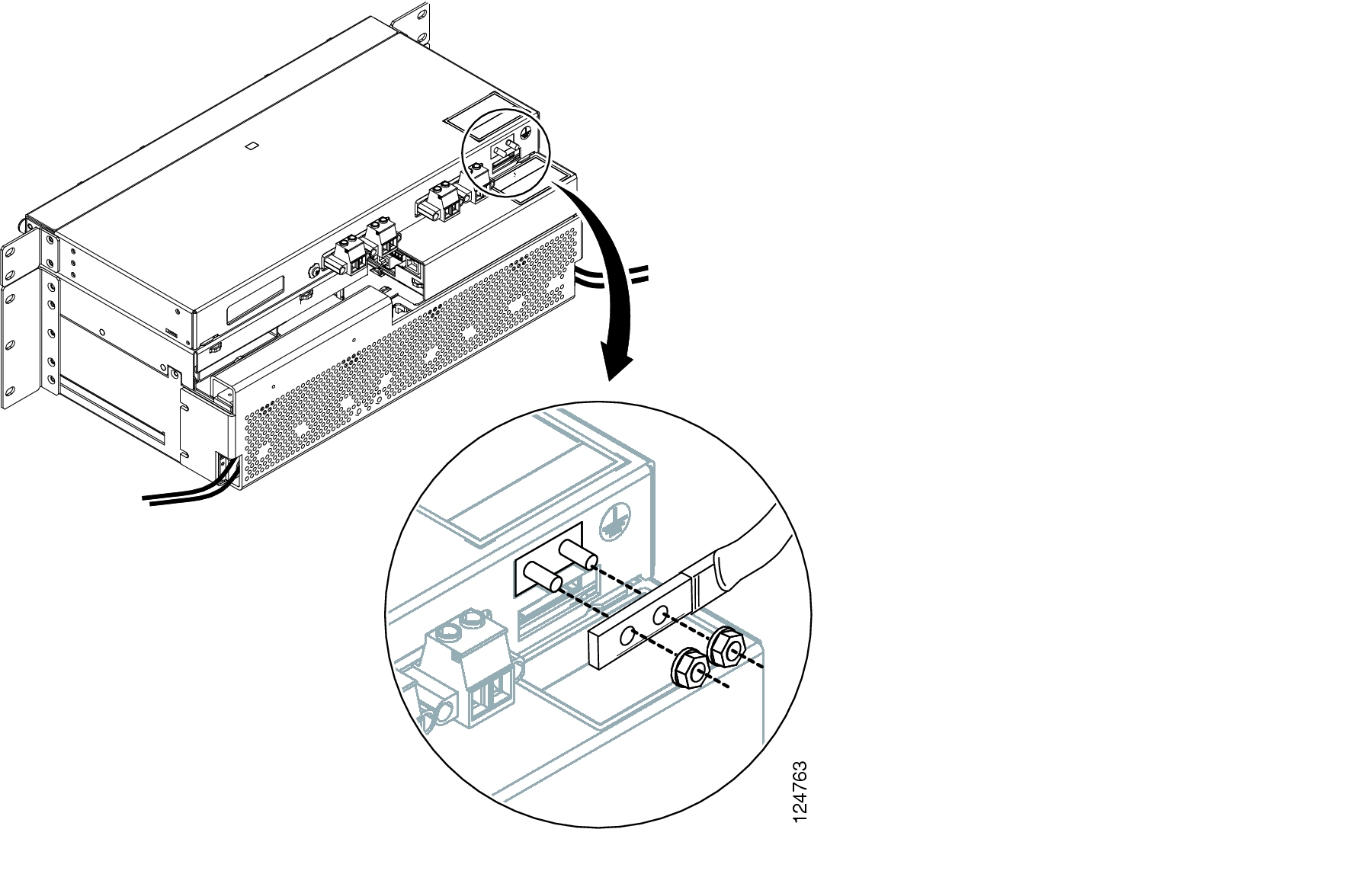
Figure 8 Grounding the 1 RU Distribution Shelf
Install AC Power Cabling
Step 1
Step 2
Step 3
Note
Step 4
Step 5
Step 6
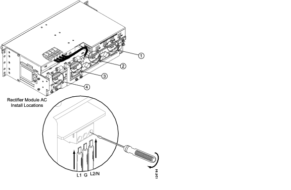
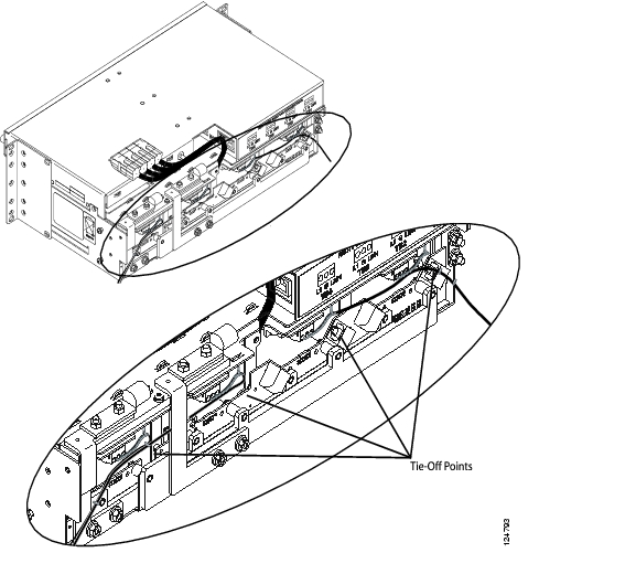
Figure 9 Installing AC Cabling
Step 7
Figure 10 AC Cable Routing
Step 8
Step 9
Step 10
Step 11
Install Rectifiers
To install rectifiers in the DC Power System:
Step 1
Step 2
Step 3
Step 4
Step 5
Figure 11 Installing a Rectifier
Step 6
Step 7
Figure 12 Removing a Blank Rectifier Faceplate
Step 8
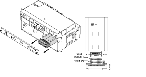
Install Circuit Breakers on Large Systems
Large systems equipped with the 1 RU DC Distribution Shelf require the installation of circuit breakers to ensure proper system protection. The 1 RU Distribution Shelf is shipped with two circuit breakers installed for use in medium systems.
To install circuit breakers in a large system:
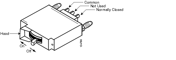
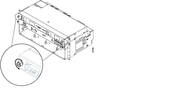
Step 1
Figure 13 Breaker On/Off Positions
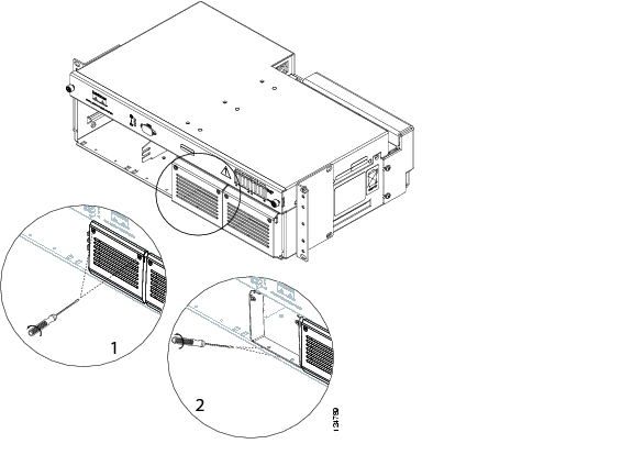
Step 2
Figure 14 Removing the 1 RU Distribution Faceplate
Step 3
Step 4
Step 5
Table 1 Circuit Breaker Positions
n/a
n/a
n/a
n/a
X
X
X
X
X
X
1 Future Upgrade
2 Future Upgrade
Step 6
Step 7
Step 8
Figure 15 Installing a Circuit Breaker
Install Alarm Cables
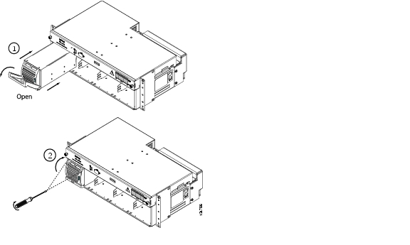
To install alarm cabling in the DC Power System:
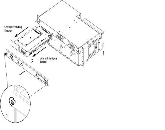
Step 1
Figure 16 Removing the Controller Faceplate
Step 2
Step 3
Figure 17 Installing Alarm Cable
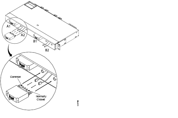
Note
Figure 18 Alarm Board Connections
Note
Step 4
Table 2 Alarm Designations
Low Voltage
X
Mains Error
X
Module Failure
X
Fuse/Circuit Breaker Fail
X
Step 5
Step 6
Step 7
Step 8
Install Load-and-Return Connections
This section explains how to install 1 RU Distribution Shelf and GMT load-and-return connections.
Install the 1 RU Distribution Shelf Load-and-Return Connections
The following section is for systems that use the 1 RU Distribution Shelf. For systems without the distribution shelf, skip this procedure and go to the "Install GMT Load-and-Return Connections" procedure.
Step 1
Table 3 Load Connection Wire Gauge
Breaker Load (up to 30A)
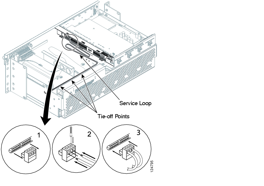
Step 2
Step 3
Step 4
Figure 19 Installing the 1 RU Load
Step 5
Step 6
Step 7
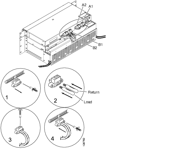
Install GMT Load-and-Return Connections
Step 1
Figure 20 GMT Fuse Block Location
Step 2
Table 4 GMT Load Connection Wire Gauge
22 AWG (0.34mm≤)
18 AWG (0.75mm≤)
14 AWG (2.5mm≤)
14 AWG (2.5mm≤)
Figure 21 Routing GMT Fuse Load Cables
Step 3
Step 4
Note
Figure 22 Installing GMT Fuses
4 Commission the System
The following section should be used to power-up the system for the first time.
Step 1
Step 2
Step 3
5 Obtaining Documentation
Cisco documentation and additional literature are available on Cisco.com. Cisco also provides several ways to obtain technical assistance and other technical resources. These sections explain how to obtain technical information from Cisco Systems.
Cisco.com
You can access the most current Cisco documentation at this URL:
http://www.cisco.com/univercd/home/home.htm
You can access the Cisco website at this URL:
You can access international Cisco websites at this URL:
http://www.cisco.com/public/countries_languages.shtml
Ordering Documentation
You can find instructions for ordering documentation at this URL:
http://www.cisco.com/univercd/cc/td/doc/es_inpck/pdi.htm
You can order Cisco documentation in these ways:
•
http://www.cisco.com/en/US/partner/ordering/index.shtml
•
6 Documentation Feedback
You can send comments about technical documentation to bug-doc@cisco.com.
You can submit comments by using the response card (if present) behind the front cover of your document or by writing to the following address:
Cisco Systems
Attn: Customer Document Ordering
170 West Tasman Drive
San Jose, CA 95134-9883We appreciate your comments.
7 Obtaining Technical Assistance
For all customers, partners, resellers, and distributors who hold valid Cisco service contracts, Cisco Technical Support provides 24-hour-a-day, award-winning technical assistance. The Cisco Technical Support Website on Cisco.com features extensive online support resources. In addition, Cisco Technical Assistance Center (TAC) engineers provide telephone support. If you do not hold a valid Cisco service contract, contact your reseller.
Cisco Technical Support Website
The Cisco Technical Support Website provides online documents and tools for troubleshooting and resolving technical issues with Cisco products and technologies. The website is available 24 hours a day, 365 days a year, at this URL:
http://www.cisco.com/techsupport
Access to all tools on the Cisco Technical Support Website requires a Cisco.com user ID and password. If you have a valid service contract but do not have a user ID or password, you can register at this URL:
http://tools.cisco.com/RPF/register/register.do
Note
Submitting a Service Request
Using the online TAC Service Request Tool is the fastest way to open S3 and S4 service requests. (S3 and S4 service requests are those in which your network is minimally impaired or for which you require product information.) After you describe your situation, the TAC Service Request Tool provides recommended solutions. If your issue is not resolved using the recommended resources, your service request is assigned to a Cisco TAC engineer. The TAC Service Request Tool is located at this URL:
http://www.cisco.com/techsupport/servicerequest
For S1 or S2 service requests or if you do not have Internet access, contact the Cisco TAC by telephone. (S1 or S2 service requests are those in which your production network is down or severely degraded.) Cisco TAC engineers are assigned immediately to S1 and S2 service requests to help keep your business operations running smoothly.
To open a service request by telephone, use one of the following numbers:
Asia-Pacific: +61 2 8446 7411 (Australia: 1 800 805 227)
EMEA: +32 2 704 55 55
USA: 1 800 553-2447For a complete list of Cisco TAC contacts, go to this URL:
http://www.cisco.com/techsupport/contacts
Definitions of Service Request Severity
To ensure that all service requests are reported in a standard format, Cisco has established severity definitions.
Severity 1 (S1)—Your network is "down," or there is a critical impact to your business operations. You and Cisco will commit all necessary resources around the clock to resolve the situation.
Severity 2 (S2)—Operation of an existing network is severely degraded, or significant aspects of your business operation are negatively affected by inadequate performance of Cisco products. You and Cisco will commit full-time resources during normal business hours to resolve the situation.
Severity 3 (S3)—Operational performance of your network is impaired, but most business operations remain functional. You and Cisco will commit resources during normal business hours to restore service to satisfactory levels.
Severity 4 (S4)—You require information or assistance with Cisco product capabilities, installation, or configuration. There is little or no effect on your business operations.
8 Obtaining Additional Publications and Information
Information about Cisco products, technologies, and network solutions is available from various online and printed sources.
•
http://www.cisco.com/go/marketplace/
•
http://cisco.com/univercd/cc/td/doc/pcat/
•
•
•
http://www.cisco.com/go/iqmagazine
•
•
![]()
![]()
![]()
![]()
![]()
![]()
![]()
![]()
Posted: Fri Jun 16 19:15:01 PDT 2006
All contents are Copyright © 1992--2006 Cisco Systems, Inc. All rights reserved.
Important Notices and Privacy Statement.