|
|

Table Of Contents
Create Optical Channel Circuits and Provisionable Patchcords
NTP-G151 Create, Delete, and Manage Optical Channel Client Connections
DLP-G104 Assign a Name to a Port
DLP-G345 Verify OCHCC Client Ports
DLP-G346 Provision Optical Channel Client Connections
DLP-G347 Delete Optical Channel Client Connections
DLP-G424 Edit an OCHCC Circuit Name
DLP-G394 Change an OCHCC Administrative State
DLP-G437 Set OCH Circuit Attributes
DLP-G438 Set OCH Routing Preferences
NTP-G178 Create, Delete, and Manage Optical Channel Trails
DLP-G395 Create an Optical Channel Trail
DLP-G418 Delete an Optical Channel Trail
DLP-G425 Edit an OCH Trail Circuit Name
DLP-G419 Change an OCH Trail Administrative State
NTP-G59 Create, Delete, and Manage Optical Channel Network Connections
DLP-G105 Provision Optical Channel Network Connections
DLP-G106 Delete Optical Channel Network Connections
DLP-G426 Edit an OCHNC Circuit Name
DLP-G420 Change an OCHNC Administrative State
NTP-G150 Upgrade Optical Channel Network Connections to Optical Channel Client Connections
DLP-G344 Verify Provisionable and Internal Patchcords
NTP-G183 Diagnose and Fix OCHNC and OCH Trail Circuits
NTP-G58 Locate and View Optical Channel Circuits
DLP-G100 Search for Optical Channel Circuits
DLP-G101 View Optical Channel Circuit Information
DLP-G102 Filter the Display of Optical Channel Circuits
DLP-G103 View Optical Channel Circuits on a Span
NTP-G184 Create a Provisionable Patchcord and DCN Extension
NTP-G181 Manage GE_XP and 10GE_XP Card SVLAN Databases
DLP-G421 Create and Store an SVLAN Database
DLP-G422 Load or Merge an SVLAN Database
DLP-G423 View OCH Trails that Support an SVLAN
NTP-G60 Create and Delete Overhead Circuits
DLP-G76 Provision GCC Terminations
DLP-G97 Provision a Proxy Tunnel
DLP-G98 Provision a Firewall Tunnel
DLP-G108 Change the Service State for a Port
DLP-G110 Create a User Data Channel Circuit
DLP-G112 Delete Overhead Circuits
NTP-G62 Create a J0 Section Trace
Create Optical Channel Circuits and Provisionable Patchcords
This chapter explains how to create Cisco ONS 15454 dense wavelength division multiplexing (DWDM) optical channel client connections (OCHCCs), optical channel network connections (OCHNCs), and optical trail circuits. The chapter also tells you how to create provisionable patchcords, upgrade OCHNCs to OCHCCs, how to manage SVLANs for the GE_XP and 10GE_XP cards, and how to manage overhead circuits.
Note
Unless otherwise specified, "ONS 15454" refers to both ANSI and ETSI shelf assemblies.
Before You Begin
Before performing any of the following procedures, investigate all alarms and clear any trouble conditions. Refer to the Cisco ONS 15454 DWDM Troubleshooting Guide as necessary.
This section lists the chapter procedures (NTPs). Turn to a procedure for applicable tasks (DLPs).
1.
2.
3.
4.
5.
6.
7.
8.
9.
10.
NTP-G151 Create, Delete, and Manage Optical Channel Client Connections
Note
Step 1
Step 2
Step 3
Note
Step 4
a.
b.
Step 5
Step 6
Step 7
Step 8
Step 9
Step 10
Stop. You have completed this procedure.
DLP-G104 Assign a Name to a Port
Step 1
Step 2
Step 3
Step 4
The port name can be up to 32 alphanumeric/special characters. The field is blank by default.
Step 5
Step 6
DLP-G345 Verify OCHCC Client Ports
Step 1
Step 2
Step 3
Step 4
Step 5
Step 6
DLP-G346 Provision Optical Channel Client Connections
Note
Note
Note
Note
Note
Step 1
Step 2
Step 3
Step 4
Step 5
•
•
•
Note
•
Note
Table 7-2 OCH C-Band Channels
1
30.3
195.9
1530.33
2
31.1
195.8
1531.12
3
31.9
195.7
1531.90
4
33.4
195.5
1532.68
5
32.6
195.6
1533.471
6
34.2
195.4
1534.25
7
35.0
195.3
1535.04
8
35.8
195.2
1535.82
0
36.1
195.1
1536.61
10
37.4
195
1537.401
11
38.1
194.9
1538.19
12
38.9
194.8
1538.98
13
39.7
194.7
1539.77
14
40.5
194.6
1540.56
15
41.3
194.5
1541.351
16
42.1
194.4
1542.14
17
42.9
194.3
1542.94
18
43.7
194.2
1543.73
19
44.5
194.1
1544.53
20
44.3
194
1545.321
21
46.1
193.9
1546.12
22
46.9
193.8
1546.92
23
47.7
193.7
1547.72
24
48.5
193.6
1548.51
25
49.3
193.5
1549.321
26
50.1
193.4
1550.12
27
50.9
193.3
1550.92
28
51.7
193.2
1551.72
29
52.5
193.1
1552.52
30
53.3
193
1553.331
31
54.1
192.9
1554.13
32
54.9
192.8
1544.94
33
55.7
192.7
1555.75
34
56.5
192.6
1556.55
35
57.3
192.5
1557.361
36
58.1
192.4
1558.17
37
58.9
192.3
1558.98
38
59.7
192.2
1559.79
39
60.6
192.1
1560.61
40
61.3
192
1561.421
1 Requires 40-channel MUX or WSS cards, and 40-channel DMX cards.
•
•
Figure 7-1 OCHCC Attributes Page
Step 6
•
•
Step 7
Step 8
If no nodes appear in the Node drop-down list, complete the following steps:
a.
b.
If these steps do not solve the problem, refer to your next level of support.
Step 9
Step 10
If no nodes appear in the Node drop-down list, complete the following steps:
a.
b.
If these steps do not solve the problem, refer to your next level of support.
Step 11
Step 12
Step 13
Step 14
Step 15
If the OCHCC status does not change to DISCOVERED within 2 to 3 minutes, contact your next level of support.
Step 16
DLP-G347 Delete Optical Channel Client Connections
Purpose
This task deletes DWDM OCHCC circuits.
Tools/Equipment
None
Prerequisite Procedures
Required/As Needed
As needed
Onsite/Remote
Onsite or remote
Security Level
Provisioning or higher
Note
Step 1
Step 2
Step 3
Step 4
Step 5
Step 6
Step 7
•
–
–
–
–
•
Note
Step 8
•
•
Step 9
a.
b.
c.
Step 10
Step 11
Step 12
DLP-G424 Edit an OCHCC Circuit Name
Purpose
This task changes the name of an OCHCC circuit.
Tools/Equipment
None
Prerequisite Procedures
G105 Provision Optical Channel Network Connections
Required/As Needed
As needed
Onsite/Remote
Onsite or remote
Security Level
Provisioning or higher
Step 1
Step 2
Step 3
Step 4
Step 5
Step 6
DLP-G394 Change an OCHCC Administrative State
Purpose
This task changes the administrative state of an OCHCC circuit.
Tools/Equipment
None
Prerequisite Procedures
G346 Provision Optical Channel Client Connections
Required/As Needed
As needed
Onsite/Remote
Onsite or remote
Security Level
Provisioning or higher
Step 1
Step 2
Step 3
Step 4
Step 5
•
•
Step 6
Step 7
Note
Step 8
DLP-G437 Set OCH Circuit Attributes
Step 1
•
–
–
–
–
Note
•
–
–
Step 2
DLP-G438 Set OCH Routing Preferences
Step 1
a.
b.
c.
Note
d.
–
–
–
Note
e.
f.
Step 2
NTP-G178 Create, Delete, and Manage Optical Channel Trails
Step 1
Step 2
Step 3
Step 4
Step 5
Step 6
Stop. You have completed this procedure.
DLP-G395 Create an Optical Channel Trail
Note
Step 1
Step 2
Step 3
Step 4
Step 5
•
•
•
•
•
•
•
Figure 7-2 OCH Trail Attributes Page
Step 6
Step 7
The source In and Out shelf (multishelf nodes only), slot, and port appear under the OTS Lines area.
Step 8
Step 9
The destination In and Out shelf (multishelf only), slot, and port appear under the OTS Lines area to show the destination in and out shelf, slots, and ports.
Step 10
Step 11
Step 12
Step 13
Step 14
Step 15
DLP-G418 Delete an Optical Channel Trail
Purpose
This task deletes DWDM OCH trail circuits.
Tools/Equipment
None
Prerequisite Procedures
Required/As Needed
As needed
Onsite/Remote
Onsite or remote
Security Level
Provisioning or higher
Note
Step 1
Step 2
Step 3
Step 4
Step 5
Step 6
Step 7
•
–
–
–
–
•
Note
Step 8
•
•
Step 9
a.
b.
c.
Step 10
Step 11
Step 12
DLP-G425 Edit an OCH Trail Circuit Name
Purpose
This task changes the name of an OCH trail circuit.
Tools/Equipment
None
Prerequisite Procedures
G105 Provision Optical Channel Network Connections
Required/As Needed
As needed
Onsite/Remote
Onsite or remote
Security Level
Provisioning or higher
Step 1
Step 2
Step 3
Step 4
Step 5
Step 6
DLP-G419 Change an OCH Trail Administrative State
Purpose
This task changes the administrative state of an OCH trail circuit.
Tools/Equipment
None
Prerequisite Procedures
G395 Create an Optical Channel Trail
Required/As Needed
As needed
Onsite/Remote
Onsite or remote
Security Level
Provisioning or higher
Step 1
Step 2
Step 3
Step 4
Step 5
•
•
Step 6
Step 7
Note
Step 8
NTP-G59 Create, Delete, and Manage Optical Channel Network Connections
Step 1
Step 2
Step 3
Step 4
Step 5
Step 6
Stop. You have completed this procedure.
DLP-G105 Provision Optical Channel Network Connections
Step 1
Step 2
Step 3
Step 4
Step 5
•
•
•
•
•
•
•
Figure 7-3 OCHNC Attributes Page
Step 6
Step 7
The source In and Out shelf (multishelf nodes only), slot, and port appear under the OTS Lines area.
Step 8
Step 9
The destination In and Out shelf (multishelf nodes only), slot, and port appear under the OTS Lines area.
Step 10
Step 11
Step 12
Step 13
DLP-G106 Delete Optical Channel Network Connections
Purpose
This task deletes DWDM OCHNC circuits.
Tools/Equipment
None
Prerequisite Procedures
Required/As Needed
As needed
Onsite/Remote
Onsite or remote
Security Level
Provisioning or higher
Note
Step 1
Step 2
Step 3
Step 4
Step 5
Step 6
Step 7
Step 8
If checked, the CTC Alerts confirmation dialog box will alert you when the OCHNC is deleted. During this time, you cannot perform other CTC functions. If you are deleting many OCHNCs, waiting for confirmation might take a few minutes. Circuits are deleted whether or not this check box is checked.
Note
Step 9
•
•
Step 10
a.
b.
c.
Step 11
Step 12
Step 13
DLP-G426 Edit an OCHNC Circuit Name
Purpose
This task changes the name of an OCHNC circuit.
Tools/Equipment
None
Prerequisite Procedures
G105 Provision Optical Channel Network Connections
Required/As Needed
As needed
Onsite/Remote
Onsite or remote
Security Level
Provisioning or higher
Step 1
Step 2
Step 3
Step 4
Step 5
Step 6
DLP-G420 Change an OCHNC Administrative State
Purpose
This task changes the administrative state of an OCHNC circuit.
Tools/Equipment
None
Prerequisite Procedures
G105 Provision Optical Channel Network Connections
Required/As Needed
As needed
Onsite/Remote
Onsite or remote
Security Level
Provisioning or higher
Step 1
Step 2
Step 3
Step 4
Step 5
•
•
Step 6
Step 7
Note
Step 8
NTP-G150 Upgrade Optical Channel Network Connections to Optical Channel Client Connections
Note
Note
Step 1
Step 2
Step 3
Step 4
Step 5
•
•
•
Step 6
•
•
Step 7
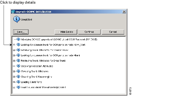
Step 8
a.
b.
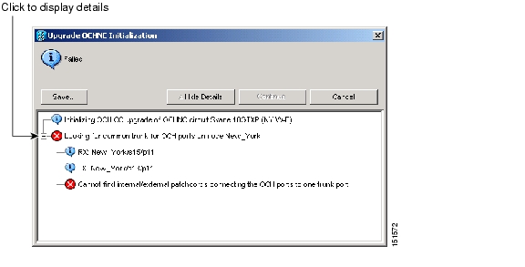
Figure 7-4 Upgrade OCHNC Initialization—Completed
Figure 7-5 Upgrade OCHNC Initialization—Failed
Step 9
Step 10
Step 11
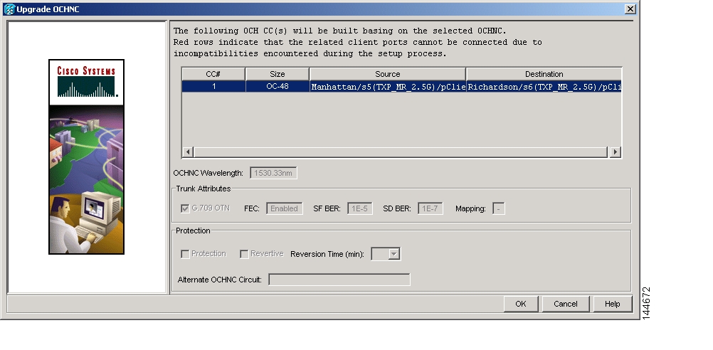
Tip
Figure 7-6 Upgrade OCHNC Dialog Box
Step 12
Stop. You have completed this procedure.
DLP-G344 Verify Provisionable and Internal Patchcords
Step 1
Step 2
Step 3
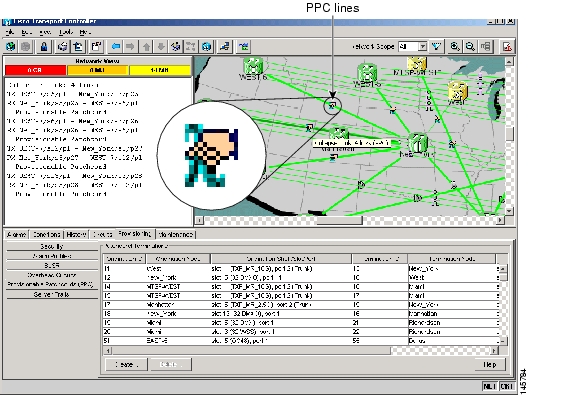
•
•
Figure 7-7 Viewing the Provisionable Patchcords Table
Step 4
Step 5
Step 6
Step 7
Step 8
Step 9
Step 10
NTP-G183 Diagnose and Fix OCHNC and OCH Trail Circuits
Purpose
This procedure checks nodes that are traversed by an OCHNC or OCH trail circuit to verify that all conditions required for bringing the circuit in service are in place. If not, the procedure identifies the invalid condition and provides links to the location in CTC where it can be fixed.
Tools/Equipment
None
Prerequisite Procedures
G105 Provision Optical Channel Network Connections, or
Required/As Needed
As needed
Onsite/Remote
Onsite or remote
Security Level
Provisioning or higher
Note
Step 1
Note
Step 2
Step 3
Step 4
Step 5
Step 6
Step 7
Step 8
•
•
Note
Table 7-4 Diagnostic and Fix Errors
Invalid connection state for "circuit name": administrative state
The circuit state is not valid. Click Fix to display the State tab of the Edit Circuit dialog box where you can change the circuit state using the "DLP-G419 Change an OCH Trail Administrative State" task or the "DLP-G420 Change an OCHNC Administrative State" task.
Invalid admin state: administrative state
The state of a port traversed by the circuit is not valid, for example, the port is in service. Click Fix to display the card view Provisioning tab, where you can change the port administrative state using the appropriate task for changing the optical line settings in Chapter 11, "Change DWDM Card Settings."
ANS couldn't regulate the port
ANS could not be regulated for the port. Click Fix to display the node view Provisioning > WDM-ANS > Port Status tab where you can launch ANS using the "NTP-G37 Run Automatic Node Setup" procedure on page 3-101.
APC couldn't regulate the port
APC could not be regulated for the port. Click Fix to display the network view Maintenance > APC tab. Double-click the domain to expand the view. Right-click the node/side and choose the end you want to view. APC information is displayed on the right side. Read any message that might explain the failure, or restart APC by completing the "DLP-G158 Enable Automatic Power Control" task on page 10-5.
APC regulation is running
Indicates that APC regulation is running and must be allowed to finish. Click Check to display the node view Maintenance > DWDM > APC tab where you can monitor the APC regulation.
APC is not enabled for this side.
APC is not enabled on an ONS 15454 side. Click Fix to display the network view Maintenance > APC tab where you can enable APC using the "DLP-G158 Enable Automatic Power Control" task on page 10-5.
Step 9
a.
b.
c.
Step 10
Stop. You have completed this procedure.
NTP-G58 Locate and View Optical Channel Circuits
Purpose
This procedure allows you to locate and view OCHNC, OCHCC and OCH trail circuits. You can also export circuit data into a text file.
Tools/Equipment
None
Prerequisite Procedures
G105 Provision Optical Channel Network Connections
Required/As Needed
As needed
Onsite/Remote
Onsite or remote
Security Level
Retrieve or higher
Step 1
Note
Step 2
Step 3
Step 4
Step 5
Step 6
Stop. You have completed this procedure.
DLP-G100 Search for Optical Channel Circuits
Step 1
•
•
•
Step 2
Step 3
Step 4
Step 5
•
•
•
•
Step 6
Step 7
Step 8
DLP-G101 View Optical Channel Circuit Information
Step 1
•
•
•
Note
Step 2
Note
•
•
Note
•
Note
•
•
•
•
•
•
•
•
•
–
–
–
Note
Step 3
DLP-G102 Filter the Display of Optical Channel Circuits
Step 1
•
•
•
Step 2
Step 3
a.
b.
•
•
•
•
•
•
•
•
•
•
Note
•
Note
The check boxes shown depend on the Type field selection. If you chose Any, all sizes are available. If you chose OCHNC as the circuit type, only Multi-rate, Equipment non specific, 2.5 Gbps FEC, 2.5 Gbps No FEC, 10 Gbps FEC, and 10 Gbps No FEC appear. If you choose OCHCC, only OCHCC is available. If you choose OCH Trail, only Equipment non specific is available.
Step 4
a.
b.
•
•
•
•
Step 5
Step 6
Step 7
DLP-G103 View Optical Channel Circuits on a Span
Step 1
Go to Network View. If you are already in network view, continue with Step 2.Step 2
Step 3
•
•
•
•
•
•
Step 4
NTP-G184 Create a Provisionable Patchcord and DCN Extension
Note
Note
Note
Note
Note
Step 1
•
•
Step 2
PPCs can be created in either node or network view. However, if you create the PPC in node view, the PPC origination ports will be restricted to the cards installed on the node. Therefore, choose node view only if you know that the PPC origination port resides on a card installed in the node.
Step 3
Figure 7-8 PPC Creation Wizard — PPC Attributes page
Step 4
•
•
•
Table 7-7 Provisionable Patchcord Ports
TXP cards
MXP cards
GE_XP
10GE_XP
ADM-10G
ITU-T line cards
Any trunk port
—
—
OPT-BST
OPT-BST-E
OPT-BST-L
—
COM RX1
LINE RX
LINE TX
—
OPT-AMP-17-C
OPT-AMP-L
—
COM RX2
COM TX3
LINE RX3
LINE TX3
—
OPT-PRE
—
COM RX4
COM TX4
—
OSC-CSM
—
COM RX1
LINE RX
LINE TX
—
32MUX
32MUX-O
40-MUX-C
—
—
Any CHAN RX port
32DMX
32DMX-L
32DMX-O
40-DMX-C
—
—
Any CHAN TX port
32WSS
32WSS-L
40-WSS-C
—
—
Any ADD port
40-WXC-C
—
COM RX
COM TX
—
MMU
—
EXP A RX
EXP A TX
—
1 Line nodes only
2 When Card Mode is OPT-PRE
3 When Card Mode is OPT-LINE
4 Line nodes with two OPT-PRE cards and no BST cards installed only
Step 5
•
•
Step 6
Step 7
Table 7-8 PPC Origination Fields
Node
Choose the node where the PPC will originate.
Yes
Yes
Yes
Side
Choose the side where the PPC will originate.
No
No
Yes
Shelf
(Multishelf only) Choose the shelf where the PPC will originate.
Yes
Yes
No
Slot
Choose the slot where the PPC will originate.
Yes
Yes
No
Port
Choose the port where the PPC will originate.
Yes
Yes
No
Tx Port
(Display only) The OTS RX port where the PPC will originate.
No
No
No
Rx Port
Choose the TX port where the PPC will originate.
No
No
No
Protection
(Display only) Displays the protection option chosen in Step 5, if applicable.
No
No
No
ID
Displays the ID automatically assigned to the PPC. You can enter a different ID, if needed. Patchcord IDs (0 through 32767) are used for your internal tracking and to help identify PPCs. All IDs must be unique within each node.
Yes
No
No
Tx ID
Displays the transmit ID automatically assigned to the PPC. You can enter a different Rx ID, if needed, 0 through 32767.
No
Yes
Yes
Rx ID
Displays the receive ID automatically assigned to the PPC. You can enter a different Tx ID, if needed, 0 through 32767.
No
Yes
Yes
Reset
Resets the ID or Tx ID and Rx ID fields to the automatically assigned ID, Rx ID, and Rx ID values.
Yes
Yes
Yes
Step 8
Step 9
Step 10
Step 11
Table 7-9 PPC Termination Fields
Node
Choose the node where the PPC will terminate.
Yes
Yes
Yes
Side
Choose the side where the PPC will terminate.
No
No
Yes
Shelf
(Multishelf only) Choose the shelf where the PPC will terminate.
Yes
Yes
No
Slot
Choose the slot where the PPC will terminate.
Yes
Yes
No
Port
Choose the port where the PPC will terminate.
Yes
No
No
Tx Port
Choose the RX port where the PPC will terminate.
No
Yes
No
Rx Port
Choose the TX port where the PPC will terminate.
No
No
No
Protection
(Display only) Displays the protection option chosen in Step 5, if applicable.
No
No
No
ID
Displays the ID automatically assigned to the PPC. You can enter a different ID, if needed. Patchcord IDs (0 through 32767) are used for your internal tracking and to help identify PPCs. All IDs must be unique within each node.
Yes
No
Yes
Rx ID
Displays the receive ID automatically assigned to the PPC. You can enter a different Tx ID, if needed, 0 through 32767.
No
Yes
No
Tx ID
Displays the transmit ID automatically assigned to the PPC. You can enter a different Rx ID, if needed, 0 through 32767.
No
Yes
No
Reset
Resets the ID or Tx ID and Rx ID fields to the automatically assigned ID, Rx ID, and Rx ID values.
Yes
Yes
Yes
Step 12
Step 13
Step 14
Stop. You have completed this procedure.
NTP-G181 Manage GE_XP and 10GE_XP Card SVLAN Databases
Step 1
Step 2
•
•
•
•
Stop. You have completed this procedure.
DLP-G421 Create and Store an SVLAN Database
Step 1
Step 2
Step 3
Step 4
Step 5
•
–
–
•
•
Step 6
Step 7
•
•
Step 8
Step 9
DLP-G422 Load or Merge an SVLAN Database
Step 1
Step 2
Step 3
•
•
Step 4
•
•
Step 5
Step 6
DLP-G423 View OCH Trails that Support an SVLAN
Step 1
Step 2
Step 3
Step 4
Step 5
Step 6
Step 7
•
•
•
Moving your mouse over the OCH trail end points displays the OCH trail source and destination nodes, shelves (for multishelf nodes), slots, and ports.
Step 8
NTP-G60 Create and Delete Overhead Circuits
Step 1
Step 2
Step 3
Step 4
Step 5
Step 6
Step 7
Stop. You have completed this procedure.
DLP-G76 Provision GCC Terminations
Step 1
Step 2
Step 3
Step 4
•
•
•
•
Note
Step 5
Step 6
Step 7
•
•
Step 8
a.
b.
–
–
–
–
–
Step 9
Step 10
DLP-G97 Provision a Proxy Tunnel
Note
Step 1
Step 2
Step 3
•
•
•
•
Step 4
Step 5
DLP-G98 Provision a Firewall Tunnel
Note
Step 1
Step 2
Step 3
•
•
•
•
Step 4
Step 5
DLP-G108 Change the Service State for a Port
Note
Step 1
Step 2
Step 3
•
•
For ANSI nodes, traffic is not passed on the port until the service state is changed to IS-NR; OOS-MA,MT; or Out-of-Service and Autonomous, Automatic In-Service (OOS-AU,AINS). For ETSI nodes, traffic is not passed on the port until the service state is changed to Unlocked-enabled; Locked-enabled,maintenance; or Unlocked-disabled,automaticInService.
•
•
Note
Step 4
Step 5
Step 6
Step 7
DLP-G109 Provision Orderwire
Step 1
Step 2
Step 3
Step 4
•
•
•
Caution
Step 5
Step 6
•
•
•
•
Step 7
Step 8
•
•
•
•
Step 9
Step 10
DLP-G110 Create a User Data Channel Circuit
Step 1
Step 2
Step 3
Step 4
•
•
Step 5
Step 6
•
•
•
•
Step 7
Step 8
•
•
•
•
Step 9
Step 10
DLP-G112 Delete Overhead Circuits
Caution
Step 1
Step 2
Step 3
Step 4
Step 5
Step 6
NTP-G62 Create a J0 Section Trace
Purpose
This procedure creates a repeated, fixed-length string of characters used to monitor interruptions or changes to traffic between nodes.
Tools/Equipment
One TXP or MXP card must be installed.
Prerequisite Procedures
NTP-G179 Install the TXP, MXP, GE_XP, 10GE_XP, and ADM-10G Cards, page 3-56
Required/As Needed
As needed (optional if path trace is set)
Onsite/Remote
Onsite or remote
Security Level
Provisioning or higher
Step 1
Step 2
Step 3
Step 4
Step 5
Step 6
Step 7
Step 8
Step 9
Step 10
Step 11
•
•
•
Caution
The expect and receive strings are updated every few seconds.
Stop. You have completed this procedure.
![]()
![]()
![]()
![]()
![]()
![]()
![]()
![]()
Posted: Mon Oct 29 01:18:28 PDT 2007
All contents are Copyright © 1992--2007 Cisco Systems, Inc. All rights reserved.
Important Notices and Privacy Statement.