|
|

Table Of Contents
1.2.1 Reversible Mounting Bracket
1.4.4 Alarm Interface Panel Replacement
1.5 Electrical Interface Assemblies
1.7.1 Twisted Pair Wire-Wrap Cables
1.7.2 Electrical Interface Adapters
1.11 Cable Routing and Management
1.11.2 Fiber Management Using the Tie-Down Bar
1.11.3 Coaxial Cable Management
1.11.4 DS-1 Twisted-Pair Cable Management
1.11.5 AMP Champ Cable Management
1.12.1 Wire-Wrap and Pin Connections
1.14.1 Fan Speed and Power Requirements
1.15 Power and Ground Description
1.16 Alarm, Timing, LAN, and Craft Pin Connections
1.16.1 Alarm Contact Connections
1.16.4 TL1 Craft Interface Installation
1.18 Software and Hardware Compatibility
Shelf and Backplane Hardware
Note
The terms "Unidirectional Path Switched Ring" and "UPSR" may appear in Cisco literature. These terms do not refer to using Cisco ONS 15xxx products in a unidirectional path switched ring configuration. Rather, these terms, as well as "Path Protected Mesh Network" and "PPMN," refer generally to Cisco's path protection feature, which may be used in any topological network configuration. Cisco does not recommend using its path protection feature in any particular topological network configuration.
This chapter provides a description of Cisco ONS 15454 shelf and backplane hardware. Card descriptions are provided in Chapter 2, "Common Control Cards," Chapter 3, "Electrical Cards," Chapter 4, "Optical Cards," Chapter 5, "Ethernet Cards," and Chapter 6, "Storage Access Networking Cards." To install equipment, refer to the Cisco ONS 15454 Procedure Guide.
Chapter topics include:
•
•
•
•
•
•
Caution
Note
Note
Note
1.1 Overview
When installed in an equipment rack, the ONS 15454 assembly is typically connected to a fuse and alarm panel to provide centralized alarm connection points and distributed power for the ONS 15454. Fuse and alarm panels are third-party equipment and are not described in this documentation. If you are unsure about the requirements or specifications for a fuse and alarm panel, consult the user documentation for the related equipment. The front door of the ONS 15454 allows access to the shelf assembly, fan-tray assembly, and cable-management area. The backplanes provide access to alarm contacts, external interface contacts, power terminals, and BNC/SMB connectors.
You can mount the ONS 15454 in a 19- or 23-inch rack (482.6 or 584.2 mm). The shelf assembly weighs approximately 55 pounds (24.94 kg) with no cards installed. The shelf assembly includes a front door for added security, a fan tray module for cooling, and extensive cable-management space.
ONS 15454 optical cards have SC and LC connectors on the card faceplate. Fiber-optic cables are routed into the front of the destination cards. Electrical cards (DS-1, DS-3, DS3XM, and EC-1) require electrical interface assemblies (EIAs) to provide the cable connection points for the shelf assembly. In most cases, EIAs are ordered with the ONS 15454 and come preinstalled on the backplane. See the "Electrical Interface Assemblies" section for more information about the EIAs.
The ONS 15454 is powered using -48 VDC power. Negative, return, and ground power terminals are accessible on the backplane.
Note
Install the ONS 15454 in compliance with your local and national electrical codes:
•
•
•
1.2 Rack Installation
The ONS 15454 is mounted in a 19- or 23-in. (482.6- or 584.2-mm) equipment rack. The shelf assembly projects five inches (127 mm) from the front of the rack. It mounts in both Electronic Industries Alliance (EIA) standard and Telcordia-standard racks. The shelf assembly is a total of 17 inches (431.8 mm) wide with no mounting ears attached. Ring runs are not provided by Cisco and might hinder side-by-side installation of shelves where space is limited.
The ONS 15454 measures 18.5 inches (469.9 mm) high, 19 or 23 inches (482.6 or 584.2 mm) wide (depending on which way the mounting ears are attached), and 12 inches (304.8 mm) deep. You can install up to four ONS 15454 shelves in a seven-foot (2133.6 mm) equipment rack. The ONS 15454 must have one inch (25.4 mm) of airspace below the installed shelf assembly to allow air flow to the fan intake. If a second ONS 15454 is installed underneath the shelf assembly, the air ramp on top of the lower shelf assembly provides the air spacing needed and should not be modified in any way. Figure 1-1 shows the dimensions of the ONS 15454.
Note
Figure 1-1 Cisco ONS 15454 ANSI Dimensions
1.2.1 Reversible Mounting Bracket
Caution
Caution
The shelf assembly comes preset for installation in a 23-inch (584.2 mm) rack, but you can reverse the mounting bracket to fit the smaller 19-inch (482.6 mm) rack.
1.2.2 Mounting a Single Node
Mounting the ONS 15454 in a rack requires a minimum of 18.5 inches (469.9 mm) of vertical rack space and one additional inch (25.4 mm) for air flow. To ensure the mounting is secure, use two to four #12-24 mounting screws for each side of the shelf assembly. Figure 1-2 shows the rack mounting position for the ONS 15454.
Figure 1-2 Mounting an ONS 15454 in a Rack
Two people should install the shelf assembly; however, one person can install it using the temporary set screws included. The shelf assembly should be empty for easier lifting. The front door can also be removed to lighten the shelf assembly.
If you are installing the fan-tray air filter using the bottom (external) brackets provided, mount the brackets on the bottom of the shelf assembly before installing the ONS 15454 in a rack.
1.2.3 Mounting Multiple Nodes
Most standard (Telcordia GR-63-CORE, 19-inch [482.6 mm] or 23-inch [584.2 mm]) seven-foot (2,133 mm) racks can hold four ONS 15454 shelves and a fuse and alarm panel. However, unequal flange racks are limited to three ONS 15454 shelves and a fuse and alarm panel or four ONS 15454 shelves and a fuse and alarm panel from an adjacent rack.
If you are using the external (bottom) brackets to install the fan-tray air filter, you can install three shelf assemblies in a standard seven-foot (2.133 m) rack. If you are not using the external (bottom) brackets, you can install four shelf assemblies in a rack. The advantage to using the bottom brackets is that you can replace the filter without removing the fan tray.
1.2.4 ONS 15454 Bay Assembly
The Cisco ONS 15454 bay assembly simplifies ordering and installing the ONS 15454 because it allows you to order shelf assemblies preinstalled in a seven-foot (2.133 m) rack. The bay assembly is available in a three- or four-shelf configuration. The three-shelf configuration includes three ONS 15454 shelf assemblies, a prewired fuse and alarm panel, and two cable-management trays. The four-shelf configuration includes four ONS 15454 shelf assemblies and a prewired fuse and alarm panel. You can order optional fiber channels with either configuration. Installation procedures are included in the Unpacking and Installing the Cisco ONS 15454 Four-Shelf and Zero-Shelf Bay Assembly document that ships with the Bay Assembly,
1.3 Front Door
The Critical, Major, and Minor alarm LEDs visible through the front door indicate whether a critical, major, or minor alarm is present anywhere on the ONS 15454. These LEDs must be visible so technicians can quickly determine if any alarms are present on the ONS 15454 shelf or the network. You can use the LCD to further isolate alarms. The front door ( Figure 1-3) provides access to the shelf assembly, cable-management tray, fan-tray assembly, and LCD screen.
Figure 1-3 The ONS 15454 Front Door
The ONS 15454 ships with a standard door but can also accommodate a deep door and extended fiber clips (15454-DOOR-KIT) to provide additional room for cabling ( Figure 1-4).
Figure 1-4 Cisco ONS 15454 Deep Door
.
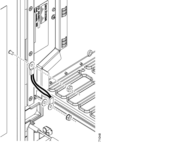
The ONS 15454 door locks with a pinned hex key that ships with the ONS 15454. A button on the right side of the shelf assembly releases the door. You can remove the front door of the ONS 15454 to provide unrestricted access to the front of the shelf assembly. Before you remove the front door, you have to remove the ground strap of the front door ( Figure 1-5).
Figure 1-5 ONS 15454 Front Door Ground Strap
Figure 1-6 shows how to remove the front door.
Figure 1-6 Removing the ONS 15454 Front Door
An erasable label is pasted on the inside of the front door ( Figure 1-7). You can use the label to record slot assignments, port assignments, card types, node ID, rack ID, and serial number for the ONS 15454.
Figure 1-7 Front-Door Erasable Label
Note
Figure 1-8 Laser Warning on the Front-Door Label
1.4 Backplane Covers
If a backplane does not have an EIA panel installed, it should have two sheet metal backplane covers (one on each side of the backplane) as shown in Figure 1-9. Each cover is held in place with nine 6-32 x 3/8 inch Phillips screws.
Note
Figure 1-9 Backplane Covers
1.4.1 Lower Backplane Cover
The lower section of the ONS 15454 backplane is covered by either a clear plastic protector (15454-SA-ANSI) or a sheet metal cover (15454-SA-HD), which is held in place by five 6-32 x 1/2 inch screws. Remove the lower backplane cover to access the alarm interface panel (AIP), alarm pin fields, frame ground, and power terminals ( Figure 1-10).
Figure 1-10 Removing the Lower Backplane Cover
1.4.2 Rear Cover
The ONS 15454 has an optional clear plastic rear cover. This clear plastic cover provides additional protection for the cables and connectors on the backplane. Figure 1-11 shows the rear cover screw locations.
Figure 1-11 Backplane Attachment for Cover
You can also install the optional spacers if more space is needed between the cables and rear cover ( Figure 1-12).
Figure 1-12 Installing the Plastic Rear Cover with Spacers
1.4.3 Alarm Interface Panel
The AIP is located above the alarm contacts on the lower section of the backplane. The AIP provides surge protection for the ONS 15454. It also provides an interface from the backplane to the fan-tray assembly and LCD. The AIP plugs into the backplane using a 96-pin DIN connector and is held in place with two retaining screws. The panel has a nonvolatile memory chip that stores the unique node address (MAC address).
Note
The 5-A AIP (73-7665-XX) is required when installing the new fan-tray assembly (15454-FTA3), which comes preinstalled on the shelf assembly (15454-SA-ANSI or 15454-SA-HD).
Note
1.4.4 Alarm Interface Panel Replacement
If the alarm interface panel (AIP) fails, a MAC Fail alarm appears on the CTC Alarms menu and/or the LCD display on the fan-tray assembly goes blank. To perform an in-service replacement of the AIP, you must contact Cisco Technical Assistance Center (TAC). For contact information, go to the TAC website at http://www.cisco.com/tac.
You can replace the AIP on an in-service system without affecting traffic (except Ethernet traffic on nodes running a software release earlier than Release 4.0). The circuit repair feature allows you to repair circuits affected by MAC address changes on one node at a time. Circuit repair works when all nodes are running the same software version. Each individual AIP upgrade requires an individual circuit repair; if AIPs are replaced on two nodes, the circuit repair must be performed twice.
Caution
Note
1.5 Electrical Interface Assemblies
Optional EIA backplane covers are typically preinstalled when ordered with the ONS 15454. EIAs must be ordered when using DS-1, DS-3, DS3XM, or EC-1 cards. This section describes each EIA.
Six different EIA backplane covers are available for the ONS 15454: BNC, High-Density BNC, MiniBNC, SMB, AMP Champ, UBIC-H (Universal Backplane Interface Connector-Horizontal), and UBIC-V (Vertical). If the shelf was not shipped with the correct EIA interface, you must order and install the correct EIA.
EIAs are attached to the shelf assembly backplane to provide electrical interface cable connections. EIAs are available with SMB and BNC connectors for DS-3 or EC-1 cards. EIAs are available with AMP Champ connectors for DS-1 cards. You must use SMB EIAs for DS-1 twisted-pair cable installation. UBIC-V EIAs have SCSI connectors. They are available for use with any DS-1, DS-3, or EC-1 card, but are intended for use with high-density electrical cards.
Note
You can install EIAs on one or both sides of the ONS 15454 backplane in any combination (in other words, AMP Champ on Side A and BNC on Side B or High-Density BNC on Side A and SMB on Side B, and so forth). As you face the rear of the ONS 15454 shelf assembly, the right side is the A side and the left side is the B side. The top of the EIA connector columns are labeled with the corresponding slot number, and EIA connector pairs are marked transmit (Tx) and receive (Rx) to correspond to transmit and receive cables.
Note
1.5.1 EIA Installation
Optional EIA backplane covers are typically preinstalled when ordered with the ONS 15454. A minimal amount of assembly might be required when EIAs are ordered separately from the ONS 15454. If you are installing EIAs after the shelf assembly is installed, plug the EIA into the backplane. The EIA has six electrical connectors that plug into six corresponding backplane connectors. The EIA backplane must replace the standard sheet metal cover to provide access to the coaxial cable connectors. The EIA sheet metal covers use the same screw holes as the solid backplane panels, but they have 12 additional 6-32 x 1/2 inch Phillips screw holes so you can screw down the cover and the board using standoffs on the EIA board.
When using the RG-179 coaxial cable on an EIA, the maximum distance available (122 feet [37 meters]) is less than the maximum distance available with standard RG-59 (734A) cable (306 feet [93 meters]). The maximum distance when using the RG-59 (734A) cable is 450 feet (137 meters). The shorter maximum distance available with the RG179 is due to a higher attenuation rate for the thinner cable. Attenuation rates are calculated using a DS-3 signal:
•
•
1.5.2 EIA Configurations
Table 1-1 shows the EIA types supported only by ONS 15454 shelf assembly 15454-SA-ANSI.
Table 1-2 shows the EIA types supported by both the 15454-SA-ANSI and the 15454-SA-HD (high density) shelf assemblies.
1.5.3 BNC EIA
The ONS 15454 BNC EIA supports 24 DS-3 circuits on each side of the ONS 15454 (24 transmit and 24 receive connectors). If you install BNC EIAs on both sides of the shelf assembly, the ONS 15454 hosts up to 48 circuits. The BNC connectors on the EIA supports Trompeter UCBJ224 (75-ohm) 4-leg connectors (King or ITT are also compatible). Right-angle mating connectors for the connecting cable are AMP 413588-2 (75-ohm) connectors. If preferred, you can also use a straight connector of the same type. Use RG-59/U cable to connect to the ONS 15454 BNC EIA. These cables are recommended to connect to a patch panel and are designed for long runs. You can use BNC EIAs for DS-3 (including the DS3XM-6 and DS3XM-12) or EC-1 cards.
Figure 1-13 shows the ONS 15454 with preinstalled BNC EIAs.
To install coaxial cable with BNC connectors, refer to the "Install Shelf and Backplane Hardware" chapter in the Cisco ONS 15454 Procedure Guide.
Figure 1-13 BNC Backplane for Use in 1:1 Protection Schemes
1.5.3.1 BNC Connectors
The EIA side marked "A" has 24 pairs of BNC connectors. The first 12 pairs of BNC connectors correspond to Ports 1 to 12 for a 12-port card and map to Slot 2 on the shelf assembly. The BNC connector pairs are marked "Tx" and "Rx" to indicate transmit and receive cables for each port. You can install an additional card in Slot 1 as a protect card for the card in Slot 2. The second 12 BNC connector pairs correspond to Ports 1 to 12 for a 12-port card and map to Slot 4 on the shelf assembly. You can install an additional card in Slot 3 as a protect card for the card in Slot 4. Slots 5 and 6 do not support DS-3 cards when the standard BNC EIA panel connectors are used.
The EIA side marked "B" provides an additional 24 pairs of BNC connectors. The first 12 BNC connector pairs correspond to Ports 1 to 12 for a 12-port card and map to Slot 14 on the shelf assembly. The BNC connector pairs are marked "Tx" and "Rx" to indicate transmit and receive cables for each port. You can install an additional card in Slot 15 as a protect card for the card in Slot 14. The second 12 BNC connector pairs correspond to Ports 1 to 12 for a 12-port card and map to Slot 16 on the shelf assembly. You can install an additional card in Slot 17 as a protect card for the card in Slot 16. Slots 12 and 13 do not support DS-3 cards when the standard BNC EIA panel connectors are used.
When BNC connectors are used with a DS3N-12 card in Slot 3 or 15, the 1:N card protection extends only to the two slots adjacent to the 1:N card due to BNC wiring constraints.
1.5.3.2 BNC Insertion and Removal Tool
Due to the large number of BNC connectors on the high-density BNC EIA, you might require a special tool for inserting and removing BNC EIAs ( Figure 1-14). This tool also helps with ONS 15454 patch panel connections.
Figure 1-14 BNC Insertion and Removal Tool
This tool can be obtained with P/N 227-T1000 from:
Amphenol USA (www.amphenol.com)
One Kennedy Drive
Danbury, CT 06810
Phone: 203 743-9272 Fax: 203 796-2032This tool can be obtained with P/N RT-1L from:
Trompeter Electronics Inc. (www.trompeter.com)
31186 La Baya Drive
Westlake Village, CA 91362-4047
Phone: 800 982-2629 Fax: 818 706-10401.5.4 High-Density BNC EIA
The ONS 15454 high-density BNC EIA supports 48 DS-3 circuits on each side of the ONS 15454 (48 transmit and 48 receive connectors). If you install BNC EIAs on both sides of the unit, the ONS 15454 hosts up to 96 circuits. The high-density BNC EIA supports Trompeter UCBJ224 (75-ohm) 4-leg connectors (King or ITT are also compatible). Use straight connectors on RG-59/U cable to connect to the high-density BNC EIA. Cisco recommends these cables for connection to a patch panel; they are designed for long runs. You can use high-density BNC EIAs for DS-3 (including the DS3XM-6 and DS3XM-12) or EC-1 cards. Figure 1-15 shows the ONS 15454 with preinstalled high-density BNC EIAs.
To install coaxial cable with high-density BNC connectors, refer to the "Install Shelf and Backplane Cable" in the Cisco ONS 15454 Procedure Guide.
Figure 1-15 High-Density BNC Backplane for Use in 1:N Protection Schemes
The EIA side marked "A" hosts 48 pairs of BNC connectors. Each column of connector pairs is numbered and corresponds to the slot of the same number. The first column (12 pairs) of BNC connectors corresponds to Slot 1 on the shelf assembly, the second column to Slot 2, the third column to Slot 4, and the fourth column to Slot 5. The rows of connectors correspond to Ports 1 to 12 of a 12-port card.
The EIA side marked "B" provides an additional 48 pairs of BNC connectors. The first column (12 pairs) of BNC connectors corresponds to Slot 13 on the shelf assembly, the second column to Slot 14, the third column to Slot 16, and the fourth column to Slot 17. The rows of connectors correspond to Ports 1 to 12 of a 12-port card. The BNC connector pairs are marked "Tx" and "Rx" to indicate transmit and receive cables for each port. The High-Density BNC EIA supports both 1:1 and 1:N protection across all slots except Slots 6 and 12.
1.5.5 MiniBNC EIA
The ONS 15454 MiniBNC EIA supports a maximum of 192 transmit and receive DS-3 connections, 96 per side (A and B) through 192 miniBNC connectors on each side. If you install BNC EIAs on both sides of the unit, the ONS 15454 hosts up to 192 circuits. The MiniBNC EIAs are designed to support DS-3 and EC-1 signals.
The MiniBNC EIA supports the following cards:
•
•
•
•
•
•
•
MiniBNCs support available high-density cards in unprotected and 1:N protection (where N < 2) protection groups.
Table 1-3 shows protection groups and their applicable slot assignments.
1.5.5.1 MiniBNC Connectors
You can install MiniBNCs on one or both sides of the ONS 15454. As you face the rear of the ONS 15454 shelf assembly, the right side is the A side (15454-EIA-HDBNC-A96) and the left side is the B side (15454-EIA-HDBNC-B96). The diagrams adjacent to each row of connectors indicate the slots and ports that correspond with each connector in that row, depending on whether you are using a high density (HD) or low density (LD) configuration. The MiniBNC connector pairs are marked Tx and Rx to indicate transmit and receive cables for each port.
Figure 1-16 shows the ONS 15454 with preinstalled MiniBNC EIAs.
To install coaxial cable with MiniBNC connectors, refer to the "Install the Shelf and Backplane Cable" chapter in the Cisco ONS 15454 Procedure Guide.
Figure 1-16 MiniBNC Backplane for Use in 1:N Protection Schemes
Table 1-4 and Table 1-5 show the J-labeling and corresponding card ports for a shelf assembly configured with low-density electrical cards.
Table 1-6 and Table 1-7 show the J-labeling and corresponding card ports for a shelf assembly configured with high-density 48-port DS-3/EC-1electrical cards.
1.5.5.2 MiniBNC Insertion and Removal Tool
Due to the large number of MiniBNC connectors on the MiniBNC EIA, you might require a special tool for inserting and removing MiniBNC EIAs ( Figure 1-17). This tool also helps with ONS 15454 patch panel connections.
Figure 1-17 MiniBNC Insertion and Removal Tool
This tool can be obtained with P/N 227-T1000 from:
Amphenol USA (www.amphenol.com)
One Kennedy Drive
Danbury, CT 06810
Phone: 203 743-9272 Fax: 203 796-2032This tool can be obtained with P/N RT-1L from:
Trompeter Electronics Inc. (www.trompeter.com)
31186 La Baya Drive
Westlake Village, CA 91362-4047
Phone: 800 982-2629 Fax: 818 706-10401.5.6 SMB EIA
The ONS 15454 SMB EIA supports AMP 415484-1 75-ohm 4-leg connectors. Right-angle mating connectors for the connecting cable are AMP 415484-2 (75-ohm) connectors. Use RG-179/U cable to connect to the ONS 15454 EIA. Cisco recommends these cables for connection to a patch panel; they are not designed for long runs. Range does not affect loopback testing.
You can use SMB EIAs with DS-1, DS-3 (including the DS3XM-6 and DS3XM-12), and EC-1 cards. If you use DS-1 cards, use the DS-1 electrical interface adapter (balun) to terminate the twisted pair DS-1 cable to the SMB EIA (see the "Electrical Interface Adapters" section). SMB EIAs support 14 ports per slot when used with a DS-1 card, 12 ports per slot when used with a DS-3 or EC-1 card, and 6 ports per slot when used with a DS3XM-6 card.
Figure 1-18 shows the ONS 15454 with preinstalled SMB EIAs and the sheet metal cover and screw locations for the EIA. The SMB connectors on the EIA are AMP 415504-3 (75-ohm) 4-leg connectors.
To install SMB connectors, refer to the "Install Shelf and Backplane Cable" chapter in the Cisco ONS 15454 Procedure Guide.
Figure 1-18 SMB EIA Backplane
The SMB EIA has 84 transmit and 84 receive connectors on each side of the ONS 15454 for a total of 168 SMB connectors (84 circuits).
The EIA side marked "A" hosts 84 SMB connectors in six columns of 14 connectors. The "A" side columns are numbered 1 to 6 and correspond to Slots 1 to 6 on the shelf assembly. The EIA side marked "B" hosts an additional 84 SMB connectors in six columns of 14 connectors. The "B" side columns are numbered 12 to 17 and correspond to Slots 12 to 17 on the shelf assembly. The connector rows are numbered 1 to 14 and correspond to the 14 ports on a DS-1 card.
For DS-3 or EC-1 cards, the EIA supports 72 transmit and 72 receive connectors, for a total of 144 SMB connectors (72 circuits). If you use a DS-3 or EC-1 card, only Ports 1 to 12 are active. If you use a DS3XM-6 card, only Ports 1 to 6 are active. The SMB connector pairs are marked "Tx" and "Rx" to identify transmit and receive cables for each port. If you use SMB connectors, you can install DS-1, DS-3, or EC-1 cards in Slots 1 to 4 or 14 to 17.
1.5.7 AMP Champ EIA
The ONS 15454 AMP Champ EIA supports 64-pin (32 pair) AMP Champ connectors for each slot on both sides of the shelf assembly where the EIA is installed. Cisco AMP Champ connectors are female AMP # 552246-1 with AMP # 552562-2 bail locks. Each AMP Champ connector supports 14 DS-1 ports. You can use AMP Champ EIAs with DS-1 cards only. Figure 1-19 shows the ONS 15454 with preinstalled AMP Champ EIAs and the corresponding sheet metal cover and screw locations for the EIA.
To install AMP Champ connector DS-1 cables, you must use 64-pin bundled cable connectors with a 64-pin male AMP Champ connector. You need an AMP Champ connector #552276-1 for the receptacle side and #1-552496-1 (for cable diameter 0.475 in. to 0.540 in.) or #2-552496-1 (for cable diameter 0.540 in. to 0.605 in.) for the right-angle shell housing (or their functional equivalent). The corresponding 64-pin female AMP Champ connector on the AMP Champ EIA supports one receive and one transmit for each DS-1 port for the corresponding card slot.
Because each DS1-14 card supports 14 DS-1 ports, only 56 pins (28 pairs) of the 64-pin connector are used. Prepare one 56-wire cable for each DS-1 facility installed.
Figure 1-19 AMP Champ EIA Backplane
Table 1-8 shows the pin assignments for the AMP Champ connectors on the ONS 15454 AMP Champ EIA. The EIA side marked "A" hosts six AMP Champ connectors. The connectors are numbered 1 to 6 for the corresponding slots on the shelf assembly. Each AMP Champ connector on the backplane supports 14 DS-1 ports for a DS1-14 card, and each connector features 28 live pairs—one transmit pair and one receive pair—for each DS-1 port.
The EIA side marked "B" hosts six AMP Champ connectors. The connectors are labeled 12 to 17 for the corresponding slots on the shelf assembly. Each AMP Champ connector on the backplane supports 14 DS-1 ports for a DS1-14 card, and each connector features 28 live pairs—one transmit pair and one receive pair—for each DS-1 port.
Note
Caution
Table 1-9 shows the pin assignments for the AMP Champ connectors on the ONS 15454 AMP Champ EIA for a shielded DS-1 cable.
When using DS-1 AMP Champ cables, you must equip the ONS 15454 with an AMP Champ connector EIA on each side of the backplane where DS-1 cables will terminate. Each AMP Champ connector on the EIA corresponds to a slot in the shelf assembly and is numbered accordingly. The AMP Champ connectors have screw-down tooling at each end of the connector.
1.5.8 UBIC-V EIA
UBIC-V EIAs are attached to the shelf assembly backplane to provide up to 112 transmit and receive connections through 16 SCSI connectors per side (A and B). The UBIC-V EIAs are designed to support DS-1, DS-3, and EC-1 signals. The appropriate cable assembly is required depending on the type of signal.
You can install UBIC-Vs on one or both sides of the ONS 15454. As you face the rear of the ONS 15454 shelf assembly, the right side is the A side (15454-EIA-UBICV-A) and the left side is the B side (15454-EIA-UBICV-B). The diagrams adjacent to each row of SCSI connectors indicate the slots and ports that correspond with each SCSI connector in that row, depending on whether you are using a high-density (HD) or low-density (LD) configuration.
UBIC-V EIAs will support high-density electrical cards (DS3/EC1-48, DS1/E1-56), as well as low-density electrical cards.
Figure 1-20 shows the A- and B-side slot assignments.
Figure 1-20 UBIC-V Slot Designations
The UBIC-V sheet metal covers use the same screw holes as the standard sheet metal covers, but they have 12 additional holes for pan-head screws and three holes for jack screws, so you can screw down the cover and the board using standoffs on the UBIC-V board.
When installed with the standard door and cabling on the backplane, the ONS 15454 shelf measures approximately 15.7 inches (399 mm) deep when partially populated with backplane cables, 16.1 inches (409 mm) deep when fully populated, and 16.75 inches (425 mm) deep with the rear cover installed. When installed with the deep door and cabling on the backplane, the ONS 15454 shelf measures approximately 17.5 inches (445 mm) deep when partially populated with backplane cables, 17.9 inches (455 mm) deep when fully populated, and 18.55 inches (471 mm) deep with the rear cover installed.
The UBIC-V EIA supports the following cards:
•
•
•
•
•
•
•
•
•
The A and B sides each host 16 high-density, 50-pin SCSI connectors. The A-side maps to Slots 1 through 6 and the B-side maps to Slots 12 through 17.
In Software Releases 4.1.x and 4.6, UBIC-Vs support unprotected, 1:1, and 1:N (N < 5) protection groups. In Software R5.0 and later, UBIC-Vs also support available high-density cards in unprotected and 1:N (N < 2) protection groups.
Table 1-10 shows the UBIC-V protection types and their applicable slot assignments.
1.5.9 UBIC-H EIA
UBIC-H EIAs are attached to the shelf assembly backplane to provide up to 112 transmit and receive DS-1 connections through 16 SCSI connectors per side (A and B) or 96 transmit and receive DS-3 connections. The UBIC-H EIAs are designed to support DS-1, DS-3, and EC-1 signals. The appropriate cable assembly is required depending on the type of signal.
You can install UBIC-Hs on one or both sides of the ONS 15454. As you face the rear of the ONS 15454 shelf assembly, the right side is the A side (15454-EIA-UBICH-A) and the left side is the B side (15454-EIA-UBICH-B). The diagrams adjacent to each row of SCSI connectors indicate the slots and ports that correspond with each SCSI connector in that row, depending on whether you are using a high density (HD) or low density (LD) configuration.
Note
Figure 1-21 shows the A- and B-side connector labeling.
Figure 1-21 UBIC-H EIA Connector Labeling
Tables 1-11 and 1-12 show the J-labeling and corresponding card ports for a shelf assembly configured with low-density electrical cards.
Tables 1-13 and 1-14 show the J-labeling and corresponding card ports for a shelf assembly configured with high-density 48-port DS-3/EC-1 or 56-port DS-1 electrical cards.
If you are installing UBIC-H EIAs after the shelf assembly is installed, plug the UBIC-H EIA into the backplane. The UBIC-H backplane must replace the standard sheet metal cover to provide access to the cable connectors. The UBIC-H sheet metal covers use the same screw holes as the standard sheet metal covers, but they have 12 additional holes for panhead screws and three holes for jack screws so you can screw down the cover and the board using standoffs on the UBIC-H board.
When installed with the standard door and cabling on the backplane, the ONS 15454 shelf measures approximately 14.5 inches deep when fully populated with backplane cables, and 15.0 inches deep with the rear cover installed. When installed with the deep door and cabling on the backplane, the ONS 15454 shelf measures approximately 16.5 inches deep when fully populated with backplane cables, and 17.0 inches deep with the rear cover installed.
The UBIC-H EIA supports the following cards:
•
•
•
•
•
•
•
•
The A and B sides each host 16 high-density, 50-pin SCSI connectors. The A-side maps to Slots 1 through 6 and the B-side maps to Slots 12 through 17.
In Software Releases prior to Release 5.0, UBIC-Hs support unprotected, 1:1, and 1:N (where N < 5) protection groups. In Software R5.0 and greater, UBIC-Hs additionally support available high-density cards in unprotected and 1:N protection (where N < 2) protection groups.
Table 1-15 shows protection groups and their applicable slot assignments.
1.5.10 EIA Replacement
Before you attach a new EIA, you must remove the backplane cover or EIA already installed on the ONS 15454. Refer to the spare document(s) for the EIA type(s) you are removing and replacing for specific information.
1.6 Coaxial Cable
Caution
When using ONS 15454 DS-3 electrical cables, the cables must terminate on an EIA installed on the ONS 15454 backplane. All DS-3 cables connected to the ONS 15454 DS-3 card must terminate with coaxial cables using the desired connector type to connect to the specified EIA.
The electromagnetic compatibility (EMC) performance of the node depends on good-quality DS-3 coaxial cables, such as Shuner Type G 03233 D, or the equivalent.
1.7 DS-1 Cable
DS-1 cables support AMP Champ connectors and twisted-pair wire-wrap cabling. Twisted-pair wire-wrap cables require SMB EIAs.
1.7.1 Twisted Pair Wire-Wrap Cables
Installing twisted-pair, wire-wrap DS-1 cables requires separate pairs of grounded twisted-pair cables for receive (in) and transmit (out). Prepare four cables, two for receive and two for transmit, for each DS-1 facility to be installed.
Caution
If you use DS-1 electrical twisted-pair cables, equip the ONS 15454 with an SMB EIA on each side of the backplane where DS-1 cables will terminate. You must install special DS-1 electrical interface adapters, commonly referred to as a balun, on every transmit and receive connector for each DS-1 termination.
1.7.2 Electrical Interface Adapters
Note
If you install DS-1 cards in the ONS 15454, you must fit the corresponding transmit and receive SMB connectors on the EIA with a DS-1 electrical interface adapter. You can install the adapter on the SMB connector for the port. The adapter has wire-wrap posts for DS-1 transmit and receive cables. Figure 1-22 shows the DS-1 electrical interface adapter.
Note
Figure 1-22 DS-1 Electrical Interface Adapter (Balun)
Each DS-1 electrical interface adapter has a female SMB connector on one end and a pair of 0.045 inch (1.14 mm) square wire-wrap posts on the other end. The wire-wrap posts are 0.200 inches (5.08 mm) apart.
Caution
1.8 UBIC-V Cables
When using the DS-1 cables on a UBIC-V, the maximum distance is 655 feet (199.6 m). When using the RG-59 (734A) DS-3/EC-1 cables on a UBIC-V, the maximum distance is 450 feet (137.2 m). The maximum distance when using the RG179 DS-3/EC-1 cable (79 feet [24.1 m]) is due to a higher attenuation rate for the thinner cable. Attenuation rates are calculated using a DS-3 signal:
•
•
The following cables are available for use with the UBIC-V EIA:
•
•
•
•
•
•
Figure 1-23 shows the pin locations on the DS-1 and DS-3/EC-1 SCSI connectors.
Figure 1-23 Cable Connector Pins
Table 1-16 shows the UBIC-V SCSI connector pin assignments for the DS-1 and DS-3/EC-1 cables.
Table 1-17 shows the UBIC-V EIA DS-1 cable wiring.
1.9 UBIC-H Cables
The UBIC-H EIA is designed to support DS-1, DS-3, or EC-1 signals. The type of signal supported is determined by the UBIC-H cable assembly selected. To support DS-1 signals, select the DS-1 UBIC-H cable assembly (part number 15454-CADS1-H-<length>). For DS-3 or EC-1 signals, select the DS-3/EC-1 UBIC-H cable assembly (part number 15454-CADS3-H-<length>).
DS-1 cables for the UBIC-H have a maximum supported distance of 655 feet. The following DS-1 cables are available from Cisco Systems for use with the UBIC-H EIA:
•
•
•
•
•
•
•
•
•
DS-3/EC-1 cables for the UBIC-H have a maximum supported distance of 450 feet. The following DS-3/EC-1 cables are available from Cisco Systems for use with the UBIC-H EIA:
•
•
•
•
•
•
•
•
•
•
•
Figure 1-24 shows the pin locations on the DS-1 and DS-3/EC-1 SCSI connectors.
Figure 1-24 Cable Connector Pins
Table 1-18 shows the UBIC-H SCSI connector pin assignments for the DS-1 and DS-3/EC-1 cables.
Table 1-19 shows the UBIC-H EIA DS-1 cable wiring.
1.10 Ethernet Cables
Ethernet cables use RJ-45 connectors, and are straight-through or crossover, depending on what is connected to them.
Table 1-20 shows 100Base-TX connector pin assignments, used with E100 Ethernet cards in the ONS 15454.
Figure 1-25 shows the pin locations on 100BaseT connector.
Figure 1-25 100BaseT Connector Pins
Figure 1-26 shows the straight-through Ethernet cable schematic. Use a straight-through cable when connecting to a router or a PC.
Figure 1-26 Straight-Through Cable
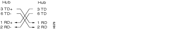
Figure 1-27 shows the crossover Ethernet cable schematic. Use a crossover cable when connecting to a switch or hub.
Figure 1-27 Crossover Cable
1.11 Cable Routing and Management
The ONS 15454 cable management facilities include the following:
•
•
Note
•
•
•
•
Note
•
Figure 1-28 shows the cable management facilities that you can access through the fold-down front door, including the cable-routing channel and cable-routing channel posts.
Figure 1-28 Managing Cables on the Front Panel
1.11.1 Fiber Management
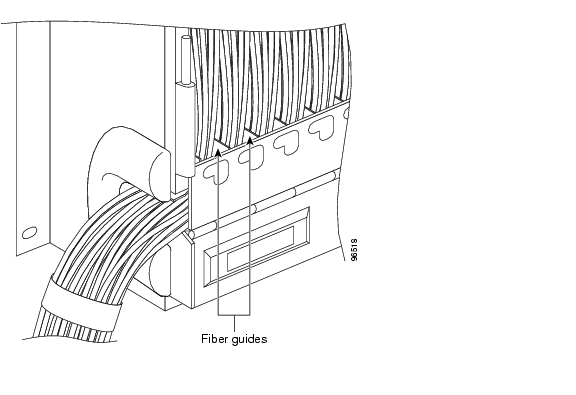
The jumper routing fins are designed to route fiber jumpers out of both sides of the shelf. Slots 1 to 6 exit to the left, and Slots 12 to 17 exit to the right. Figure 1-29 shows fibers routed from cards in the left slots, down through the fins, then exiting out the fiber channel to the left. The maximum capacity of the fiber routing channel depends on the size of the fiber jumpers. Table 1-21 gives the maximum capacity of the fiber channel for each side of the shelf, for the different fiber sizes.
Figure 1-29 Fiber Capacity
Table 1-21 provides the maximum capacity of the fiber channel for one side of a shelf, depending on fiber size and number of Ethernet cables running through that fiber channel.
Plan your fiber size according to the number of cards/ports installed in each side of the shelf. For example, if your port combination requires 36 fibers, 3 mm (0.11 inch) fiber is adequate. If your port combination requires 68 fibers, you must use 2 mm(0.7 inch) or smaller fibers.
1.11.2 Fiber Management Using the Tie-Down Bar
You can install an optional 5-inch (127 mm) tie-down bar on the rear of the ANSI chassis. You can use tie-wraps or other site-specific material to bundle the cabling and attach it to the bar so that you can more easily route the cable away from the rack.
Figure 1-30 shows the tie-down bar, the ONS 15454, and the rack.
Figure 1-30 Tie-Down Bar
1.11.3 Coaxial Cable Management
Coaxial cables connect to EIAs on the ONS 15454 backplane using cable connectors. EIAs feature cable-management eyelets for tie wrapping or lacing cables to the cover panel.
1.11.4 DS-1 Twisted-Pair Cable Management
Connect twisted pair/DS-1 cables to SMB EIAs on the ONS 15454 backplane using cable connectors and DS-1 EIAs (baluns).
1.11.5 AMP Champ Cable Management
EIAs have cable management eyelets to tiewrap or lace cables to the cover panel. Tie wrap or lace the AMP Champ cables according to local site practice and route the cables. If you configure the ONS 15454 for a 23-inch (584.2 mm) rack, two additional inches (50.8 mm) of cable management area is available on each side of the shelf assembly.
1.12 Alarm Expansion Panel
The optional ONS 15454 alarm expansion panel (AEP) can be used with the Alarm Interface Controller—International card (AIC-I) card to provide an additional 48 dry alarm contacts for the ONS 15454, 32 of which are inputs and 16 are outputs. The AEP is a printed circuit board assembly that is installed on the backplane. Figure 1-31 shows the AEP board; the left connector is the input connector and the right connector is the output connector.
The AIC-I without an AEP already contains direct alarm contacts. These direct AIC-I alarm contacts are routed through the backplane to wire-wrap pins accessible from the back of the shelf. If you install an AEP, you cannot use the alarm contacts on the wire-wrap pins. For further information about the AIC-I, see the "2.7 AIC-I Card" section on page 2-26.
Figure 1-31 AEP Printed Circuit Board Assembly
Figure 1-32 shows the AEP block diagram.
Figure 1-32 AEP Block Diagram
Each AEP alarm input port has provisionable label and severity. The alarm inputs have optocoupler isolation. They have one common 48-VDC output and a maximum of 2 mA per input. Each opto metal oxide semiconductor (MOS) alarm output can operate by definable alarm condition, a maximum open circuit voltage of 60 VDC, anda maximum current of 100 mA. See the "2.7.2 External Alarms and Controls" section on page 2-28 for further information.
1.12.1 Wire-Wrap and Pin Connections
Figure 1-33 shows the wire-wrapping connections on the backplane.
Figure 1-33 AEP Wire-Wrap Connections to Backplane Pins
Table 1-22 shows the backplane pin assignments and corresponding signals on the AIC-I and AEP.
Figure 1-34 is a circuit diagram of the alarm inputs (Inputs 1 and 32 are shown in the example).
Figure 1-34 Alarm Input Circuit Diagram
Table 1-23 lists the connections to the external alarm sources.
Figure 1-35 is a circuit diagram of the alarm outputs (Outputs 1 and 16 are shown in the example).
Figure 1-35 Alarm Output Circuit Diagram
Use the pin numbers in Table 1-24 to connect to the external elements being switched by external alarms.
1.13 Filler Card
Filler cards are designed to occupy empty multiservice and AIC-I slots in the Cisco ONS 15454 (Slots 1-6, 9, and 12 - 17). The filler card cannot operate in the XC slots (Slots 8 and 10) or TCC slots (7 and 11). When installed, the filler card aids in maintaining proper air flow and EMI requirements.
Note
Figure 1-36 shows the faceplate of the detectable filler card. The filler cards have no card-level LED indicators.
Figure 1-36 Detectable Filler Card Faceplate
1.14 Fan-Tray Assembly
The fan-tray assembly is located at the bottom of the ONS 15454 bay assembly. The fan tray is a removable drawer that holds fans and fan-control circuitry for the ONS 15454. The front door can be left in place or removed before installing the fan-tray assembly. After you install the fan tray, you should only need to access it if a fan failure occurs or if you need to replace or clean the fan-tray air filter.
The front of the fan-tray assembly has an LCD screen that provides slot- and port-level information for all ONS 15454 card slots, including the number of Critical, Major, and Minor alarms. For optical cards, you can use the LCD to determine if a port is in working or protect mode and is active or standby. The LCD also tells you whether the software load is SONET or SDH and the software version number.
Note
Caution
Note
1.14.1 Fan Speed and Power Requirements
Fan speed is controlled by TCC2/TCC2P card temperature sensors. The sensors measure the input air temperature at the fan-tray assembly. Fan speed options are low, medium, and high. If the TCC2/TCC2P card fails, the fans automatically shift to high speed. The temperature measured by the TCC/TCC2P2 sensors is displayed on the LCD screen.
Table 1-25 lists power requirements for the fan-tray assembly.
Table 1-25 Fan Tray Assembly Power Requirements
53
1.21
198
86.4
1.8
295
1.14.2 Fan Failure
If one or more fans fail on the fan-tray assembly, replace the entire assembly. You cannot replace individual fans. The red Fan Fail LED on the front of the fan tray illuminates when one or more fans fail. For fan tray replacement instructions, refer to the Cisco ONS 15454 Troubleshooting Guide. The red Fan Fail LED clears after you install a working fan tray.
1.14.3 Air Filter
The ONS 15454 contains a reusable air filter; Model 15454-FTF2, that is installed either beneath the fan-tray assembly or in the optional external filter brackets. Earlier versions of the ONS 15454 used a disposable air filter that is installed beneath the fan-tray assembly only. However, the reusable air filter is backward compatible.
The reusable filter is made of a gray, open-cell, polyurethane foam that is specially coated to provide fire and fungi resistance. All versions of the ONS 15454 can use the reusable air filter. Spare filters should be kept in stock.
Caution
Caution
1.15 Power and Ground Description
Ground the equipment according to Telcordia standards or local practices.
Cisco recommends the following wiring conventions, but customer conventions prevail:
•
•
•
The ONS 15454 has redundant -48 VDC #8 power terminals on the shelf-assembly backplane. The terminals are labeled BAT1, RET1, BAT2, and RET2 and are located on the lower section of the backplane behind a clear plastic cover.
To install redundant power feeds, use four power cables and one ground cable. For a single power feed, only two power cables (#10 AWG, 2.588 mm≤ [0.1018 inch], copper conductor, 194ΑF [90ΑC]) and one ground cable (#6 AWG, 4.115 mm≤ [0.162 inch]) are required. Use a conductor with low impedance to ensure circuit overcurrent protection. However, the conductor must have the capability to safely conduct any faulty current that might be imposed.
Note
The existing ground post is a #10-32 bolt. The nut provided for a field connection is also a #10 AWG (2.588 mm≤ [0.1018 inch]), with an integral lock washer. The lug must be a dual-hole type and rated to accept the #6 AWG (4.115 mm≤ [0.162 inch]) cable. Two posts are provided on the Cisco ONS 15454 to accommodate the dual-hole lug. Figure 1-37 shows the location of the ground posts.
Figure 1-37 Ground Posts on the ONS 15454 Backplane
1.16 Alarm, Timing, LAN, and Craft Pin Connections
Caution
The ONS 15454 has a backplane pin field located at the bottom of the backplane. The backplane pin field provides 0.045 square inch (29 mm2) wire-wrap pins for enabling external alarms, timing input and output, and craft interface terminals. This section describes the backplane pin field and the pin assignments for the field. Figure 1-38 shows the wire-wrap pins on the backplane pin field. Beneath each wire-wrap pin is a frame ground pin. Frame ground pins are labeled FG1, FG2, FG3, etc. Install the ground shield of the cables connected to the backplane to the ground pin that corresponds to the pin field used.
Note
Figure 1-38 ONS 15454 Backplane Pinouts (Release 3.4 or Later)
Figure 1-39 ONS 15454 Backplane Pinouts
1.16.1 Alarm Contact Connections
The alarm pin field supports up to 17 alarm contacts, including four audible alarms, four visual alarms, one alarm cutoff (ACO), and four user-definable alarm input and output contacts.
Audible alarm contacts are in the LOCAL ALARM AUD pin field and visual contacts are in the LOCAL ALARM VIS pin field. Both of these alarms are in the LOCAL ALARMS category. User-definable contacts are in the ENVIR ALARM IN (external alarm) and ENVIR ALARM OUT (external control) pin fields. These alarms are in the ENVIR ALARMS category; you must have the AIC-I card installed to use the ENVIR ALARMS. Alarm contacts are Normally Open (N/O), meaning that the system closes the alarm contacts when the corresponding alarm conditions are present. Each alarm contact consists of two wire-wrap pins on the shelf assembly backplane. Visual and audible alarm contacts are classified as critical, major, minor, and remote. Figure 1-39 shows alarm pin assignments.
Visual and audible alarms are typically wired to trigger an alarm light or bell at a central alarm collection point when the corresponding contacts are closed. You can use the Alarm Cutoff pins to activate a remote ACO for audible alarms. You can also activate the ACO function by pressing the ACO button on the TCC2/TCC2P card faceplate. The ACO function clears all audible alarm indications. After clearing the audible alarm indication, the alarm is still present and viewable in the Alarms tab in CTC. For more information, see the "2.7.2 External Alarms and Controls" section on page 2-28.
1.16.2 Timing Connections
The ONS 15454 backplane supports two building integrated timing supply (BITS) clock pin fields. The first four BITS pins, rows 3 and 4, support output and input from the first external timing device. The last four BITS pins, rows 1 and 2, perform the identical functions for the second external timing device. Table 1-26 lists the pin assignments for the BITS timing pin fields.
Note
Note
For more information, see Chapter 10, "Timing."
1.16.3 LAN Connections
Use the LAN pins on the ONS 15454 backplane to connect the ONS 15454 to a workstation or Ethernet LAN, or to a LAN modem for remote access to the node. You can also use the LAN port on the TCC2/TCC2P card faceplate to connect a workstation or to connect the ONS 15454 to the network. Table 1-27 shows the LAN pin assignments.
Before you can connect an ONS 15454 to other ONS 15454s or to a LAN, you must change the default IP address that is shipped with each ONS 15454 (192.1.0.2).
Table 1-27 LAN Pin Assignments
LAN 1
Connecting to data circuit-terminating equipment (DCE1 , a hub or switch)B2
1
A2
2
B1
3
A1
6
LAN 1
Connecting to data terminal equipment (DTE) (a PC/workstation or router)B1
1
A1
2
B2
3
A2
6
1 The Cisco ONS 15454 is DCE.
1.16.4 TL1 Craft Interface Installation
You can use the craft pins on the ONS 15454 backplane or the EIA/TIA-232 port on the TCC2/TCC2P card faceplate to create a VT100 emulation window to serve as a TL1 craft interface to the ONS 15454. Use a straight-through cable to connect to the EIA/TIA-232 port. Table 1-28 shows the pin assignments for the CRAFT pin field.
Note
Note
Table 1-28 Craft Interface Pin Assignments
Craft
A1
Receive
A2
Transmit
A3
Ground
A4
DTR
1.17 Cards and Slots
ONS 15454 cards have electrical plugs at the back that plug into electrical connectors on the shelf- assembly backplane. When the ejectors are fully closed, the card plugs into the assembly backplane. Figure 1-40 shows card installation.
Figure 1-40 Installing Cards in the ONS 15454
1.17.1 Card Slot Requirements
The ONS 15454 shelf assembly has 17 card slots numbered sequentially from left to right. Slots 1 to 6 and 12 to 17 are multiservice slots that are used for electrical, optical, and Ethernet cards (traffic cards). Card compatibility depends on the EIA, protection scheme, and cross-connect card type used in the shelf. Refer to the "3.1.2 Card Compatibility" section on page 3-3 for more detailed compatibility information.
Slots 7 and 11 are dedicated to TCC2/TCC2P cards. Slots 8 and 10 are dedicated to cross-connect (XCVT, XC10G, and XC-VXC-10G) cards. Slot 9 is reserved for the optional AIC-I card. Slots 3 and 15 can also host electrical cards that are used for 1:N protection. (See the "7.1 Electrical Card Protection" section on page 7-1 for a list of electrical cards that can operate as protect cards.)
Caution
Shelf assembly slots have symbols indicating the type of cards that you can install in them. Each ONS 15454 card has a corresponding symbol. The symbol on the card must match the symbol on the slot.
Table 1-29 shows the slot and card symbol definitions.
Note
Table 1-30 lists the number of ports, line rates, connector options, and connector locations for ONS 15454 optical and electrical cards.
Table 1-30 Card Ports, Line Rates, and Connectors
DS1-14
14
1.544 Mbps
SMB w/wire wrap adapter, AMP Champ connector
Backplane
DS1N-14
14
1.544 Mbps
SMB w/wire wrap1 adapter, AMP Champ connector
—
DS1/E1-56
56
1.544 Mbps
SMB w/wire wrap2 adapter, AMP Champ connector
—
DS3-12
12
44.736 Mbps
SMB or BNC1
Backplane
DS3N-12
12
44.736 Mbps
SMB or BNC1
—
DS3-12E
12
44.736 Mbps
SMB or BNC1
Backplane
DS3N-12E
12
44.736 Mbps
SMB or BNC1
—
DS3XM-6
6
44.736 Mbps
SMB or BNC1
Backplane
DS3XM-12
12
89.472 Mbps
SMB or BNC1
Backplane
DS3/EC1-48
48
2.147 Gbps
SMB or BNC
Backplane
EC1-12
12
51.84 Mbps
SMB or BNC1
Backplane
E100T-12
12
100 Mbps
RJ-45
Faceplate
E1000-2
2
1 Gbps
SC (GBIC)
Faceplate
E100T-G
12
100 Mbps
RJ-45
Faceplate
E1000-2-G
2
1 Gbps
SC (GBIC)
Faceplate
G1K-4
4
1 Gbps
SC (GBIC)
Faceplate
ML100T-12
12
100 Mbps
RJ-45
Faceplate
ML100X-8
8
100 Mbps
SC (SFP)
Faceplate
CE-100T-8
8
100 Mbps
RJ-45
Faceplate
ML1000-2
2
1 Gbps
LC (SFP)
Faceplate
OC-3 IR
4
155.52 Mbps (STS-3)
SC
Faceplate
OC3 IR/STM4 SH 1310-8
8
155.52 Mbps (STS-3)
LC
Faceplate
OC-12/STM4-4 (IR/LR)
4
622.08 Mbps (STS-12)
SC
Faceplate
OC-12 (IR/LR)
1
622.08 Mbps (STS-12)
SC
Faceplate
OC-48 (IR/LR/ELR)
1
2488.32 Mbps (STS-48)
SC
Faceplate
OC-48 AS (IR/LR)
1
2488.32 Mbps (STS-48)
SC
Faceplate
OC-48 ELR (100GHz, 200GHz)
1
2488.32 Mbps (STS-48)
SC
Faceplate
OC192 SR/STM64 IO 1310
1
9.95 Gbps (STS-192)
SC
Faceplate
OC192 IR/STM64 SH 1550
1
9.95 Gbps (STS-192)
SC
Faceplate
OC192 LR/STM64 LH 1550
1
9.95 Gbps (STS-192)
SC
Faceplate
OC192 LR/STM64 LH ITU 15xx.xx
1
9.95 Gbps (STS-192)
SC
Faceplate
FC_MR-4
4 (only 2 available in R4.6)
1.0625 Gbps
SC
Faceplate
15454_MRC-12
12
Up to 2488.32 Mbps (STM-16), depending on SFP
LC
Faceplate
OC192SR1/STM64IO Short Reach/ OC192/STM64
Any Reach31
9.95 Gbps (STM-64)
LC
Faceplate
1 When used as a protect card, the card does not have a physical external connection. The protect card connects to the working card(s) through the backplane and becomes active when the working card fails. The protect card then uses the physical connection of the failed card.
2 When used as a protect card, the card does not have a physical external connection. The protect card connects to the working card(s) through the backplane and becomes active when the working card fails. The protect card then uses the physical connection of the failed card.
3 These cards are designated as OC192-XFP in CTC.
1.17.2 Card Replacement
To replace an ONS 15454 card with another card of the same type, you do not need to make any changes to the database; remove the old card and replace it with a new card. To replace a card with a card of a different type, physically remove the card and replace it with the new card, then delete the original card from CTC. For specifics, refer to the "Install Cards and Fiber-Optic Cable" chapter in the Cisco ONS 15454 Procedure Guide.
Caution
Note
Note
1.17.3 Ferrites
Place third-party ferrites on certain cables to dampen electromagnetic interference (EMI) from the ONS 15454. Ferrites must be added to meet the requirements of Telcordia GR-1089-CORE. Refer to the ferrite manufacturer documentation for proper use and installation of the ferrites. Ferrite placements on the ONS 15454 can include power cables, AMP Champ connectors, baluns, BNC/SMB connectors, and the wire-wrap pin field.
1.18 Software and Hardware Compatibility
Table 1-31 shows ONS 15454 software and hardware compatibility for nodes configured with XC or XCVT cards for Releases 4.6, 5.0, 6.0, 7.0, and 7.2.
Release 4.7 is a MSTP (Multi Service Transport Platform) release, hence SONET/SDH cards are not supported.
For software compatibility for a specific card, refer to the following URL:
http://cisco.com/en/US/products/hw/optical/ps2006/prod_eol_notices_list.html
Note
Table 1-31 ONS 15454 Software and Hardware Compatibility—XC1 and XCVT Configurations
(7.2)XC2
Fully compatible
Partially supported
Partially supported
Partially supported
Partially supported
XCVT
Fully compatible
Fully compatible
Fully compatible
Fully compatible
Fully compatible
TCC
Not supported
Not supported
Not supported
Not supported
Not supported
TCC+
Not supported
Not supported
Not supported
Not supported
Not supported
TCC2
Fully compatible
Fully compatible
Fully compatible
Fully compatible
Fully compatible
TCC2P
Fully compatible
Fully compatible
Fully compatible
Fully compatible
Fully compatible
AIC
Fully compatible
Fully compatible
Not supported
Not supported
Not supported
AIC-I
Fully compatible
Fully compatible
Fully compatible
Fully compatible
Fully compatible
DS1-14
Fully compatible
Fully compatible
Fully compatible
Fully compatible
Fully compatible
DS1N-14
Fully compatible
Fully compatible
Fully compatible
Fully compatible
Fully compatible
DS1/E1-56
Fully compatible
Fully compatible
Fully compatible
Fully compatible
Fully compatible
DS3-12
Fully compatible
Fully compatible
Partially supported
Partially supported
Partially supported
DS3N-12
Fully compatible
Fully compatible
Partially supported
Partially supported
Partially supported
DS3-12E
Fully compatible
Fully compatible
Fully compatible
Fully compatible
Fully compatible
DS3N-12E
Fully compatible
Fully compatible
Fully compatible
Fully compatible
Fully compatible
DS3XM-6
Fully compatible
Fully compatible
Fully compatible
Fully compatible
Fully compatible
DS3XM-12
Not supported
Fully compatible
Fully compatible
Fully compatible
Fully compatible
EC1-12
Fully compatible
Fully compatible
Fully compatible
Fully compatible
Fully compatible
E100T-12
Fully compatible
Fully compatible
Fully compatible
Fully compatible
Fully compatible
E1000-2
Fully compatible
Fully compatible
Fully compatible
Fully compatible
Fully compatible
E100T- G
Fully compatible
Fully compatible
Fully compatible
Fully compatible
Fully compatible
E1000-2-G
Fully compatible
Fully compatible
Fully compatible
Fully compatible
Fully compatible
G1000-4
Supported in Slots
5 & 6
Fully compatible
Partially supported
Partially supported
Partially supported
G1K-4
Supported in Slots 5, 6, 12, 13
Supported in Slots 5, 6, 12, 13
Supported in Slots 5, 6, 12, 13
Supported in Slots 5, 6, 12, 13
Supported in Slots 5, 6, 12, 13
ML100T-12
Supported in Slots 5, 6, 12, 13
Supported in Slots 5, 6, 12, 13
Supported in Slots 5, 6, 12, 13
Supported in Slots 5, 6, 12, 13
Supported in Slots 5, 6, 12, 13
ML1000-2
Supported in Slots 5, 6, 12, 13
Supported in Slots 5, 6, 12, 13
Supported in Slots 5, 6, 12, 13
Supported in Slots 5, 6, 12, 13
Supported in Slots 5, 6, 12, 13
OC3 IR 4/STM1 SH 1310
Fully compatible
Fully compatible
Fully compatible
Fully compatible
Fully compatible
OC3IR/STM1SH 1310-8
Not supported
Not supported
Not supported
Not supported
Not supported
OC12 IR 1310
Fully compatible
Fully compatible
Fully compatible
Fully compatible
Fully compatible
OC12 IR/4 1310
Not supported
Not supported
Not supported
Not supported
Not supported
OC12 LR 1310
Fully compatible
Fully compatible
Fully compatible
Fully compatible
Fully compatible
OC12 LR 1550
Fully compatible
Fully compatible
Fully compatible
Fully compatible
Fully compatible
OC48 IR 1310
Fully compatible
Fully compatible
Fully compatible
Partially supported
Partially supported
OC48 LR 1550
Fully compatible
Fully compatible
Fully compatible
Partially supported
Partially supported
OC48 ELR DWDM
Fully compatible
Fully compatible
Fully compatible
Fully compatible
Fully compatible
OC48 IR/STM16
SH AS 1310
Fully compatible
Fully compatible
Fully compatible
Fully compatible
Fully compatible
OC48 LR/STM16 LH AS 1550
Fully compatible
Fully compatible
Fully compatible
Fully compatible
Fully compatible
OC192 SR/STM64 IO 1310
Not supported
Not supported
Not supported
Not supported
Not supported
OC192 IR/STM64 SH 1550
Not supported
Not supported
Not supported
Not supported
Not supported
OC192 LH/STM64 LH 1550
Not supported
Not supported
Not supported
Not supported
Not supported
OC192 LR/STM64 LH ITU 15xx.xx
Not supported
Not supported
Not supported
Not supported
Not supported
FC_MR-4
Fully compatible
Fully compatible
Fully compatible
Fully compatible
Fully compatible
15454_MRC-12
Not supported
Not supported
Fully compatible
Slots 5, 6, 12, and 13Fully compatible
Slots 5, 6, 12,and 13
Fully compatible
Slots 5, 6, 12, and 13OC192SR1/STM64IO Short Reach/ OC192/STM64
Any Reach3Not supported
Not supported
Not supported
Not supported
Not supported
1 The XC card does not support features new to Release 5.0 and greater.
2 VT 1.5 provisioning is not supported for the XC in any software release.
3 These cards are designated as OC192-XFP in CTC.
Table 1-32 shows ONS 15454 software and hardware compatibility for systems configured with XC10G or XC-VXC-10G cards for Releases 4.6, 5.0, 6.0, 7.0, and 7.2.
Release 4.7 is a MSTP (Multi Service Transport Platform) release, hence SONET/SDH cards are not supported.
The 15454-SA-ANSI or 15454-SA-HD shelf assembly is required to operate the XC10G or XC-VXC-10G card. Refer to the older ONS 15454 documentation for compatibility with older software releases.
Note
If an upgrade is required for compatibility, contact the Cisco Technical Assistance Center (TAC). For contact information, go to http://www.cisco.com/tac.
![]()
![]()
![]()
![]()
![]()
![]()
![]()
![]()
Posted: Wed Sep 5 06:46:59 PDT 2007
All contents are Copyright © 1992--2007 Cisco Systems, Inc. All rights reserved.
Important Notices and Privacy Statement.