cc/td/doc/product/ong/15400/r70docs
hometocprevnextglossaryfeedbacksearchhelp
PDF

Table Of Contents

Create Circuits and VT Tunnels

Before You Begin

NTP-A127 Verify Network Turn Up

NTP-A181 Create an Automatically Routed DS-1 Circuit

NTP-A182 Create a Manually Routed DS-1 Circuit

NTP-A183 Create a Unidirectional DS-1 Circuit with Multiple Drops

NTP-A184 Create an Automatically Routed DS-3 or EC-1 Circuit

NTP-A185 Create a Manually Routed DS-3 or EC-1 Circuit

NTP-A186 Create a Unidirectional DS-3 or EC-1 Circuit with Multiple Drops

NTP-A133 Create an Automatically Routed VT Tunnel

NTP-A134 Create a Manually Routed VT Tunnel

NTP-A187 Create a VT Aggregation Point

NTP-A135 Test Electrical Circuits

NTP-A257 Create an Automatically Routed Optical Circuit

NTP-A295 Create a Manually Routed Optical Circuit

NTP-A314 Create a Unidirectional Optical Circuit with Multiple Drops

NTP-A62 Test Optical Circuits

NTP-A139 Create a Half Circuit on a BLSR or 1+1 Node

NTP-A140 Create a Half Circuit on a Path Protection Node

NTP-A191 Create an E-Series EtherSwitch Circuit (Multicard or Single-Card Mode)

NTP-A192 Create a Circuit for an E-Series Card in Port-Mapped Mode

NTP-A142 Create an E-Series Shared Packet Ring Ethernet Circuit

NTP-A143 Create an E-Series Hub-and-Spoke Ethernet Configuration

NTP-A144 Create an E-Series Single-Card EtherSwitch Manual Cross-Connect

NTP-A145 Create an E-Series Multicard EtherSwitch Manual Cross-Connect

NTP-A146 Test E-Series Circuits

NTP-A148 Create a Manual Cross-Connect for a G-Series or E-Series Card in Port-Mapped Mode

NTP-A241 Provision G-Series Ports for Transponder Mode

NTP-A149 Test G-Series Circuits

NTP-A264 Create an Automatically Routed VCAT Circuit

NTP-A265 Create a Manually Routed VCAT Circuit

NTP-A194 Create Overhead Circuits

NTP-A167 Create an STS Test Circuit around the Ring

NTP-A326 Create a Server Trail


Create Circuits and VT Tunnels


Note The terms "Unidirectional Path Switched Ring" and "UPSR" may appear in Cisco literature. These terms do not refer to using Cisco ONS 15xxx products in a unidirectional path switched ring configuration. Rather, these terms, as well as "Path Protected Mesh Network" and "PPMN," refer generally to Cisco's path protection feature, which may be used in any topological network configuration. Cisco does not recommend using its path protection feature in any particular topological network configuration.


This chapter explains how to create Cisco ONS 15454 electrical circuits, tunnels, optical circuits, Ethernet circuits, and virtual concatenated (VCAT) circuits. For additional information about ONS 15454 circuits, refer to the "Circuits and Tunnels" chapter in the Cisco ONS 15454 Reference Manual.

Before You Begin

Before performing any of the following procedures, investigate all alarms and clear any trouble conditions. Refer to the Cisco ONS 15454 Troubleshooting Guide as necessary.

This section lists the chapter procedures (NTPs). Turn to a procedure for applicable tasks (DLPs).

1. A127 Verify Network Turn Up—Complete this procedure before you create any circuits.

2. A181 Create an Automatically Routed DS-1 Circuit—Complete as needed.

3. A182 Create a Manually Routed DS-1 Circuit—Complete as needed.

4. A183 Create a Unidirectional DS-1 Circuit with Multiple Drops—Complete as needed.

5. A184 Create an Automatically Routed DS-3 or EC-1 Circuit—Complete as needed.

6. A185 Create a Manually Routed DS-3 or EC-1 Circuit—Complete as needed.

7. A186 Create a Unidirectional DS-3 or EC-1 Circuit with Multiple Drops—Complete as needed.

8. A133 Create an Automatically Routed VT Tunnel—Complete as needed.

9. A134 Create a Manually Routed VT Tunnel—Complete as needed.

10. A187 Create a VT Aggregation Point—Complete as needed.

11. A135 Test Electrical Circuits—Complete this procedure after you create an electrical circuit.

12. A257 Create an Automatically Routed Optical Circuit—Complete as needed.

13. A295 Create a Manually Routed Optical Circuit—Complete as needed.

14. A314 Create a Unidirectional Optical Circuit with Multiple Drops—Complete as needed.

15. A62 Test Optical Circuits—Complete this procedure after you create an optical circuit.

16. A139 Create a Half Circuit on a BLSR or 1+1 Node—Complete this procedure as needed to create a half circuit using an OC-N or G-Series card as a destination in a bidirectional line switched ring (BLSR) or 1+1 topology.

17. A140 Create a Half Circuit on a Path Protection Node—Complete as needed to create a half circuit using an OC-N or G-Series card as a destination in a path protection.

18. A191 Create an E-Series EtherSwitch Circuit (Multicard or Single-Card Mode)—Complete as needed.

19. A192 Create a Circuit for an E-Series Card in Port-Mapped Mode—Complete as needed.

20. A142 Create an E-Series Shared Packet Ring Ethernet Circuit—Complete as needed.

21. A143 Create an E-Series Hub-and-Spoke Ethernet Configuration—Complete as needed.

22. A144 Create an E-Series Single-Card EtherSwitch Manual Cross-Connect—Complete as needed.

23. A145 Create an E-Series Multicard EtherSwitch Manual Cross-Connect—Complete as needed.

24. A146 Test E-Series Circuits—Complete this procedure after creating E-Series SONET circuits.

25. A148 Create a Manual Cross-Connect for a G-Series or E-Series Card in Port-Mapped Mode—Complete as needed.

26. A241 Provision G-Series Ports for Transponder Mode—Complete as needed.

27. A149 Test G-Series Circuits—Complete this procedure after creating G-Series SONET circuits.

28. A264 Create an Automatically Routed VCAT Circuit—Complete as needed.

29. A265 Create a Manually Routed VCAT Circuit—Complete as needed.

30. A194 Create Overhead Circuits—Complete as needed to create data communications channel (DCC) tunnels or IP-encapsulated tunnels, provision orderwire, or create user data channel (UDC) circuits.

31. A167 Create an STS Test Circuit around the Ring—Complete as needed.

32. A326 Create a Server Trail—Complete as needed.

Table 6-1 defines ONS 15454 circuit creation terms and options.

Table 6-1 ONS 15454 Circuit Options 

Circuit Option
Description

Source

The circuit source is where the circuit enters the ONS 15454 network.

Destination

The circuit destination is where the circuit exits an ONS 15454 network.

Automatic circuit routing

Cisco Transport Controller (CTC) routes the circuit automatically on the shortest available path based on routing parameters and bandwidth availability.

Manual circuit routing

Manual routing allows you to choose a specific path, not just the shortest path chosen by automatic routing. You can choose a specific synchronous transport signal (STS) or Virtual Tributary (VT) for each circuit segment and create circuits from work orders prepared by an operations support system (OSS) like the Telcordia Trunk Information Record Keeping System (TIRKS).

VT tunnel

VT tunnels allow VT1.5 circuits to pass through an ONS 15454 without utilizing cross-connect card (XC, XCVT, XC10G, XC-VXC-10G) resources. VT circuits using VT tunnels use cross-connect capacity only at the source and destination nodes. One VT tunnel can carry 28 VT1.5 circuits or 21 VT2 circuits.

VT aggregation point

VT aggregation points (VAPs) allow VT circuits to be aggregated into an STS for handoff to non-ONS 15454 networks or equipment, such as interoffice facilities (IOFs), switches, or digital access and cross-connect systems (DACS). VAPs reduce VT matrix resource utilization at the node where the VTs are aggregated onto the STS. This node is called the STS grooming end. The STS grooming end requires an EC1, DS3, DS3E, DS3i-N-12, DS3/EC1-48, DS3XM-6, DS3XM-12, or OC-N card. VAPs can be created on BLSR, 1+1, or unprotected nodes, but cannot be created on path protection nodes.


ONS 15454 circuits are either VT or STS circuits. Table 6-2 shows the circuit source and destination options for VT circuits.

Table 6-2 CTC Circuit Source and Destination Options for VT Circuits 

Card
Ports
STSs
VTs
DS-1s

DS1-14, DS1N-14

14

DS3XM-6

6

28 per port

DS3XM-12

12

28 per port

DS3/EC1-48

48

28 per port

EC1-12

12

28 VT1.5s per port, 21 VT2s per port

DS1/E1-56

56

56

OC3 IR 4/STM1 SH 1310

4

3 per port

28 VT1.5s per STS, 21 VT2s per port

OC3 IR/STM1 SH 1310-8

8

3 per port

28 VT1.5s per STS, 21 VT2s per port

OC12 IR/STM4 SH 1310
OC12 LR/STM4 LH 1310
OC12 LR/STM4 LH 1550

12

28 VT1.5s per STS, 21 VT2s per port

OC12 IR/STM4 SH 1310-4

4

12 per port

28 VT1.5s per STS, 21 VT2s per port

All OC-48 cards (does not include the ML-Series card)

48

28 VT1.5s per STS, 21 VT2s per port

All OC-192 cards

192

28 VT1.5s per STS, 21 VT2s per port

FC_MR-4

4

MRC-12

12

3, 12, or 48 per port1

28 VT1.5s per STS, 21 VT2s per port

1 Dependent on the SFP used in a port, the available backplane width, and existing provisioned lines. For more details, refer to the "Optical Cards" chapter in the Cisco ONS 15454 Reference Manual.


Table 6-3 shows the shows the circuit source and destination options for STS circuits.

Table 6-3 CTC Circuit Source and Destination Options for STS Circuits 

Card
Ports
STSs

DS1-14, DS1N-141

DS3-12, DS3N-12, DS3-12E, DS3N-12E

12

DS3XM-6

6

DS3XM-12

12, or 6 to 12 "portless"2

DS3i-N-12

12

1 per port

DS3/EC1-48

48

1 per port

EC1-12

12

DS1/E1-56

56

OC3 IR 4/STM1

4

3 per port

OC3-8

8

3 per port

OC12 IR/STM4 SH 1310
OC12 LR/STM4 LH 1310
OC12 LR/STM4 LH 1550

12

OC12 IR/STM4 SH 1310-4

4

12 per port

All OC-48 cards (includes ML-Series card)

48

All OC-192 cards

192

FC_MC-4

4

MRC-12

12

3, 12, or 48 per port3

1 You can route one STS circuit on a DS1 card to carry all 14 ports within the STS. However, 14 VT1.5s are not utilized.

2 The number of "portless" interfaces depends on the system configuration. For XCVT drop slots, a maximum of 6 portless transmultiplexing interfaces are supported. For XCVT trunk slots and for the XC10G and XC-VXC-10G any slot, a maximum of 12 portless transmultiplexing interfaces are supported.

3 Dependent on the SFP used in a port, the available backplane width, and existing provisioned lines. For more details, refer to the "Optical Cards" chapter in the Cisco ONS 15454 Reference Manual.


NTP-A127 Verify Network Turn Up

Purpose

This procedure verifies that the ONS 15454 network is ready for circuit provisioning.

Tools/Equipment

None

Prerequisite Procedures

"Turn Up a Network"

Required/As Needed

Required

Onsite/Remote

Onsite or remote

Security Level

Provisioning or higher


Step 1 Complete the "DLP-A60 Log into CTC" task on page 17-68. If you are already logged in, continue with Step 2.

Step 2 From the View menu, choose Go to Network View. Wait for all the nodes that are part of the network to appear on the network map. (Large networks might take several minutes to display all the nodes.)


Note If this is the first time your computer has connected to this ONS 15454 network, the node icons are stacked on the left side of the graphic area, possibly out of view. Use the scroll bar under the network map to display the icons. To separate the icons, press Ctrl and drag and drop the icon to the new location. Repeat until all the nodes are visible on the graphic area.


Step 3 Verify node accessibility. In network view, all node icons must be either green, yellow, orange, or red.

If all network nodes do not appear after a few minutes, or if a node icon is gray with "Unknown" under it, do not continue. Look at the Net box in the lower right corner of the window. If it is gray, log in again, making sure not to check the Disable Network check box in the CTC Login dialog box. If problems persist, see "Turn Up a Network" to review the network turn-up procedure appropriate for your network topology, or refer to the Cisco ONS 15454 Troubleshooting Guide for troubleshooting procedures.

Step 4 Verify DCC connectivity. All nodes must be connected by green lines. If lines are missing or gray in color, do not continue. See "Turn Up a Network" and follow the network turn-up procedure appropriate for your network topology. Verify that all nodes have DCC connectivity before continuing.

Step 5 Click the Alarms tab to view alarm descriptions. Investigate and resolve, if necessary, all critical (red node icon) or major (orange node icon) alarms. Refer to the Cisco ONS 15454 Troubleshooting Guide to resolve alarms before continuing.

Step 6 From the View menu, choose Go to Home View. Verify that the node is provisioned according to your site or engineering plan:

a. View the cards in the shelf map. Verify that the ONS 15454 cards appear in the specified slots.

b. Click the Provisioning > General tabs. Verify that the node name, contacts, date, time, and Network Time Protocol/Simple Network Time Protocol (NTP/SNTP) server IP address (if used) are correctly provisioned. If needed, make corrections using the "NTP-A25 Set Up Name, Date, Time, and Contact Information" procedure on page 4-5.

c. Click the Network tab. Verify that the IP address, Subnet Mask, Default Router, Prevent LCD IP Config, and Gateway Settings are correctly provisioned. If not, make corrections using the "NTP-A169 Set Up CTC Network Access" procedure on page 4-7.

d. Click the Protection tab. Verify that protection groups are created as specified in your site plan. If the protection groups are not created, complete the "NTP-A324 Create Protection Groups" procedure on page 4-10.

e. If the node is in a BLSR, click the BLSR tab. (If the node is not in a BLSR, continue with Step f.) Verify that the following items are provisioned as specified in your site plan:

BLSR type (2-fiber or 4-fiber)

BLSR ring ID and node IDs

Ring reversion time

East and west card assignments

4-fiber BLSRs: Span reversion and east/west protect card assignments

If you need to make corrections, see the "A40 Provision BLSR Nodes" procedure for instructions.

f. Click the Security tab. Verify that the users and access levels are provisioned as specified. If not, see the "NTP-A30 Create Users and Assign Security" procedure on page 4-4 to correct the information.

g. If Simple Network Management Protocol (SNMP) is used, click the SNMP tab and verify the trap and destination information. If the information is not correct, see the "A87 Change SNMP Settings" procedure to correct the information.

h. Click the Comm Channels tab. Verify that DCCs were created to the applicable OC-N slots and ports (time-division multiplexing [TDM] nodes) or optical service channel (OSC) slots and ports (dense wavelength division multiplexing [DWDM] nodes). If DCCs were not created for the appropriate OC-N or OSC slots and ports, see "Turn Up a Network" and complete the turn-up procedure appropriate for your network topology. To provision OSC ports, refer to the Cisco ONS 15454 DWDM Procedure Guide

i. Click the Timing tab. Verify that timing is provisioned as specified. If not, use the "A85 Change Node Timing" procedure to make the changes.

j. Click the Alarm Profiles tab. If you provisioned optional alarm profiles, verify that the alarms are provisioned as specified. If not, see the "NTP-A71 Create, Download, and Assign Alarm Severity Profiles" procedure on page 8-6 to change the information.

k. Verify that the network element (NE) defaults listed in the status area of the node view window are correct.

Step 7 Repeat Step 6 for each node in the network.

Step 8 Complete the appropriate circuit creation procedure from the NTP list in the "Before You Begin" section.

Stop. You have completed this procedure.


NTP-A181 Create an Automatically Routed DS-1 Circuit

Purpose

This procedure creates an automatically routed DS-1 circuit, meaning that CTC chooses the circuit route based on the parameters you specify and on the software version.

Tools/Equipment

None

Prerequisite Procedures

A127 Verify Network Turn Up

Required/As Needed

As needed

Onsite/Remote

Onsite or remote

Security Level

Provisioning or higher


Step 1 Complete the "DLP-A60 Log into CTC" task on page 17-68 at the node where you will create the circuit. If you are already logged in, continue with Step 2.

Step 2 If you want to assign a name to the circuit source and destination ports before you create the circuit, complete the "DLP-A314 Assign a Name to a Port" task on page 20-8. If not, continue with Step 3.

Step 3 From the View menu, choose Go to Network View.

Step 4 Click the Circuits tab, then click Create.

Step 5 In the Circuit Creation dialog box, complete the following fields:

Circuit Type—Choose VT or STS. VT cross-connects will carry the DS-1 circuit across the ONS 15454 network.

Number of Circuits—Enter the number of DS-1 circuits that you want to create. The default is 1. If you are creating multiple circuits with the same slot and sequential port numbers, you can use Auto-ranged to create the circuits automatically.

Auto-ranged—This check box is automatically selected if you enter more than 1 in the Number of Circuits field. Auto-ranging creates identical (same source and destination) sequential circuits automatically. Uncheck the box if you do not want CTC to create sequential circuits automatically.

Step 6 Click Next.

Step 7 Define the circuit attributes ( Figure 6-1):

Name—Assign a name to the circuit. The name can be alphanumeric and up to 48 characters, (including spaces). Circuit names should be 43 characters or less if you want the ability to create monitor circuits. If you leave the field blank, CTC assigns a default name to the circuit.

Size—If the circuit type is VT, choose VT1.5. If the circuit type is STS, choose STS-1.

Bidirectional—Leave checked for this circuit (default).

Create cross-connects only (TL1-like)—Check this box if you want to create one or more cross-connects to complete a signal path for TL1-generated circuits. If you check this box, VT tunnels and Ethergroup sources and destinations are unavailable.

Diagnostic—Leave unchecked.

State—Choose the administrative state to apply to all of the cross-connects in a circuit:

IS—Puts the circuit cross-connects in the In-Service and Normal (IS-NR) service state.

OOS,DSBLD—Puts the circuit cross-connects in the Out-of-Service and Management, Disabled (OOS-MA,DSBLD) service state. Traffic is not passed on the circuit.

IS,AINS—Puts the circuit cross-connects in the Out-of-Service and Autonomous, Automatic In-Service (OOS-AU,AINS) service state and suppresses alarms and conditions. When the connections receive a valid signal, the service state automatically changes to IS-NR.

OOS,MT—Puts the circuit cross-connects in the Out-of-Service and Management, Maintenance (OOS-MA,MT) service state. The maintenance state does not interrupt traffic flow; it suppresses alarms and conditions and allows loopbacks to be performed on the circuit. Use OOS,MT for circuit testing or to suppress circuit alarms temporarily. Change the administrative state to IS; IS,AINS; or OOS,DSBLD when testing is complete. See the "DLP-A230 Change a Circuit Service State" task on page 19-20.

For additional information about circuit service states, refer to the "Circuits and Tunnels" chapter in the Cisco ONS 15454 Reference Manual.

Apply to drop ports—Check this check box if you want to apply the administrative state chosen in the State field to the circuit source and destination ports. CTC applies the administrative state to the ports only if the circuit bandwidth is the same as the port bandwidth or, if the port bandwidth is larger than the circuit, the circuit must be the first circuit to use the port. If not, a Warning dialog box displays the ports where the administrative state could not be applied. If the check box is unchecked, CTC does not apply the administrative state to the source and destination ports.


Note If ports managed into the IS administrative state are not receiving signals, loss of signal alarms are generated and the port service state transitions to OOS-AU,FLT.


Protected Drops—Check this box if you want the circuit routed on protected drops only, that is, to ONS 15454 cards that are in 1:1, 1:N, 1+1, or optimized 1+1 protection. If you check this box, CTC displays only protected cards and ports as source and destination choices.

Figure 6-1 Setting Circuit Attributes for a DS-1 Circuit

Step 8 If the circuit will be routed on a path protection, complete the "DLP-A218 Provision Path Protection Selectors" task on page 19-12. Otherwise, continue with the next step.

Step 9 Click Next.

Step 10 Complete the "DLP-A95 Provision a DS-1 Circuit Source and Destination" task on page 17-98.

Step 11 In the Circuit Routing Preferences area ( Figure 6-2), choose Route Automatically. Two options are available; choose either, both, or none based on your preferences.

Using Required Nodes/Spans—Check this check box if you want to specify nodes and spans to include or exclude in the CTC-generated circuit route.

Including nodes and spans for a circuit ensures that those nodes and spans are in the working path of the circuit (but not the protect path). Excluding nodes and spans ensures that the nodes and spans are not in the working or protect path of the circuit.

Review Route Before Creation—Check this check box if you want to review and edit the circuit route before the circuit is created.

Figure 6-2 Setting Circuit Routing Preferences for a DS-1 Circuit

Step 12 To set the circuit path protection, complete one of the following:

To route the circuit on a protected path, leave Fully Protected Path checked and continue with Step 13. CTC creates a fully protected circuit route based on the path diversity option you choose. Fully protected paths might or might not have path protection path segments (with primary and alternate paths), and the path diversity options apply only to path protection path segments, if any exist.

To create an unprotected circuit, uncheck Fully Protected Path and continue with Step 15.

To route the circuit on a BLSR protection channel, if available, uncheck Fully Protected Path, check Protection Channel Access, click Yes in the Warning dialog box, then continue with Step 15.


Caution Circuits routed on BLSR protection channels are not protected. They are preempted during BLSR switches.

Step 13 If you selected Fully Protected Path in Step 12 and the circuit will be routed on a path protection, choose one of the following:

Nodal Diversity Required—Ensures that the primary and alternate paths within path protection portions of the complete circuit path are nodally diverse.

Nodal Diversity Desired—Specifies that node diversity is preferred, but if node diversity is not possible, CTC creates fiber-diverse paths for the path protection portion of the complete circuit path.

Link Diversity Only—Specifies that only fiber-diverse primary and alternate paths for path protection portions of the complete circuit path are needed. The paths might be node-diverse, but CTC does not check for node diversity.

Step 14 If you selected Fully Protected Path in Step 12 and the circuit will be routed on a path protection dual-ring interconnect (DRI), check the Dual Ring Interconnect check box.

Step 15 If you selected Using Required Nodes/Spans in Step 11, complete the following substeps. If not, continue with Step 17.

a. Click Next.

b. In the Circuit Route Constraints area, click a node or span on the circuit map.

c. Click Include to include the node or span in the circuit. Click Exclude to exclude the node or span from the circuit. The order in which you choose included nodes and spans is the order in which the circuit is routed. Click spans twice to change the circuit direction.

d. Repeat Steps b and c for each node or span you wish to include or exclude.

e. Review the circuit route. To change the circuit routing order, choose a node in the Required Nodes/Lines or Excluded Nodes Links lists and click the Up or Down buttons to change the circuit routing order. Click Remove to remove a node or span.

Step 16 Click Next. In the Create area of the VT Matrix Optimization page, choose one of the following:

Create VT tunnel on transit nodes—This option is available if the DS-1 circuit passes through a node that does not have a VT tunnel, or if an existing VT tunnel is full. VT tunnels allow VT circuits to pass through ONS 15454s without consuming cross-connect card resources. VT tunnels can carry 28 VT1.5 circuits. In general, creating VT tunnels is a good idea if you are creating many VT circuits from the same source and destination. Refer to the Cisco ONS 15454 Reference Manual for more information.

Create VT aggregation point—This option is available if the DS-1 circuit source or destination is on an EC1, DS3, DS3E, DS3i-N-12, DS3/EC1-48, DS3XM-6, DS3XM-12, or OC-N port on a BLSR, 1+1, or unprotected node. VAPs collect DS-1s on an STS for handoff to non-ONS 15454 networks or equipment, such as an IOF, switch, or DACS. It allows VT1.5 circuits to be routed through the node using one STS connection on the cross-connect card matrix rather than multiple VT connections on the cross-connect card VT matrix. If you want to aggregate the DS-1 circuit you are creating with others onto an STS for transport outside the ONS 15454 network, choose one of the following:

STS grooming node is source node, VT grooming node is destination node—Creates the VAP on the DS-1 circuit source node. This option is available only if the DS-1 circuit originates on an EC1, DS3, DS3E, DS3i-N-12, DS3/EC1-48, DS3XM-6, DS3XM-12, or OC-N card.

STS grooming node is destination node, VT grooming node is source node—Creates the VAP on the DS-1 circuit destination node. This option is available only if the DS-1 circuit terminates on an EC1, DS3, DS3E, DS3i-N-12, DS3/EC1-48, DS3XM-6, DS3XM-12, or OC-N card.

None—Choose this option if you do not want to create a VT tunnel or a VAP. This is the only available option if CTC cannot create a VT tunnel or VAP.

Step 17 If you selected Review Route Before Creation in Step 11, complete the following substeps. If not, continue with Step 18.

a. Click Next.

b. Review the circuit route. To add or delete a circuit span, choose a node on the circuit route. Blue arrows show the circuit route. Green arrows indicate spans that you can add. Click a span arrowhead, then click Include to include the span or Remove to remove the span.

c. If the provisioned circuit does not reflect the routing and configuration you want, click Back to verify and change circuit information. If the circuit needs to be routed to a different path, see the "A182 Create a Manually Routed DS-1 Circuit" procedure.

Step 18 Click Finish. One of the following results occurs if you entered more than one circuit in the Number of Circuits field on the Circuit Creation dialog box.

If you chose Auto-ranged, CTC automatically creates the number of circuits entered in the Number of Circuits field. If auto-ranging cannot complete all the circuits, for example, because sequential ports are unavailable at the source or destination, a dialog box appears. Set the new source or destination for the remaining circuits, then click Finish to continue auto-ranging. After completing the circuits, the Circuits window appears.

If you did not choose Auto-ranged, the Circuit Creation dialog box appears so you can create the remaining circuits. Repeat Steps 5 through  17 for each additional circuit. After completing the circuits, the Circuits window appears.

Step 19 In the Circuits window, verify that the new circuits appear in the circuits list.

Step 20 Complete the "A135 Test Electrical Circuits" procedure. Skip this step if you built a test circuit.

Stop. You have completed this procedure.


NTP-A182 Create a Manually Routed DS-1 Circuit

Purpose

This procedure creates a DS-1 circuit and allows you to provision the circuit route.

Tools/Equipment

None

Prerequisite Procedures

A127 Verify Network Turn Up

Required/As Needed

As needed

Onsite/Remote

Onsite or remote

Security Level

Provisioning or higher


Step 1 Complete the "DLP-A60 Log into CTC" task on page 17-68 at the node where you will create the circuit. If you are already logged in, continue with Step 2.

Step 2 If you want to assign a name to the circuit source and destination ports before you create the circuit, complete the "DLP-A314 Assign a Name to a Port" task on page 20-8. If not, continue with Step 3.

Step 3 From the View menu, choose Go to Network View.

Step 4 Click the Circuits tab, then click Create.

Step 5 In the Circuit Creation dialog box, complete the following fields:

Circuit Type—Choose VT or STS. VT cross-connects will carry the DS-1 circuit across the ONS 15454 network.

Number of Circuits—Enter the number of DS-1 circuits that you want to create. The default is 1.

Auto-ranged—(Automatically routed circuits only) If you entered more than 1 in the Number of Circuits field on the Circuit Creation dialog box, uncheck this box. (The box is unavailable if only one circuit is entered in the Number of Circuits field.)

Step 6 Click Next.

Step 7 Define the circuit attributes ( Figure 6-1):

Name—Assign a name to the circuit. The name can be alphanumeric and up to 48 characters (including spaces). Circuit names should be 43 characters or less if you want the ability to create monitor circuits. If you leave the field blank, CTC assigns a default name to the circuit.

Size—If the circuit type is VT, choose VT1.5. If the circuit type is STS, choose STS-1.

Bidirectional—Leave checked for this circuit (default).

Create cross-connects only (TL1-like)—Check this box if you want to create one or more cross-connects to complete a signal path for TL1-generated circuits. If you check this box, VT tunnels and Ethergroup sources and destinations are unavailable.

State—Choose the administrative state to apply to all of the cross-connects in a circuit:

IS—Puts the circuit cross-connects in the IS-NR service state.

OOS,DSBLD—Puts the circuit cross-connects in the OOS-MA,DSBLD service state. Traffic is not passed on the circuit.

IS,AINS—Puts the circuit cross-connects in the OOS-AU,AINS service state and suppresses alarms and conditions. When the connections receive a valid signal, the service state automatically changes to IS-NR.

OOS,MT—Puts the circuit cross-connects in the OOS-MA,MT service state. The maintenance state does not interrupt traffic flow; it suppresses alarms and conditions and allows loopbacks to be performed on the circuit. Use OOS,MT for circuit testing or to suppress circuit alarms temporarily. Change the administrative state to IS; IS,AINS; or OOS,DSBLD when testing is complete. See the "DLP-A230 Change a Circuit Service State" task on page 19-20.

For additional information about circuit service states, refer to the "Circuits and Tunnels" chapter in the Cisco ONS 15454 Reference Manual.

Apply to drop ports—Check this check box if you want to apply the administrative state chosen in the State field to the circuit source and destination ports. CTC applies the administrative state to the ports only if the circuit bandwidth is the same as the port bandwidth or, if the port bandwidth is larger than the circuit, the circuit must be the first circuit to use the port. If not, a Warning dialog box displays the ports where the administrative state could not be applied. If the check box is unchecked, CTC does not apply the administrative state to the source and destination ports.


Note If ports managed into the IS administrative state are not receiving signals, loss of signal alarms are generated and the port service state transitions to OOS-AU,FLT.


Protected Drops—Check this box if you want the circuit routed on protected drops only, that is, to ONS 15454 cards that are in 1:1, 1:N, 1+1, or optimized 1+1 protection. If you check this box, CTC shows only protected cards and ports as source and destination choices.

Step 8 If the circuit will be routed on a path protection, complete the "DLP-A218 Provision Path Protection Selectors" task on page 19-12. Otherwise, continue with the next step.

Step 9 Click Next.

Step 10 Complete the "DLP-A95 Provision a DS-1 Circuit Source and Destination" task on page 17-98.

Step 11 In the Circuit Routing Preferences area ( Figure 6-2), uncheck Route Automatically.

Step 12 To set the circuit path protection, complete one of the following:

To route the circuit on a protected path, leave Fully Protected Path checked and continue with Step 13. Fully protected paths might or might not have path protection path segments (with primary and alternate paths), and the path diversity options apply only to path protection path segments, if any exist.

To create an unprotected circuit, uncheck Fully Protected Path and continue with Step 16.

To route the circuit on a BLSR protection channel, if available, uncheck Fully Protected Path, check Protection Channel Access, click Yes in the Warning dialog box, then continue with Step 16.


Caution Circuits routed on BLSR protection channels are not protected and are preempted during BLSR switches.

Step 13 If you selected Fully Protected Path in Step 12 and the circuit will be routed on a path protection, choose a Node-Diverse Path option:

Nodal Diversity Required—Ensures that the primary and alternate paths within the path protection portions of the complete circuit path are nodally diverse.

Nodal Diversity Desired— Specifies that node diversity is preferred, but if node diversity is not possible, CTC creates fiber-diverse paths for the path protection portion of the complete circuit path.

Link Diversity Only—Specifies that only fiber-diverse primary and alternate paths for path protection portions of the complete circuit path are needed. The paths might be node-diverse, but CTC does not check for node diversity.

Step 14 If you selected Fully Protected Path in Step 12 and the circuit will be routed on a path protection DRI, check the Dual Ring Interconnect check box.

Step 15 Click Next. In the Create area of the VT Matrix Optimization page, choose one of the following:

Create VT tunnel on transit nodes—This option is available if the DS-1 circuit passes through a node that does not have a VT tunnel, or if an existing VT tunnel is full. VT tunnels allow VT circuits to pass through ONS 15454s without consuming cross-connect card resources. VT tunnels can carry 28 VT1.5 circuits. In general, creating VT tunnels is a good idea if you are creating many VT circuits from the same source and destination. Refer to the Cisco ONS 15454 Reference Manual for more information.

Create VT aggregation point—This option is available if the DS-1 circuit source or destination is on an EC1, DS3, DS3E, DS3i-N-12, DS3/EC1-48, DS3XM-6, DS3XM-12, or OC-N port on a BLSR, 1+1, or unprotected node. VAPs collect DS-1s on an STS for handoff to non-ONS 15454 networks or equipment, such as an IOF, switch, or DACS. It allows VT1.5 circuits to be routed through the node using one STS connection on the cross-connect card matrix rather than multiple VT connections on the cross-connect card VT matrix. If you want to aggregate the DS-1 circuit you are creating with others onto an STS for transport outside the ONS 15454 network, choose one of the following:

STS grooming node is source node, VT grooming node is destination node—Creates the VAP on the DS-1 circuit source node. This option is available only if the DS-1 circuit originates on an EC1, DS3, DS3E, DS3i-N-12, DS3XM-6, DS3XM-12, or OC-N card.

STS grooming node is destination node, VT grooming node is source node—Creates the VAP on the DS-1 circuit destination node. This option is available only if the DS-1 circuit terminates on an EC1, DS3, DS3E, DS3i-N-12, DS3XM-6, DS3XM-12, or OC-N card.

None—Choose this option if you do not want to create a VT tunnel or a VAP. This is the only available option if CTC cannot create a VT tunnel or VAP.

Step 16 Click Next. In the Route Review and Edit area, node icons appear for you to route the circuit. The circuit source node is selected. Green arrows pointing from the source node to other network nodes indicate spans that are available for routing the circuit.

Step 17 Complete the "DLP-A96 Provision a DS-1 or DS-3 Circuit Route" task on page 17-99 for the DS-1 circuit you are creating.

Step 18 Click Finish. CTC compares your manually provisioned circuit route with the specified path diversity option you chose in Step 13. If the path does not meet the specified path diversity requirement, CTC displays an error message and allows you to change the circuit path.

Step 19 If you entered more than 1 in the Number of Circuits field on the Circuit Creation dialog box, the Circuit Creation dialog box appears so you can create the remaining circuits. Repeat Steps 5 through 18 for each additional circuit.

Step 20 When all the circuits are created, the main Circuits window appears. Verify that the circuits you created are correct.

Step 21 Complete the "A135 Test Electrical Circuits" procedure. Skip this step if you built a test circuit.

Stop. You have completed this procedure.


NTP-A183 Create a Unidirectional DS-1 Circuit with Multiple Drops

Purpose

This procedure creates a unidirectional DS-1 circuit with multiple drops (destinations).

Tools/Equipment

None

Prerequisite Procedures

A127 Verify Network Turn Up

Required/As Needed

As needed

Onsite/Remote

Onsite or remote

Security Level

Provisioning or higher


Step 1 Complete the "DLP-A60 Log into CTC" task on page 17-68 at the node where you will create the circuit. If you are already logged in, continue with Step 2.

Step 2 If you want to assign a name to the circuit source and destination ports before you create the circuit, complete the "DLP-A314 Assign a Name to a Port" task on page 20-8. If not, continue with Step 3.

Step 3 From the View menu, choose Go to Network View.

Step 4 Click the Circuits tab, then click Create.

Step 5 In the Circuit Creation dialog box, complete the following fields:

Circuit Type—Choose VT or STS.

Number of Circuits—Leave the default unchanged (1).

Auto-ranged—Unavailable when the Number of Circuits field is 1.

Step 6 Click Next.

Step 7 Define the circuit attributes ( Figure 6-3):

Name—Assign a name to the circuit. The name can be alphanumeric and up to 48 characters (including spaces). Circuit names should be 43 characters or less if you want the ability to create monitor circuits. If you leave the field blank, CTC assigns a default name to the circuit.

Size—If the circuit type is VT, choose VT1.5. If the circuit type is STS, choose STS-1.

Bidirectional—Uncheck for this circuit.

Create cross-connects only (TL1-like)—Check this box if you want to create one or more cross-connects to complete a signal path for TL1-generated circuits. If you check this box, VT tunnels and Ethergroup sources and destinations are unavailable.

Diagnostic—Leave unchecked.

State—Choose the administrative state to apply to all of the cross-connects in a circuit:

IS—Puts the circuit cross-connects in the IS-NR service state.

OOS,DSBLD—Puts the circuit cross-connects in the OOS-MA,DSBLD service state. Traffic is not passed on the circuit.

IS,AINS—Puts the circuit cross-connects in the OOS-AU,AINS service state and suppresses alarms and conditions. When the connections receive a valid signal, the service state automatically changes to IS-NR.

OOS,MT—Puts the circuit cross-connects in the OOS-MA,MT service state. The maintenance state does not interrupt traffic flow; it suppresses alarms and conditions and allows loopbacks to be performed on the circuit. Use OOS,MT for circuit testing or to suppress circuit alarms temporarily. Change the administrative state to IS; IS,AINS; or OOS,DSBLD when testing is complete. See the "DLP-A230 Change a Circuit Service State" task on page 19-20.

For additional information about circuit service states, refer to the "Circuits and Tunnels" chapter in the Cisco ONS 15454 Reference Manual.

Apply to drop ports—Check this check box if you want to apply the administrative state chosen in the State field to the circuit source and destination ports. CTC applies the administrative state to the ports only if the circuit bandwidth is the same as the port bandwidth or, if the port bandwidth is larger than the circuit, the circuit must be the first circuit to use the port. If not, a Warning dialog box displays the ports where the administrative state could not be applied. If the check box is unchecked, CTC does not apply the administrative state to the source and destination ports.


Note If ports managed into the IS administrative state are not receiving signals, loss of signal alarms are generated and the port service state transitions to OOS-AU,FLT.


Protected Drops—Check this box if you want the circuit routed to protect drops only, that is, to ONS 15454 cards that are in 1:1, 1:N, 1+1, or optimized 1+1 protection. If you check this box, CTC displays only protected cards as source and destination choices.

Figure 6-3 Setting Circuit Attributes for a Unidirectional DS-1 Circuit

Step 8 Click Next.

Step 9 Complete the "DLP-A95 Provision a DS-1 Circuit Source and Destination" task on page 17-98.

Step 10 In the Circuit Routing Preferences area, uncheck Route Automatically. When Route Automatically is not selected, the Using Required Nodes/Spans and Review Route Before Circuit Creation check boxes are unavailable.

Step 11 To set the circuit path protection, complete one of the following:

To route the circuit on a protected path, leave Fully Protected Path checked and continue with Step 12. Fully protected paths might or might not have path protection path segments (with primary and alternate paths), and the path diversity options apply only to path protection path segments, if any exist.

To create an unprotected circuit, uncheck Fully Protected Path and continue with Step 16.

To route the circuit on a BLSR protection channel, if available, uncheck Fully Protected Path, check Protection Channel Access, click Yes in the Warning dialog box, then continue with Step 16.


Caution Circuits routed on BLSR protection channels are not protected and are preempted during BLSR switches.

Step 12 If you selected Fully Protected Path in Step 11 and the circuit will be routed on a path protection, choose one of the following:

Nodal Diversity Required—Ensures that the primary and alternate paths within the path protection portions of the complete circuit path are nodally diverse.

Nodal Diversity Desired—Specifies that node diversity is preferred, but if node diversity is not possible, CTC creates fiber-diverse paths for the path protection portion of the complete circuit path.

Link Diversity Only—Specifies that only fiber-diverse primary and alternate paths for path protection portions of the complete circuit path are needed. The paths might be node-diverse, but CTC does not check for node diversity.

Step 13 If you selected Fully Protected Path in Step 11 and the circuit will be routed on a path protection DRI, click the Dual Ring Interconnect check box.

Step 14 Click Next. In the Create area of the VT Matrix Optimization page, choose one of the following:

Create VT tunnel on transit nodes—This option is available if the DS-1 circuit passes through a node that does not have a VT tunnel, or if an existing VT tunnel is full. VT tunnels allow VT circuits to pass through ONS 15454s without consuming cross-connect card resources. VT tunnels can carry 28 VT1.5 circuits. In general, creating VT tunnels is a good idea if you are creating many VT circuits from the same source and destination. Refer to the Cisco ONS 15454 Reference Manual for more information.

Create VT aggregation point—This option is available if the DS-1 circuit source or destination is on an EC1, DS3, DS3E, DS3i-N-12, DS3/EC1-48, DS3XM-6, DS3XM-12, or OC-N port on a BLSR, 1+1, or unprotected node. VAPs collect DS-1s on an STS for handoff to non-ONS 15454 networks or equipment, such as an IOF, switch, or DACS. It allows VT1.5 circuits to be routed through the node using one STS connection on the cross-connect card matrix rather than multiple VT connections on the cross-connect card VT matrix. If you want to aggregate the DS-1 circuit you are creating with others onto an STS for transport outside the ONS 15454 network, choose one of the following:

STS grooming node is source node, VT grooming node is destination node—Creates the VAP on the DS-1 circuit source node. This option is available only if the DS-1 circuit originates on an EC1, DS3, DS3E, DS3i-N-12, DS3XM-6, DS3XM-12, or OC-N card.

STS grooming node is destination node, VT grooming node is source node—Creates the VAP on the DS-1 circuit destination node. This option is available only if the DS-1 circuit terminates on an EC1, DS3, DS3E, DS3i-N-12, DS3XM-6, DS3XM-12, or OC-N card.

None—Choose this option if you do not want to create a VT tunnel or a VAP. This is the only available option if CTC cannot create a VT tunnel or VAP.

Step 15 Click Next. In the Route Review and Edit area, node icons appear so you can route the circuit manually. The circuit source node is selected. Green arrows pointing from the source node to other network nodes indicate spans that are available for routing the circuit.

Step 16 Complete the "DLP-A96 Provision a DS-1 or DS-3 Circuit Route" task on page 17-99 for the DS-1 circuit you are creating.

Step 17 Click Finish. CTC completes the circuit and the Circuits window appears.

Step 18 In the Circuits window, click the circuit that you want to route to multiple drops. The Delete, Edit, and Search buttons become active.

Step 19 Click Edit (or double-click the circuit row). The Edit Circuit window appears with the General tab selected.

All nodes in the DCC network appear on the network map. Circuit source and destination information appears under the source and destination nodes. To see a detailed view of the circuit, click Show Detailed Map. To rearrange a node icon, select the node, press Ctrl, then drag and drop the icon to the new location.

Step 20 In the Edit Circuit dialog box, click the Drops tab. A list of existing drops appears.

Step 21 Click Create.

Step 22 In the Define New Drop dialog box, create the new drop:

a. Node—Choose the target node for the circuit drop.

b. Slot—Choose the target card and slot.

c. Port, STS, VT, or DS1—Choose the port, STS, VT, or DS-1 from the Port, STS, VT, or DS1 drop-down lists. The card you chose in Step b determines the fields that appear. See Table 6-2 for a list of options.

d. The routing preferences for the new drop match those of the original circuit. However, if the following options are available, you can modify them:

If the original circuit was routed on a protected path protection path, you can change the nodal diversity options: Nodal Diversity Required, Nodal Diversity Desired, or Link Diversity Only. See Step 12 for the option descriptions.

If the original circuit was not routed on a protected path, the Protection Channel Access option is available. See Step 11 for a description of the PCA option.

e. If you want to change the circuit state, choose the circuit state from the Target Circuit Admin State drop-down list. The state chosen applies to the entire circuit.

f. Check Apply to drop ports if you want to apply the state chosen in the Target Circuit Admin State to the circuit source and destination drops. For the requirements necessary to apply a service state to drop ports, refer to the Cisco ONS 15454 Reference Manual.

g. Click Finish. The new drop appears in the Drops list.

Step 23 If you need to create additional drops for the circuit, repeat Steps 21 and 22 to create the additional drops.

Step 24 Click Close. The Circuits window appears.

Step 25 Verify that the new drops appear in the Destination column for the circuit you edited. If they do not appear, repeat Steps 5 through 24, making sure all options are provisioned correctly.

Step 26 Complete the "A135 Test Electrical Circuits" procedure. Skip this step if you built a test circuit.

Stop. You have completed this procedure.


NTP-A184 Create an Automatically Routed DS-3 or EC-1 Circuit

Purpose

This procedure creates an automatically routed DS-3 or EC-1 circuit and also gives you the option of creating a circuit over a pair of portless transmultiplexing interfaces. CTC routes the circuit automatically based on circuit creation parameters and the software version.

Tools/Equipment

For portless transmultiplexing configurations, a DS3XM-12 must be installed on a node through which the circuit will be routed.

For VT2 circuits, the following cards must be installed at the circuit source and destination nodes: XC-VXC-10G and EC1.

Prerequisite Procedures

A127 Verify Network Turn Up

Required/As Needed

As needed

Onsite/Remote

Onsite or remote

Security Level

Provisioning or higher


Step 1 Complete the "DLP-A60 Log into CTC" task on page 17-68 at the node where you will create the circuit. If you are already logged in, continue with Step 2.

Step 2 If you want to assign a name to the circuit source and destination ports before you create the circuit, complete the "DLP-A314 Assign a Name to a Port" task on page 20-8. If not, continue with Step 3.

Step 3 From the View menu, choose Go to Network View.

Step 4 Click the Circuits tab, then click Create.

Step 5 In the Circuit Creation dialog box, complete the following fields:

Circuit Type—Choose VT or STS. STS cross-connects will carry the DS-3 or EC-1 circuit across the ONS 15454 network.

Number of Circuits—Enter the number of DS-3 or EC-1 circuits that you want to create. The default is 1. If you are creating multiple circuits with sequential source and destination ports, you can use Auto-ranged to create the circuits automatically.

Auto-ranged—This box is automatically selected if you enter more than 1 in the Number of Circuits field. Leave selected if you are creating multiple DS-3 or EC-1 circuits with the same source and destination and you want CTC to create the circuits automatically. Uncheck the box if you do not want CTC to create sequential circuits automatically.

Step 6 Click Next.

Step 7 Define the circuit attributes ( Figure 6-4):

Name—Assign a name to the circuit. The name can be alphanumeric and up to 48 characters (including spaces). Circuit names should be 43 characters or less if you want the ability to create monitor circuits. If you leave the field blank, CTC assigns a default name to the circuit.

Size—For circuits on the DS3i-N-12 card, choose STS-3c. This sets a port group for Ports 1, 4, 7, and 10 using three ports at any given time. For VT2 circuits on the EC1 card, choose VT2. For all other circuits, choose STS-1.

Bidirectional—Leave checked for this circuit (default).

Create cross-connects only (TL1-like)—Check this box if you want to create one or more cross-connects to complete a signal path for TL1-generated circuits. If you check this box, VT tunnels and Ethergroup sources and destinations are unavailable.

State—Choose the administrative state to apply to all of the cross-connects in a circuit:

IS—Puts the circuit cross-connects in the IS-NR service state.

OOS,DSBLD—Puts the circuit cross-connects in the OOS-MA,DSBLD service state. Traffic is not passed on the circuit.

IS,AINS—Puts the circuit cross-connects in the OOS-AU,AINS service state and suppresses alarms and conditions. When the connections receive a valid signal, the service state automatically changes to IS-NR.

OOS,MT—Puts the circuit cross-connects in the OOS-MA,MT service state. The maintenance state does not interrupt traffic flow; it suppresses alarms and conditions and allows loopbacks to be performed on the circuit. Use OOS,MT for circuit testing or to suppress circuit alarms temporarily. Change the administrative state to IS; IS,AINS; or OOS,DSBLD when testing is complete. See the "DLP-A230 Change a Circuit Service State" task on page 19-20.

For additional information about circuit service states, refer to the "Circuits and Tunnels" chapter in the Cisco ONS 15454 Reference Manual.

Apply to drop ports—Check this check box if you want to apply the administrative state chosen in the State field to the circuit source and destination ports. CTC applies the administrative state to the ports only if the circuit bandwidth is the same as the port bandwidth or, if the port bandwidth is larger than the circuit, the circuit must be the first circuit to use the port. If not, a Warning dialog box displays the ports where the administrative state could not be applied. If the check box is unchecked, CTC does not apply the administrative state to the source and destination ports.


Note If ports managed into the IS administrative state are not receiving signals, loss of signal alarms are generated and the port service state transitions to OOS-AU,FLT.


Protected Drops—Check this box if you want the circuit routed on protected drops only, that is, to ONS 15454 cards that are in 1:1, 1:N, 1+1, or optimized 1+1 protection. If you check this box, CTC provides only protected cards and ports as source and destination choices.

Figure 6-4 Setting Circuit Attributes for a DS-3 or EC-1 Circuit

Step 8 If the circuit will be routed on a path protection, complete the "DLP-A218 Provision Path Protection Selectors" task on page 19-12.

Step 9 Click Next.

Step 10 Complete the "DLP-A510 Provision a DS-3 Circuit Source and Destination" task.

Step 11 In the Circuit Routing Preferences area ( Figure 6-5), choose Route Automatically. Three options are available; choose based on your preferences:

Using Required Nodes/Spans—Check this check box to specify nodes and spans to include or exclude in the CTC-generated circuit route.

Including nodes and spans for a circuit ensures that those nodes and spans are in the working path of the circuit (but not the protect path). Excluding nodes and spans ensures that the nodes and spans are not in the working or protect path of the circuit.

Review Route Before Creation—Check this check box to review and edit the circuit route before the circuit is created.

VT-DS3 Mapped Conversion—Check this check box to create a circuit using the portless transmultiplexing interface of the DS3XM-12 card.

Figure 6-5 Setting Circuit Routing Preferences for a DS-3 or EC-1 Circuit

Step 12 To set the circuit path protection, complete one of the following:

To route the circuit on a protected path, leave Fully Protected Path checked and continue with Step 13. CTC creates a fully protected circuit route based on the path diversity option you choose. Fully protected paths might or might not have path protection path segments (with primary and alternate paths), and the path diversity options apply only to path protection path segments, if any exist.

To create an unprotected circuit, uncheck Fully Protected Path and continue with Step 15.

To route the circuit on a BLSR protection channel, if available, uncheck Fully Protected Path, check Protection Channel Access, click Yes in the Warning dialog box, then continue with Step 15.


Caution Circuits routed on BLSR protection channels are not protected and are preempted during BLSR switches.

Step 13 If you selected Fully Protected Path in Step 12 and the circuit will be routed on a path protection, choose one of the following:

Nodal Diversity Required—Ensures that the primary and alternate paths within path protection portions of the complete circuit path are nodally diverse.

Nodal Diversity Desired—Specifies that node diversity is preferred, but if node diversity is not possible, CTC creates fiber-diverse paths for the path protection portion of the complete circuit path.

Link Diversity Only—Specifies that only fiber-diverse primary and alternate paths for path protection portions of the complete circuit path are needed. The paths might be node-diverse, but CTC does not check for node diversity.

Step 14 If you selected Fully Protected Path in Step 12 and the circuit will be routed on a path protection DRI, check the Dual Ring Interconnect check box.

Step 15 If you selected VT-DS3 Mapped Conversion in Step 11, complete the following substeps; otherwise, continue with Step 16:

a. Click Next.

b. In the Conversion Circuit Route Constraints area, complete the following:

Node—Choose a node with a DS3XM-12 card installed.

Slot—Choose the slot where a DS3XM-12 card is installed.

DS3 Mapped STS—If applicable, choose Circuit Dest to indicate that the STS is the circuit destination, or Circuit Source to indicate that the STS is the circuit source.

Step 16 If you selected Using Required Nodes/Spans in Step 11, complete the following substeps; otherwise, continue with Step 17:

a. Click Next.

b. In the Circuit Route Constraints area, click a node or span on the circuit map.

c. Click Include to include the node or span in the circuit. Click Exclude to exclude the node or span from the circuit. The order in which you choose included nodes and spans determines the circuit sequence. Click spans twice to change the circuit direction.

d. Repeat Steps b and c for each node or span you wish to include or exclude.

e. Review the circuit route. To change the circuit routing order, choose a node from the Required Nodes/Lines or Excluded Nodes Links lists, then click the Up or Down buttons to change the circuit routing order. Click Remove to remove a node or span.


Note If a node or span stays gray, that node or span is required.


Step 17 If you selected Review Route Before Creation in Step 11, complete the following substeps; otherwise, continue with Step 18.

a. Click Next.

b. Review the circuit route. To add or delete a circuit span, choose a node on the circuit route. Blue arrows show the circuit route. Green arrows indicate spans that you can add. Click a span arrowhead, then click Include to include the span or Remove to remove the span.

c. If the provisioned circuit does not reflect the routing and configuration you want, click Back to verify and change circuit information. If the circuit needs to be routed to a different path, see the "A185 Create a Manually Routed DS-3 or EC-1 Circuit" procedure.

Step 18 Click Finish. One of the following occurs if you entered more than 1 in the Number of Circuits field on the Circuit Creation dialog box:

If you chose Auto-ranged, CTC automatically creates the number of circuits entered in the Number of Circuits field. If auto-ranging cannot complete all the circuits, for example, because sequential ports are unavailable at the source or destination, a dialog box appears. Set the new source or destination for the remaining circuits, then click Finish to continue auto-ranging. After completing the circuits, the Circuits window appears.

If you did not choose Auto-ranged, the Circuit Creation dialog box appears so you can create the remaining circuits. Repeat Steps 5 through  17 for each additional circuit. After completing the circuits, the Circuits window appears.

Step 19 In the Circuits window, verify that the circuits you just created appear in the circuits list.

Step 20 Complete the "A135 Test Electrical Circuits" procedure. Skip this step if you built a test circuit.

Stop. You have completed this procedure.


NTP-A185 Create a Manually Routed DS-3 or EC-1 Circuit

Purpose

This procedure creates a DS-3 or EC-1 circuit and allows you to provision the circuit route.

Tools/Equipment

For VT2 circuits, the following cards must be installed at the circuit source and destination nodes: XC-VXC-10G and EC1.

Prerequisite Procedures

A127 Verify Network Turn Up

Required/As Needed

As needed

Onsite/Remote

Onsite or remote

Security Level

Provisioning or higher


Step 1 Complete the "DLP-A60 Log into CTC" task on page 17-68 at the node where you will create the circuit. If you are already logged in, continue with Step 3.

Step 2 If you want to assign a name to the circuit source and destination ports before you create the circuit, complete the "DLP-A314 Assign a Name to a Port" task on page 20-8. If not, continue with Step 4.

Step 3 From the View menu, choose Go to Network View.

Step 4 Click the Circuits tab, then click Create.

Step 5 In the Circuit Creation dialog box, complete the following fields:

Circuit Type—Choose STS. STS cross-connects will carry the DS-3 or EC-1 circuit across the ONS 15454 network.

Number of Circuits—Enter the number of DS-3 or EC-1 circuits that you want to create. The default is 1.

Auto-ranged—(Automatically routed circuits only) If you entered more than 1 in the Number of Circuits field, uncheck this box. (The box is unavailable if only one circuit is entered in the Number of Circuits field.)

Step 6 Click Next.

Step 7 Define the circuit attributes ( Figure 6-3):

Name—Assign a name to the circuit. The name can be alphanumeric and up to 48 characters (including spaces). Circuit names should be 43 characters or less if you want the ability to create monitor circuits. If you leave this field blank, CTC assigns a default name to the circuit.

Size—For circuits on the DS3i-N-12 card, choose STS-3c. This sets a port group for Ports 1, 4, 7, and 10 using three ports at any given time. For VT2 circuits on the EC1 card, choose VT2. For all other circuits, choose STS-1.

Bidirectional—Leave this field checked (default).

Create cross-connects only (TL1-like)—Check this box if you want to create one or more cross-connects to complete a signal path for TL1-generated circuits. If you check this box, VT tunnels and Ethergroup sources and destinations are unavailable.

State—Choose the administrative state to apply to all of the cross-connects in a circuit:

IS—Puts the circuit cross-connects in the IS-NR service state.

OOS,DSBLD—Puts the circuit cross-connects in the OOS-MA,DSBLD service state. Traffic is not passed on the circuit.

IS,AINS—Puts the circuit cross-connects in the OOS-AU,AINS service state and suppresses alarms and conditions. When the connections receive a valid signal, the service state automatically changes to IS-NR.

OOS,MT—Puts the circuit cross-connects in the OOS-MA,MT service state. The maintenance state does not interrupt traffic flow; it suppresses alarms and conditions and allows loopbacks to be performed on the circuit. Use OOS,MT for circuit testing or to suppress circuit alarms temporarily. Change the administrative state to IS; IS,AINS; or OOS,DSBLD when testing is complete. See the "DLP-A230 Change a Circuit Service State" task on page 19-20.

For additional information about circuit service states, refer to the "Circuits and Tunnels" chapter in the Cisco ONS 15454 Reference Manual.

Apply to drop ports—Check this check box if you want to apply the administrative state chosen in the State field to the circuit source and destination ports. CTC applies the administrative state to the ports only if the circuit bandwidth is the same as the port bandwidth or, if the port bandwidth is larger than the circuit, the circuit must be the first circuit to use the port. If not, a Warning dialog box displays the ports where the administrative state could not be applied. If the check box is unchecked, CTC does not apply the administrative state to the source and destination ports.


Note If ports managed into the IS administrative state are not receiving signals, loss of signal alarms are generated and the port service state transitions to OOS-AU,FLT.


Protected Drops—Check this check box if you want the circuit routed to protect drops only, that is, to ONS 15454 cards that are in 1:1, 1:N, 1+1, or optimized 1+1 protection. If you check this check box, CTC provides only protected cards as source and destination choices.

Step 8 If the circuit will be routed on a path protection, complete the "DLP-A218 Provision Path Protection Selectors" task on page 19-12.

Step 9 Click Next.

Step 10 Complete the "DLP-A510 Provision a DS-3 Circuit Source and Destination" task.

Step 11 In the Circuit Routing Preferences area ( Figure 6-5), uncheck Route Automatically. When Route Automatically is not selected, the Using Required Nodes/Spans, Review Route Before Circuit Creation, and VT-DS3 Mapped Conversion check boxes are unavailable.

Step 12 To set the circuit path protection, complete one of the following:

To route the circuit on a protected path, leave Fully Protected Path checked and continue with Step 13. Fully protected paths might or might not have path protection path segments (with primary and alternate paths), and the path diversity options apply only to path protection path segments, if any exist.

To create an unprotected circuit, uncheck Fully Protected Path and continue with Step 15.

To route the circuit on a BLSR protection channel, if available, uncheck Fully Protected Path, check Protection Channel Access, click Yes in the Warning dialog box, then continue with Step 15.


Caution Circuits routed on BLSR protection channels are not protected and are preempted during BLSR switches.

Step 13 If you selected Fully Protected Path in Step 12 and the circuit will be routed on a path protection, choose one of the following:

Nodal Diversity Required—Ensures that the primary and alternate paths within the path protection portions of the complete circuit path are nodally diverse.

Nodal Diversity Desired—Specifies that node diversity is preferred, but if node diversity is not possible, CTC creates fiber-diverse paths for the path protection portion of the complete circuit path.

Link Diversity Only—Specifies that only fiber-diverse primary and alternate paths for path protection portions of the complete circuit path are needed. The paths might be node-diverse, but CTC does not check for node diversity.

Step 14 If you selected Fully Protected Path in Step 12 and the circuit will be routed on a path protection DRI, click the Dual Ring Interconnect check box.

Step 15 Click Next. In the Route Review and Edit area, node icons appear so you can route the circuit manually. The green arrows pointing from the selected node to other network nodes indicate spans that are available for routing the circuit.

Step 16 Complete the "DLP-A96 Provision a DS-1 or DS-3 Circuit Route" task on page 17-99 for the DS-3 or EC-1 you are creating.

Step 17 Click Finish.

Step 18 If you entered more than 1 in the Number of Circuits field on the Circuit Creation dialog box, the Circuit Creation dialog box appears so you can create the remaining circuits. Repeat Steps 5 through 17 for each additional circuit.

Step 19 When all the circuits are created, the main Circuits window appears. Verify that the circuits you created appear in the window.

Step 20 Complete the "A135 Test Electrical Circuits" procedure. Skip this step if you built a test circuit.

Stop. You have completed this procedure.


NTP-A186 Create a Unidirectional DS-3 or EC-1 Circuit with Multiple Drops

Purpose

This procedure creates a unidirectional DS-3 or EC-1 circuit with multiple drops.

Tools/Equipment

For VT2 circuits, the following cards must be installed at the circuit source and destination nodes: XC-VXC-10G and EC1.

Prerequisite Procedures

A127 Verify Network Turn Up

Required/As Needed

As needed

Onsite/Remote

Onsite or remote

Security Level

Provisioning or higher


Step 1 Complete the "DLP-A60 Log into CTC" task on page 17-68 at the node where you will create the circuit. If you are already logged in, continue with Step 2.

Step 2 If you want to assign a name to the circuit source and destination ports before you create the circuit, complete the "DLP-A314 Assign a Name to a Port" task on page 20-8. If not, continue with Step 3.

Step 3 From the View menu, choose Go to Network View.

Step 4 Click the Circuits tab, then click Create.

Step 5 In the Circuit Creation dialog box, complete the following fields:

Circuit Type—Choose STS.

Number of Circuits—Leave the default unchanged (1).

Auto-ranged—Unavailable when the Number of Circuits field is 1.

Step 6 Click Next.

Step 7 Define the circuit attributes ( Figure 6-6):

Name—Assign a name to the circuit. The name can be alphanumeric and up to 48 characters (including spaces). Circuit names should be 43 characters or less if you want the ability to create monitor circuits. If you leave the field blank, CTC assigns a default name to the circuit.

Size—For circuits on the DS3i-N-12 card, choose STS-3c. For VT2 circuits on the EC1 card, choose VT2. For all other circuits, choose STS-1.

Bidirectional—Uncheck for this circuit.

Create cross-connects only (TL1-like)—Check this box if you want to create one or more cross-connects to complete a signal path for TL1-generated circuits. If you check this box, VT tunnels and Ethergroup sources and destinations are unavailable.

State—Choose the administrative state to apply to all of the cross-connects in a circuit:

IS—Puts the circuit cross-connects in the IS-NR service state.

OOS,DSBLD—Puts the circuit cross-connects in the OOS-MA,DSBLD service state. Traffic is not passed on the circuit.

IS,AINS—Puts the circuit cross-connects in the OOS-AU,AINS service state and suppresses alarms and conditions. When the connections receive a valid signal, the service state automatically changes to IS-NR.

OOS,MT—Puts the circuit cross-connects in the OOS-MA,MT service state. The maintenance state does not interrupt traffic flow; it suppresses alarms and conditions and allows loopbacks to be performed on the circuit. Use OOS,MT for circuit testing or to suppress circuit alarms temporarily. Change the administrative state to IS; IS,AINS; or OOS,DSBLD when testing is complete. See the "DLP-A230 Change a Circuit Service State" task on page 19-20.

For additional information about circuit service states, refer to the "Circuits and Tunnels" chapter in the Cisco ONS 15454 Reference Manual.

Apply to drop ports—Check this check box if you want to apply the administrative state chosen in the State field to the circuit source and destination ports. CTC applies the administrative state to the ports only if the circuit bandwidth is the same as the port bandwidth or, if the port bandwidth is larger than the circuit, the circuit must be the first circuit to use the port. If not, a Warning dialog box displays the ports where the administrative state could not be applied. If the check box is unchecked, CTC does not apply the administrative state to the source and destination ports.


Note If ports managed into the IS administrative state are not receiving signals, loss of signal alarms are generated and the port service state transitions to OOS-AU,FLT.


Protected Drops—Check this check box if you want the circuit routed to protect drops only, that is, to ONS 15454 cards that are in 1:1, 1:N, 1+1, or optimized 1+1 protection. If you check this check box, CTC provides only protected cards as source and destination choices.

Figure 6-6 Setting Circuit Attributes for a Unidirectional DS-3 or EC-1 Circuit

Step 8 If the circuit will be routed on a path protection, complete the "DLP-A218 Provision Path Protection Selectors" task on page 19-12.

Step 9 Click Next.

Step 10 Complete the "DLP-A510 Provision a DS-3 Circuit Source and Destination" task.

Step 11 Uncheck Route Automatically. When Route Automatically is not selected, the Using Required Nodes/Spans, Review Route Before Circuit Creation, and VT-DS3 Mapped Conversion check boxes are unavailable.

Step 12 To set the circuit path protection, complete one of the following:

To route the circuit on a protected path, leave Fully Protected Path checked and continue with Step 13. Fully protected paths might or might not have path protection path segments (with primary and alternate paths), and the path diversity options apply only to path protection path segments, if any exist.

To create an unprotected circuit, uncheck Fully Protected Path and continue with Step 15.

To route the circuit on a BLSR protection channel, if available, uncheck Fully Protected Path, check Protection Channel Access, click Yes in the Warning dialog box, then continue with Step 15.


Caution Circuits routed on BLSR protection channels are not protected and are preempted during BLSR switches.

Step 13 If you selected Fully Protected Path in Step 12 and the circuit will be routed on a path protection, choose one of the following:

Nodal Diversity Required—Ensures that the primary and alternate paths within the path protection portions of the complete circuit path are nodally diverse.

Nodal Diversity Desired—Specifies that node diversity is preferred, but if node diversity is not possible, CTC creates fiber-diverse paths for the path protection portion of the complete circuit path.

Link Diversity Only—Specifies that only fiber-diverse primary and alternate paths for path protection portions of the complete circuit path are needed. The paths might be node-diverse, but CTC does not check for node diversity.

Step 14 If you selected Fully Protected Path in Step 12 and the circuit will be routed on a path protection DRI, check the Dual Ring Interconnect check box.

Step 15 Click Next. In the Route Review and Edit area, node icons appear so you can route the circuit manually. The circuit source node is selected. Green arrows pointing from the source node to other network nodes indicate spans that are available for routing the circuit.

Step 16 Complete the "DLP-A96 Provision a DS-1 or DS-3 Circuit Route" task on page 17-99 for the DS-3 or EC-1 you are creating.

Step 17 Click Finish. After completing the circuit, the Circuits window appears.

Step 18 In the Circuits window, click the circuit that you want to route to multiple drops. The Delete, Edit, and Search radio buttons become active.

Step 19 Click Edit. The Edit Circuit window appears with the General tab selected. All nodes in the DCC network appear on the network map. Circuit source and destination information appears under the source and destination nodes. To see a detailed view of the circuit, click Show Detailed Map. You can rearrange the node icons by selecting the node with the left mouse button while simultaneously pressing Ctrl, then dragging the icon to the new location.

Step 20 In the Edit Circuit dialog box, click the Drops tab. A list of existing drops appears.

Step 21 Click Create.

Step 22 In the Define New Drop dialog box, define the new drop:

a. Node—Choose the target node for the circuit drop.

b. Slot—Choose the target card and slot.

c. Port, STS—Choose the port and/or STS from the Port and STS drop-down lists. The card selected in Step b determines whether port, STS, or both appear. See Table 6-2 for a list of options.

d. The routing preferences for the new drop match those of the original circuit. However, if the following options are available, you can modify them:

If the original circuit was routed on a protected path protection path, you can change the nodal diversity options: Nodal Diversity Required, Nodal Diversity Desired, or Link Diversity Only. See Step 13 for option descriptions.

If the original circuit was not routed on a protected path, the Protection Channel Access option is available. See Step 12 for a description of the PCA option.

e. If you want to change the circuit state, choose the circuit state from the Target Circuit Admin State drop-down list. The state chosen applies to the entire circuit.

f. Check Apply to drop ports if you want to apply the state chosen in the Target Circuit Admin State to the circuit source and destination drops. For the requirements necessary to apply a service state to drop ports, refer to the Cisco ONS 15454 Reference Manual.

g. Click Finish. The new drop appears in the Drops list.

Step 23 If you need to create additional drops for the circuit, repeat Steps 21 and 22 to create the additional drops.

Step 24 Click Close. The Circuits window appears.

Step 25 Verify that the new drops appear in the Destination column for the circuit you edited. If they do not appear, repeat Steps 21 through 24, making sure that all options are provisioned correctly.

Step 26 Complete the "A135 Test Electrical Circuits" procedure. Skip this step if you built a test circuit.

Stop. You have completed this procedure.


NTP-A133 Create an Automatically Routed VT Tunnel

Purpose

This procedure creates an automatically routed VT tunnel from source to destination nodes.

Tools/Equipment

None

Prerequisite Procedures

A127 Verify Network Turn Up

Required/As Needed

As needed

Onsite/Remote

Onsite or remote

Security Level

Provisioning or higher


Note VT tunnels allow VT circuits to pass through intermediary ONS 15454s without consuming VT matrix resources on the cross-connect card. VT tunnels can carry 28 VT1.5 circuits. In general, creating VT tunnels is a good idea if you are creating many VT circuits from the same source and destination. Refer to the "Circuits and Tunnels" chapter in the Cisco ONS 15454 Reference Manual for more information.


Step 1 Complete the "DLP-A60 Log into CTC" task on page 17-68 at the node where you want to create the VT tunnel. If you are already logged in, continue with Step 2.

Step 2 If you want to assign a name to the tunnel source and destination ports before you create the circuit, complete the "DLP-A314 Assign a Name to a Port" task on page 20-8. If not, continue with Step 3.

Step 3 From the View menu, choose Go to Network View.

Step 4 Click the Circuits tab, then click Create.

Step 5 In the Circuit Creation dialog box, choose VT Tunnel from the Circuit Type list.

Step 6 Click Next.

Step 7 Define the circuit attributes ( Figure 6-7):

Name—Assign a name to the VT tunnel. The name can be alphanumeric and up to 48 characters (including spaces). Circuit names should be 43 characters or less if you want the ability to create monitor circuits. If you leave the field blank, CTC assigns a default name to the tunnel.

Size—Unavailable for VT tunnels.

Bidirectional—Unavailable for VT tunnels.

State—Choose the administrative state to apply to all of the cross-connects in the VT tunnel:

IS—Puts the circuit cross-connects in the IS-NR service state.

OOS,DSBLD—Puts the circuit cross-connects in the OOS-MA,DSBLD service state. Traffic is not passed on the circuit.

IS,AINS—Puts the circuit cross-connects in the OOS-AU,AINS service state and suppresses alarms and conditions. When the connections receive a valid signal, the service state automatically changes to IS-NR.

OOS,MT—Puts the circuit cross-connects in the OOS-MA,MT service state. The maintenance state does not interrupt traffic flow; it suppresses alarms and conditions and allows loopbacks to be performed on the circuit. Use OOS,MT for circuit testing or to suppress circuit alarms temporarily. Change the administrative state to IS; IS,AINS; or OOS,DSBLD when testing is complete. See the "DLP-A230 Change a Circuit Service State" task on page 19-20.


Note A VT tunnel automatically transitions into the IS service state after a VT circuit is created.


For additional information about circuit service states, refer to the "Circuits and Tunnels" chapter in the Cisco ONS 15454 Reference Manual.

Apply to drop ports—Unavailable for VT tunnels.

Figure 6-7 Setting Attributes for a VT Tunnel

Step 8 Click Next.

Step 9 In the Circuit Source area, choose the node where the VT tunnel will originate from the Node drop-down list.

Step 10 Click Next.

Step 11 In the Circuit Destination area, choose the node where the VT tunnel will terminate from the Node drop-down list.

Step 12 Click Next.

Step 13 In the Circuit Routing Preferences area, choose Route Automatically. Two options are available; choose either, both, or none based on your preferences.

Using Required Nodes/Spans—Check this check box to specify nodes and spans to include or exclude in the CTC-generated tunnel route.

Including nodes and spans for a circuit ensures that those nodes and spans are in the working path of the circuit (but not the protect path). Excluding nodes and spans ensures that the nodes and spans are not in the working or protect path of the circuit.

Review Route Before Creation—Check this check box to review and edit the VT tunnel route before the circuit is created. Proceed to Step 15.

Step 14 If you selected Using Required Nodes/Spans in Step 13:

a. Click Next.

b. In the Circuit Route Constraints area, click a span on the VT tunnel map.

c. Click Include to include the node or span in the VT tunnel. Click Exclude to exclude the node or span from the VT tunnel. The order in which you choose included nodes and spans sets the VT tunnel sequence. Click spans twice to change the circuit direction.

d. Repeat Steps b and c for each node or span you wish to include or exclude.

e. Review the VT tunnel route. To change the tunnel routing order, choose a node in the Required Nodes/Lines or Excluded Nodes Links lists, then click the Up or Down buttons to change the tunnel routing order. Click Remove to remove a node or span. Proceed to Step 16.

Step 15 If you selected Review Route Before Creation in Step 13:

a. Click Next.

b. Review the tunnel route. To add or delete a tunnel span, choose a node on the tunnel route. Blue arrows show the tunnel route. Green arrows indicate spans that you can add. Click a span arrowhead, then click Include to include the span or Remove to remove the span.

c. If the provisioned tunnel does not reflect the routing and configuration you want, click Back to verify and change tunnel information.

Step 16 Click Finish. The Circuits window appears.

Step 17 Verify that the tunnel you just created appears in the circuits list. VT tunnels are identified by VTT in the Type column.

Stop. You have completed this procedure.


NTP-A134 Create a Manually Routed VT Tunnel

Purpose

This procedure creates a manually routed VT tunnel from source to destination nodes.

Tools/Equipment

None

Prerequisite Procedures

A127 Verify Network Turn Up

Required/As Needed

As needed

Onsite/Remote

Onsite or remote

Security Level

Provisioning or higher


Note VT tunnels allow VT circuits to pass through intermediary ONS 15454s without consuming VT matrix resources on the cross-connect card. VT tunnels can carry 28 VT1.5 circuits. In general, creating VT tunnels is a good idea if you are creating many VT circuits from the same source and destination. Refer to the "Circuits and Tunnels" chapter in the Cisco ONS 15454 Reference Manual for more information.


Step 1 Complete the "DLP-A60 Log into CTC" task on page 17-68 at the node where you will create the VT tunnel. If you are already logged in, continue with Step 2.

Step 2 If you want to assign a name to the tunnel source and destination ports before you create the circuit, complete the "DLP-A314 Assign a Name to a Port" task on page 20-8. If not, continue with Step 3.

Step 3 From the View menu, choose Go to Network View.

Step 4 Click the Circuits tab, then click Create.

Step 5 In the Circuit Creation dialog box, choose VT Tunnel from the Circuit Type list.

Step 6 Click Next.

Step 7 Define the circuit attributes ( Figure 6-7):

Name—Assign a name to the VT tunnel. The name can be alphanumeric and up to 48 characters (including spaces). Circuit names should be 43 characters or less if you want the ability to create monitor circuits. If you leave the field blank, CTC assigns a default name to the tunnel.

Size—Unavailable for VT tunnels.

Bidirectional—Unavailable for VT tunnels.

State—Choose the administrative state to apply to all of the cross-connects in the VT tunnel:

IS—Puts the circuit cross-connects in the IS-NR service state.

OOS,DSBLD—Puts the circuit cross-connects in the OOS-MA,DSBLD service state. Traffic is not passed on the circuit.

IS,AINS—Puts the circuit cross-connects in the OOS-AU,AINS service state and suppresses alarms and conditions. When the connections receive a valid signal, the service state automatically changes to IS-NR.

OOS,MT—Puts the circuit cross-connects in the OOS-MA,MT service state. The maintenance state does not interrupt traffic flow; it suppresses alarms and conditions and allows loopbacks to be performed on the circuit. Use OOS,MT for circuit testing or to suppress circuit alarms temporarily. Change the administrative state to IS; IS,AINS; or OOS,DSBLD when testing is complete. See the "DLP-A230 Change a Circuit Service State" task on page 19-20.


Note A VT tunnel automatically transitions into the IS service state after a VT circuit is created.


For additional information about circuit service states, refer to the "Circuits and Tunnels" chapter in the Cisco ONS 15454 Reference Manual.

Apply to drop ports—Unavailable for VT tunnels.

Step 8 Click Next.

Step 9 In the Circuit Source area, choose the node where the VT tunnel will originate from the Node drop-down list.

Step 10 Click Next.

Step 11 In the Circuit Destination area, choose the node where the VT tunnel will terminate from the Node drop-down list.

Step 12 Click Next.

Step 13 In the Circuit Routing Preferences area, uncheck Route Automatically.

Step 14 Click Next. In the Route Review and Edit area, node icons appear so you can route the tunnel. The circuit source node is selected. Green arrows pointing from the source node to other network nodes indicate spans that are available for routing the tunnel.

Step 15 Complete the "DLP-A219 Provision a VT Tunnel Route" task on page 19-13 for the tunnel you are creating. The Circuits window appears.

Step 16 Verify that the tunnel you just created appears in the circuits list. VT tunnels are identified by VTT in the Type column.

Stop. You have completed this procedure.


NTP-A187 Create a VT Aggregation Point

Purpose

This procedure creates a VT aggregation point (VAP). VAPs allow multiple DS-1 (VT1.5) circuits to be aggregated on a single STS on an OC-N, EC1, DS3, DS3E, DS3i-N-12, DS3/EC1-48, DS3XM-6, or DS3XM-12 card. VAPs allow multiple VT1.5 circuits to pass through cross-connect cards without utilizing resources on the cross-connect card VT matrix. You also have the option to route the circuit through a portless transmultiplexing interface.

Tools/Equipment

For portless transmultiplexing configurations, a DS3XM-12 card must be installed on a node in the network.

Prerequisite Procedures

A127 Verify Network Turn Up

Required/As Needed

As needed

Onsite/Remote

Onsite or remote

Security Level

Provisioning or higher


Note VT aggregation points can be created for circuits on BLSR, 1+1, or unprotected nodes. They cannot be created for circuits on path protection nodes.


Note The maximum number of VAPs that you can create depends on the node protection topology and number of VT1.5 circuits that terminate on the node. Assuming that no other VT1.5 circuits terminate at the node, the maximum number of VAPs that you can terminate at one node is 8 for 1+1 protection and 12 for BLSR protection.


Step 1 Complete the "DLP-A60 Log into CTC" task on page 17-68 at the node where you will create the VT aggregation point. If you are already logged in, continue with Step 2.

Step 2 If you want to assign a name to the tunnel source and destination ports before you create the circuit, complete the "DLP-A314 Assign a Name to a Port" task on page 20-8. If not, continue with Step 3.

Step 3 From the View menu, choose Go to Network View.

Step 4 Click the Circuits tab, then click Create.

Step 5 In the Circuit Creation dialog box, choose VT Aggregation Point from the Circuit Type list.

Step 6 Click Next.

Step 7 Define the circuit attributes ( Figure 6-8):

Name—Assign a name to the VT aggregation point. The name can be alphanumeric and up to 48 characters (including spaces). Circuit names should be 43 characters or less if you want the ability to create monitor circuits. If you leave the field blank, CTC assigns a default name to the VAP.

Size—Unavailable for VAPs.

Bidirectional—Unavailable for VAPs.

State—Choose the administrative state to apply to all of the cross-connects in a circuit:

IS—Puts the circuit cross-connects in the IS-NR service state.

OOS,DSBLD—Puts the circuit cross-connects in the OOS-MA,DSBLD service state. Traffic is not passed on the circuit.

IS,AINS—Puts the circuit cross-connects in the OOS-AU,AINS service state and suppresses alarms and conditions. When the connections receive a valid signal, the service state automatically changes to IS-NR.

OOS,MT—Puts the circuit cross-connects in the OOS-MA,MT service state. The maintenance state does not interrupt traffic flow; it suppresses alarms and conditions and allows loopbacks to be performed on the circuit. Use OOS,MT for circuit testing or to suppress circuit alarms temporarily. Change the administrative state to IS; IS,AINS; or OOS,DSBLD when testing is complete. See the "DLP-A230 Change a Circuit Service State" task on page 19-20.


Note A VAP automatically transitions into the IS service state after a VT circuit is created.


For additional information about circuit service states, refer to the "Circuits and Tunnels" chapter in the Cisco ONS 15454 Reference Manual.

Apply to drop ports—Uncheck this box.

Figure 6-8 Setting Attributes for a VT Aggregation Point

Step 8 Click Next.

Step 9 In the Circuit Source area, choose the source node, slot, port, and STS for the VAP. The VAP source is where the DS-1 (VT1.5) circuits will be aggregated into a single STS. The VAP destination is where the DS-1 circuits originate.

a. From the Node drop-down list, choose the node where the VAP will originate.

b. From the Slot drop-down list, choose the slot containing the OC-N, EC1, DS3, DS3E, DS3i-N-12, DS3/EC1-48, DS3XM-6, or DS3XM-12 card where the VAP will originate.

c. Choose either the port or STS:

If you choose an EC1, DS3, DS3E, DS3i-N-12, DS3/EC1-48, DS3XM-6, or DS3XM-12 card, from the Port drop-down list, choose the source port.

If you choose an OC-N card from the STS drop-down list, choose the source STS.

Step 10 Click Next.

Step 11 In the Circuit Destination area, choose the node where the VT circuits aggregated by the VAP will terminate from the Node drop-down list.

Step 12 Click Next.

Step 13 In the Circuit Routing Preferences area, choose Route Automatically. Complete the following, as necessary:

Using Required Nodes/Spans—Check this check box to specify nodes and spans to include or exclude in the CTC-generated tunnel route.

Including nodes and spans for a circuit ensures that those nodes and spans are in the working path of the circuit (but not the protect path). Excluding nodes and spans ensures that the nodes and spans are not in the working or protect path of the circuit.

Review Route Before Creation—Check this check box to review and edit the VT tunnel route before the circuit is created.

VT-DS3 Mapped Conversion—Check this check box to route the VT tunnel over a portless transmultiplexing interface. This check box will be unavailable if you chose a DS3, DS3E, DS3i-N-12, DS3XM-6, or DS3XM-12 card as the VAP source in Step 9.

Step 14 If you selected VT-DS3 Mapped Conversion in Step 13, complete the following substeps; otherwise, continue with Step 15:

a. Click Next.

b. In the Conversion Circuit Route Constraints area, complete the following:

Node—Choose a node with a DS3XM-12 card installed.

Slot—Choose the slot where a DS3XM-12 card is installed.

DS3 Mapped STS—If applicable, choose Circuit Dest to indicate that the STS is the circuit destination, or Circuit Source to indicate that the STS is the circuit source.

Step 15 If you selected Using Required Nodes/Spans in Step 13:

a. Click Next.

b. In the Circuit Route Constraints area, click a span on the VAP map.

c. Click Include to include the node or span in the VAP. Click Exclude to exclude the node or span from the VAP. The sequence in which you choose the nodes and spans sets the VAP sequence. Click spans twice to change the circuit direction.

d. Repeat Steps b and c for each node or span you wish to include or exclude.

e. Review the VAP route. To change the tunnel routing order, choose a node in the Required Nodes/Lines or Excluded Nodes Links lists, then click the Up or Down buttons to change the tunnel routing order. Click Remove to remove a node or span.

Step 16 If you selected Review Route Before Creation in Step 13:

a. Click Next.

b. Review the tunnel route. To add or delete a tunnel span, choose a node on the tunnel route. Blue arrows show the tunnel route. Green arrows indicate spans that you can add. Click a span arrowhead, then click Include to include the span or Remove to remove the span.

c. If the provisioned tunnel does not reflect the routing and configuration you want, click Back to verify and change tunnel information.

Step 17 Click Finish. The Circuits window appears.

Step 18 Verify that the VAP you just created appears in the circuits list. VAPs are identified in the Type column. The VAP tunnel automatically transitions into the IS-NR service state.

Stop. You have completed this procedure.


NTP-A135 Test Electrical Circuits

Purpose

This procedures tests DS-1 and DS-3 or EC-1 circuits.

Tools/Equipment

A test set and all appropriate cables

Prerequisite Procedures

This procedure assumes that you completed a facility loopback tests on the fibers and cables from the source and destination ONS 15454s to the digital signal cross-connect (DSX), and that you created a circuit using one of the following procedures:

A139 Create a Half Circuit on a BLSR or 1+1 Node

A140 Create a Half Circuit on a Path Protection Node

A181 Create an Automatically Routed DS-1 Circuit

A182 Create a Manually Routed DS-1 Circuit

A183 Create a Unidirectional DS-1 Circuit with Multiple Drops

A184 Create an Automatically Routed DS-3 or EC-1 Circuit

A185 Create a Manually Routed DS-3 or EC-1 Circuit

A186 Create a Unidirectional DS-3 or EC-1 Circuit with Multiple Drops

Required/As Needed

Required

Onsite/Remote

Onsite

Security Level

Provisioning or higher


Step 1 Complete the "DLP-A60 Log into CTC" task on page 17-68 at the node where you want to test the electrical circuits. If you are already logged in, continue with Step 2.

Step 2 From the View menu, choose Go to Network View.

Step 3 Click the Circuits tab.

Step 4 Complete the "DLP-A230 Change a Circuit Service State" task on page 19-20 to set the circuit and circuit ports to the maintenance service state (OOS-MA,MT). Take note of the original state because you will return the circuit to that state later.

Step 5 Set the source and destination DS1 or DS3 card line length:

a. In network view, double-click the source node.

b. Double-click the circuit source card and click the Provisioning > Line tabs.

c. From the circuit source port Line Length drop-down list, choose the line length for the distance (in feet) between the DSX (if used) or circuit termination point and the source ONS 15454.

d. Click Apply.

e. From the View menu, choose Go to Network View.

f. Repeat Steps a through e for the destination port line length.

Step 6 Attach loopback cables to the circuit destination card:

a. Verify the integrity of the loopback cable by looping the test set transmit (Tx) connector to the test set receive (Rx) connector. If the test set does not run error-free, check the cable for damage and check the test set to make sure it is set up correctly before going to Step b.

b. Attach the loopback cable to the port you are testing. Connect the Tx connector to the Rx connector of the port.

Step 7 Attach loopback cables to the circuit source node:

a. Verify the integrity of loopback cable by looping the test set Tx connector to the test set Rx connector. If the test set does not run error-free, check the cable for damage and check the test set to make sure it is set up correctly before going to Step b.

b. Attach the loopback cable to the port you are testing. Connect the test set to the circuit source port. Connect the Tx port of the test set to the circuit Rx port, and the test set Rx port to the circuit Tx port.

Step 8 Configure the test set for the ONS 15454 card that is the source of the circuit you are testing:

DS-1—If you are testing an unmultiplexed DS-1, you must have a DSX-1 page or a direct DS-1 interface into the ONS 15454. Set the test set for DS-1. For information about configuring your test set, consult your test set user guide.

DS-3—If you are testing a clear channel DS-3, you must have a DSX-3 page or a direct DS-3 interface into the ONS 15454. Set the test set for clear channel DS-3. For information about configuring your test set, consult your test set user guide.

DS3XM—If you are testing a DS-1 circuit on a DS3XM-6 or DS3XM-12 card you must have a DSX-3 page or a direct DS-3 interface to the ONS 15454. Set the test set for a multiplexed DS-3. After you choose multiplexed DS-3, choose the DS-1 to test on the multiplexed DS-3. For information about configuring your test set, consult your test set user guide.

EC-1—If you are testing a DS-1 on an EC1 card, you must have a DSX-3 page or a direct DS-3 interface to the ONS 15454. Set the test set for an STS-1. After you choose STS-1, choose the DS-1 to test the STS-1. For information about configuring your test set, consult your test set user guide.

Step 9 Verify that the test set shows a clean signal. If a clean signal does not appear, repeat Steps 2 through 8 to make sure the test set and cabling is configured correctly.

Step 10 Inject errors from the test set. Verify that the errors appear at the source and destination nodes.

Step 11 Clear the performance monitoring (PM) counts for the ports that you tested. See the "DLP-A349 Clear Selected PM Counts" task on page 20-36 for instructions.

Step 12 Complete the "DLP-A230 Change a Circuit Service State" task on page 19-20 to return the circuit and circuit ports to the service state they were in at the beginning of the test.

Step 13 Perform the protection switch test appropriate to the SONET topology:

For path protection configurations, complete the "DLP-A94 Path Protection Switching Test" task on page 17-97.

For BLSRs, complete the "DLP-A91 BLSR Switch Test" task on page 17-89.

Step 14 Perform a bit error rate test (BERT) for 12 hours or follow your site requirements for length of time. For information about configuring your test set for a BERT, see your test set user guide.

Step 15 After the BERT is complete, print the results or save them to a disk for future reference. For information about printing or saving test results, see your test set user guide.

Stop. You have completed this procedure.


NTP-A257 Create an Automatically Routed Optical Circuit

Purpose

This procedure creates an automatically routed bidirectional or unidirectional optical circuit, including STS-1 and concatenated STS-3c, STS-6c, STS-9c, STS-12c, STS-18c, STS-24c, STS-36c, STS-48c, and STS-192c speeds.

Tools/Equipment

OC-N cards, CE-Series, or G-Series Ethernet cards. For a G-Series circuit, a G-Series card or ML-Series card must be installed at the other end of the circuit.

For VT2 circuits, the XC-VXC-10G card must be installed at the circuit source and destination nodes.

Prerequisite Procedures

A127 Verify Network Turn Up

Required/As Needed

As needed

Onsite/Remote

Onsite or remote

Security Level

Provisioning or higher


Step 1 Complete the "DLP-A60 Log into CTC" task on page 17-68 at the node where you will create the circuit. If you are already logged in, continue with Step 2.

Step 2 If you want to assign a name to the tunnel source and destination ports before you create the circuit, complete the "DLP-A314 Assign a Name to a Port" task on page 20-8. If not, continue with Step 3.

Step 3 Complete the following as necessary (you can provision Ethernet or packet-over-SONET [POS] ports before or after the STS circuit is created):

To provision Ethernet ports for CE-1000-4 circuits, complete the "DLP-A509 Provision CE-1000-4 Ethernet Ports" task.

To provision Ethernet ports for CE-100T-8 circuits, complete the "DLP-A513 Provision CE-100T-8 Ethernet Ports" task.

To provision POS ports for CE-100T-8 or CE-1000-4 circuits, complete the "DLP-A514 Provision CE-100T-8 and CE-1000-4 POS Ports" task.

To enable the G-Series Ethernet ports for G-Series circuits, complete the "DLP-A222 Provision G-Series Ethernet Ports" task on page 19-16.

To change the default flow control settings for G-Series or CE-1000-4 circuits, complete the "DLP-A421 Provision G-Series and CE-1000-4 Flow Control Watermarks" task on page 21-6.

Step 4 From the View menu, choose Go to Network View.

Step 5 Click the Circuits tab, then click Create.

Step 6 In the Circuit Creation dialog box, complete the following fields:

Circuit Type—Choose STS.

Number of Circuits—Enter the number of optical circuits that you want to create. The default is 1. If you are creating multiple circuits with the same source and destination, you can use auto-ranging to create the circuits automatically.

Auto-ranged—This check box is automatically selected when you enter more than 1 in the Number of Circuits field. Leave this check box selected if you are creating multiple optical circuits with the same source and destination and you want CTC to create the circuits automatically. Uncheck the box if you do not want CTC to create the circuits automatically.

Step 7 Click Next.

Step 8 Define the circuit attributes ( Figure 6-9):

Name—Assign a name to the circuit. The name can be alphanumeric and up to 48 characters (including spaces). Circuit names should be 43 characters or less if you want the ability to create monitor circuits. If you leave the field blank, CTC assigns a default name to the circuit.

Size—Choose the circuit size: VT2, STS-1, STS-3c, STS-6c, STS-9c, STS-12c, STS-18c, STS-24c, STS-36c, STS-48c, or STS-192c. Valid circuit sizes for a G-Series circuit are STS-1, STS-3c, STS6c, STS-9c, STS-12c, STS-24c, and STS-48c.


Note Restrictions apply to provisioning multiple circuits on a G-Series card when one of the circuit sizes provisioned is STS-24c. Refer to the Cisco ONS 15454 Reference Manual for complete information.


Bidirectional—Leave checked for this circuit (default).

Create cross-connects only (TL1-like)—Check this box if you want to create one or more cross-connects to complete a signal path for TL1-generated circuits. If you check this box, VT tunnels and Ethergroup sources and destinations are unavailable.

State—Choose the administrative state to apply to all of the cross-connects in a circuit:

IS—Puts the circuit cross-connects in the IS-NR service state.

OOS,DSBLD—Puts the circuit cross-connects in the OOS-MA,DSBLD service state. Traffic is not passed on the circuit.

IS,AINS—Puts the circuit cross-connects in the OOS-AU,AINS service state and suppresses alarms and conditions. When the connections receive a valid signal, the service state automatically changes to IS-NR.

OOS,MT—Puts the circuit cross-connects in the OOS-MA,MT service state. The maintenance state does not interrupt traffic flow; it suppresses alarms and conditions and allows loopbacks to be performed on the circuit. Use OOS,MT for circuit testing or to suppress circuit alarms temporarily. Change the administrative state to IS; IS,AINS; or OOS,DSBLD when testing is complete. See the "DLP-A230 Change a Circuit Service State" task on page 19-20.

For additional information about circuit service states, refer to the "Circuits and Tunnels" chapter in the Cisco ONS 15454 Reference Manual.

Apply to drop ports—Check this check box if you want to apply the administrative state chosen in the State field to the circuit source and destination ports. CTC applies the administrative state to the ports only if the circuit bandwidth is the same as the port bandwidth or, if the port bandwidth is larger than the circuit, the circuit must be the first circuit to use the port. If not, a Warning dialog box displays the ports where the administrative state could not be applied. If the check box is unchecked, CTC does not apply the administrative state to the source and destination ports.


Note If ports managed into the IS administrative state are not receiving signals, loss of signal alarms are generated and the port service state transitions to OOS-AU,FLT.


Protected Drops—Check this check box if you want the circuit routed to protected drops only, that is, to ONS 15454 cards that are in 1:1, 1:N, 1+1, or optimized 1+1 protection. If you check this check box, CTC provides only protected cards as source and destination choices.

Figure 6-9 Setting Circuit Attributes for an Optical Circuit

Step 9 If the circuit will be routed on a path protection, complete the "DLP-A218 Provision Path Protection Selectors" task on page 19-12.

Step 10 Click Next.

Step 11 Complete the "DLP-A97 Provision an OC-N Circuit Source and Destination" task on page 17-100 for the optical circuit you are creating.

Step 12 In the Circuit Routing Preferences area ( Figure 6-10), choose Route Automatically. Three options are available; choose based on your preferences.

Using Required Nodes/Spans—Check this check box to specify nodes and spans to include or exclude in the CTC-generated circuit route.

Including nodes and spans for a circuit ensures that those nodes and spans are in the working path of the circuit (but not the protect path). Excluding nodes and spans ensures that the nodes and spans are not in the working or protect path of the circuit.

Review Route Before Creation—Check this check box to review and edit the circuit route before the circuit is created.

VT-DS3 Mapped Conversion—Check this check box to create a circuit using the portless transmultiplexing interface of the DS3XM-12 card.

Figure 6-10 Setting Circuit Routing Preferences for an Optical Circuit

Step 13 To set the circuit path protection, complete one of the following:

To route the circuit on a protected path, leave Fully Protected Path checked and continue with Step 14. CTC creates a fully protected circuit route based on the path diversity option you choose. Fully protected paths might or might not have path protection path segments (with primary and alternate paths), and the path diversity options apply only to path protection path segments, if any exist.

To create an unprotected circuit, uncheck Fully Protected Path and continue with Step 16.

To route the circuit on a BLSR protection channel, if available, uncheck Fully Protected Path, check Protection Channel Access, click Yes in the Warning dialog box, then continue with Step 16.

Step 14 If you selected Fully Protected Path in Step 13 and the circuit will be routed on a path protection, choose one of the following:

Nodal Diversity Required—Ensures that the primary and alternate paths within path protection portions of the complete circuit path are nodally diverse.

Nodal Diversity Desired—Specifies that node diversity is preferred, but if node diversity is not possible, CTC creates fiber-diverse paths for the path protection portion of the complete circuit path.

Link Diversity Only—Specifies that only fiber-diverse primary and alternate paths for path protection portions of the complete circuit path are needed. The paths might be node-diverse, but CTC does not check for node diversity.

Step 15 If you selected Fully Protected Path in Step 13 and the circuit will be routed on a BLSR DRI or path protection DRI, check the Dual Ring Interconnect check box.

Step 16 Click Next.

Step 17 If you selected VT-DS3 Mapped Conversion in Step 12, complete the following substeps; otherwise, continue with Step 18:

a. Click Next.

b. In the Conversion Circuit Route Constraints area, complete the following:

Node—Choose a node with a DS3XM-12 card installed.

Slot—Choose the slot where a DS3XM-12 card is installed.

DS3 Mapped STS—If applicable, choose Circuit Dest to indicate that the STS is the circuit destination, or Circuit Source to indicate that the STS is the circuit source.

c. Click Next.

Step 18 If you checked Using Required Nodes/Spans in Step 12 or Dual Ring Interconnect for a path protection in Step 15, complete the following substeps. If you checked Dual Ring Interconnect for a BLSR, skip this step and continue with Step 19. If you did not select any of these options, continue with Step 20.

a. In the Circuit Constraints for Automatic Routing area, click a node or span on the circuit map.

b. Click Include to include the node or span in the circuit. Click Exclude to exclude the node or span from the circuit. The order in which you choose included nodes and spans is the order in which the circuit is routed. Click spans twice to change the circuit direction.

c. Repeat Step b for each node or span you wish to include or exclude.

d. Review the circuit route. To change the circuit routing order, choose a node in the Required Nodes/Lines or Excluded Nodes Links lists and click the Up or Down buttons to change the circuit routing order. Click Remove to remove a node or span.

Step 19 If you checked Dual Ring Interconnect for a BLSR in Step 15, complete the following substeps to assign primary and secondary nodes.

a. In the Circuit Constraints for Automatic Routing area, click Add BLSR DRI.

b. In the confirmation window, click OK.

c. In the Node options area of the BLSR DRI Options dialog box, complete the following ( Figure 6-11):

Primary Node—For a traditional or integrated BLSR-DRI, choose the node where the circuit interconnects the rings.

Secondary Node—For a traditional or integrated BLSR-DRI, choose the secondary node for the circuit to interconnect the rings. This route is used if the route on the primary node fails.

Primary Node #2—For a traditional BLSR-DRI where two primary nodes are required to interconnect rings, choose the second primary node.

Secondary Node #2—For a traditional BLSR-DRI where two secondary nodes are required, choose the second secondary node.

d. In the Ring and Path Options area, complete the following:

The first ring is—Choose UPSR or BLSR from the drop-down list.

The second ring is—Choose UPSR or BLSR from the drop-down list.

Use ring interworking protection (RIP) on secondary path—Check this box to carry the secondary spans on the protection channels. These spans will be preempted during a ring/span switch.

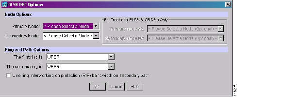
Figure 6-11 Selecting BLSR DRI Primary and Secondary Node Assignments

e. Click OK. The node information appears in the Required Nodes/Lines list, and the map graphic indicates which nodes are primary and secondary.

f. In the Circuit Constraints for Automatic Routing area, click a node or span on the circuit map.

g. Click Include to include the node or span in the circuit, or click Exclude to exclude the node or span from the circuit. The order in which you choose included nodes and spans is the order in which the circuit will be routed. Click spans twice to change the circuit direction. If you are creating a path protection to BLSR traditional handoff, exclude the unprotected links from the primary node towards the secondary node. If you are creating a path protection to BLSR integrated handoff, exclude unnecessary DRIs on the path protection segments.

h. Review the circuit constraints. To change the circuit routing order, choose a node in the Required Nodes/Links list and click the Up or Down buttons to change the circuit routing order. Click Remove to remove a node or span.

Step 20 If you selected Review Route Before Creation in Step 12, complete the following substeps; otherwise, continue with Step 21.

a. Click Next.

b. Review the circuit route. To add or delete a circuit span, choose a node on the circuit route. Blue arrows show the circuit route. Green arrows indicate spans that you can add. Click a span arrowhead, then click Include to include the span or Remove to remove the span.

c. If the provisioned circuit does not reflect the routing and configuration you want, click Back to verify and change circuit information. If the circuit needs to be routed to a different path, see the "A295 Create a Manually Routed Optical Circuit" procedure to assign the circuit route yourself.

Step 21 Click Finish. One of the following results occurs if you entered more than 1 in the Number of Circuits field on the Circuit Creation dialog box:

If you chose Auto-ranged, CTC automatically creates the number of circuits entered in the Number of Circuits field. If auto-ranging cannot complete all the circuits, for example, because sequential ports are unavailable on the source or destination, a dialog box appears. Set the new source or destination for the remaining circuits, then click Finish to continue auto-ranging. After completing the circuits, the Circuits window appears.

If you did not choose Auto-ranged, the Circuit Creation dialog box appears so you can create the remaining circuits. Repeat Steps  6 through  20 for each additional circuit. After completing the circuits, the Circuits window appears.

Step 22 In the Circuits window, verify that the circuits you created appear in the circuits list.

Step 23 Complete the following as necessary. Skip this step if you built a test circuit.

a. Complete the "A62 Test Optical Circuits" procedure.

b. Complete the "A149 Test G-Series Circuits" procedure.

Stop. You have completed this procedure.


NTP-A295 Create a Manually Routed Optical Circuit

Purpose

This procedure creates a manually routed, bidirectional or unidirectional, optical circuit, including STS-1 or concatenated STS-3c, STS-6c, STS-9c, STS-12c, STS-24c, STS-48c, or STS-192c speeds.

Tools/Equipment

OC-N cards, G-Series Ethernet, or CE-Series cards. For a G-Series circuit, a G-Series card or ML-Series card must be installed at the other end of the circuit.

For VT2 circuits, the XC-VXC-10G card must be installed at the circuit source and destination nodes.

Prerequisite Procedures

A127 Verify Network Turn Up

Required/As Needed

As needed

Onsite/Remote

Onsite or remote

Security Level

Provisioning or higher


Step 1 Complete the "DLP-A60 Log into CTC" task on page 17-68 at the node where you will create the circuit. If you are already logged in, continue with Step 2.

Step 2 If you want to assign a name to the tunnel source and destination ports before you create the circuit, complete the "DLP-A314 Assign a Name to a Port" task on page 20-8. If not, continue with Step 3.

Step 3 Complete the following as necessary (you can provision Ethernet or POS ports before or after the STS circuit is created):

To provision Ethernet ports for CE-1000-4 circuits, complete the "DLP-A509 Provision CE-1000-4 Ethernet Ports" task

To provision Ethernet ports for CE-100T-8 circuits, complete the "DLP-A513 Provision CE-100T-8 Ethernet Ports" task.

To provision POS ports for CE-100T-8 or CE-1000-4 circuits, complete the "DLP-A514 Provision CE-100T-8 and CE-1000-4 POS Ports" task.

To enable the G-Series Ethernet ports for G-Series circuits, complete the "DLP-A222 Provision G-Series Ethernet Ports" task on page 19-16.

To change the default flow control settings for G-Series or CE-1000-4 circuits, complete the "DLP-A421 Provision G-Series and CE-1000-4 Flow Control Watermarks" task on page 21-6.

Step 4 From the View menu, choose Go to Network View.

Step 5 Click the Circuits tab, then click Create.

Step 6 In the Circuit Creation dialog box, complete the following fields:

Circuit Type—Choose STS.

Number of Circuits—Enter the number of optical circuits that you want to create. The default is 1.

Auto-ranged—(Automatically routed circuits only) If you entered more than 1 in the Number of Circuits field, uncheck this box. (The box is unavailable if only one circuit is entered in the Number of Circuits field.)

Step 7 Click Next.

Step 8 Define circuit attributes:

Name—Assign a name to the circuit. The name can be alphanumeric and up to 48 characters (including spaces). Circuit names should be 43 characters or less if you want the ability to create monitor circuits. If you leave the field blank, CTC assigns a default name to the circuit.

Size—Choose the circuit size: VT2, STS-1, STS-3c, STS-6c, STS-9c, STS-12c, STS-18c, STS-24c, STS-36c, STS-48c, or STS-192c. Valid circuit sizes for a G-Series circuit are STS-1, STS-3c, STS6c, STS-9c, STS-12c, STS-24c, and STS-48c.


Note Restrictions apply to provisioning multiple circuits on a G-Series card when one of the circuit sizes provisioned is STS-24c. Refer to the Cisco ONS 15454 Reference Manual for complete information.


Bidirectional—Leave checked for this circuit (default).

Create cross-connects only (TL1-like)—Check this box if you want to create one or more cross-connects to complete a signal path for TL1-generated circuits. If you check this box, VT tunnels and Ethergroup sources and destinations are unavailable.

State—Choose the administrative state to apply to all of the cross-connects in a circuit:

IS—Puts the circuit cross-connects in the IS-NR service state.

OOS,DSBLD—Puts the circuit cross-connects in the OOS-MA,DSBLD service state. Traffic is not passed on the circuit.

IS,AINS—Puts the circuit cross-connects in the OOS-AU,AINS service state and suppresses alarms and conditions. When the connections receive a valid signal, the service state automatically changes to IS-NR.

OOS,MT—Puts the circuit cross-connects in the OOS-MA,MT service state. The maintenance state does not interrupt traffic flow; it suppresses alarms and conditions and allows loopbacks to be performed on the circuit. Use OOS,MT for circuit testing or to suppress circuit alarms temporarily. Change the administrative state to IS; IS,AINS; or OOS,DSBLD when testing is complete. See the "DLP-A230 Change a Circuit Service State" task on page 19-20.

For additional information about circuit service states, refer to the "Circuits and Tunnels" chapter in the Cisco ONS 15454 Reference Manual.

Apply to drop ports—Check this check box if you want to apply the administrative state chosen in the State field to the circuit source and destination ports. CTC applies the administrative state to the ports only if the circuit bandwidth is the same as the port bandwidth or, if the port bandwidth is larger than the circuit, the circuit must be the first circuit to use the port. If not, a Warning dialog box displays the ports where the administrative state could not be applied. If the check box is unchecked, CTC does not apply the administrative state to the source and destination ports.


Note If ports managed into the IS administrative state are not receiving signals, loss of signal alarms are generated and the port service state transitions to OOS-AU,FLT.


Protected Drops—Check this check box if you want the circuit routed to protect drops only, that is, to ONS 15454 cards that are in 1:1, 1:N, 1+1, or optimized 1+1 protection. If you check this check box, CTC provides only protected cards as source and destination choices.

Step 9 If the circuit will be routed on a path protection, complete the "DLP-A218 Provision Path Protection Selectors" task on page 19-12.

Step 10 Click Next.

Step 11 Complete the "DLP-A97 Provision an OC-N Circuit Source and Destination" task on page 17-100 for the optical circuit you are creating.

Step 12 In the Circuit Routing Preferences area ( Figure 6-10), uncheck Route Automatically.

Step 13 To set the circuit path protection, complete one of the following:

To route the circuit on a protected path, leave Fully Protected Path checked and continue with Step 14.

To create an unprotected circuit, uncheck Fully Protected Path and continue with Step 16.

To route the circuit on a BLSR protection channel, if available, uncheck Fully Protected Path, check Protection Channel Access, click Yes in the Warning dialog box, then continue with Step 16.


Caution Circuits routed on BLSR protection channels are not protected and are preempted during BLSR switches.

Step 14 If you selected Fully Protected Path in Step 13 and the circuit will be routed on a path protection, choose one of the following:

Nodal Diversity Required—Ensures that the primary and alternate paths within the path protection portions of the complete circuit path are nodally diverse.

Nodal Diversity Desired—Specifies that node diversity is preferred, but if node diversity is not possible, CTC creates fiber-diverse paths for the path protection portion of the complete circuit path.

Link Diversity Only—Specifies that only fiber-diverse primary and alternate paths for path protection portions of the complete circuit path are needed. The paths might be node-diverse, but CTC does not check for node diversity.

Step 15 If you selected Fully Protected Path in Step 13 and the circuit will be routed on a BLSR DRI or path protection DRI, check the Dual Ring Interconnect check box.

Step 16 Click Next. In the Route Review/Edit area, node icons appear for you to route the circuit manually. If you checked Dual Ring Interconnect for BLSR, continue with Step 17. If not, continue with Step 18.

Step 17 If you checked Dual Ring Interconnect in Step 15 for a BLSR DRI, complete the following substeps to assign primary and secondary nodes.

a. In the Route/Review Edit area, click the BLSR-DRI Nodes tab.

b. Click Add BLSR DRI.

c. In the BLSR DRI Options dialog box, complete the following ( Figure 6-12):

Primary Node—For a traditional or integrated BLSR-DRI, choose the node where the circuit interconnects the rings.

Secondary Node—For a traditional or integrated BLSR-DRI, choose the secondary node for the circuit to interconnect the rings. This route is used if the route on the primary node fails.

Primary Node #2—For a traditional BLSR-DRI where two primary nodes are required to interconnect rings, choose the second primary node.

Secondary Node #2—For a traditional BLSR-DRI where two secondary nodes are required, choose the second secondary node.

d. Click OK.

e. Review the circuit constraints. To change the circuit routing order, choose a node in the Required Nodes/Links list and click the Up or Down buttons to change the circuit routing order. Click Remove to remove a node or span.

f. Click the Included Spans tab, and continue with Step 18.

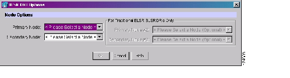
Figure 6-12 Selecting BLSR DRI Primary and Secondary Node Assignments (Manual Routing)

Step 18 Complete the "DLP-A369 Provision an OC-N Circuit Route" task on page 20-53.

Step 19 Click Finish. If the path does not meet the specified path diversity requirement, CTC displays an error message and allows you to change the circuit path. If you entered more than 1 in the Number of Circuits field on the Circuit Creation dialog box, the Circuit Creation dialog box appears after the circuit is created so you can create the remaining circuits. Repeat Steps 6 through 18 for each additional circuit.

Step 20 When all the circuits are created, the main Circuits window appears. Verify that the circuits you created appear in the window.

Step 21 Complete the following as necessary. Skip this step if you built a test circuit.

a. Complete the "A62 Test Optical Circuits" procedure.

b. Complete the "A149 Test G-Series Circuits" procedure.

Stop. You have completed this procedure.


NTP-A314 Create a Unidirectional Optical Circuit with Multiple Drops

Purpose

This procedure creates a unidirectional optical circuit with multiple traffic drops (circuit destinations).

Tools/Equipment

For VT2 circuits, the XC-VXC-10G card must be installed at the circuit source and destination nodes.

Prerequisite Procedures

A127 Verify Network Turn Up

Required/As Needed

As needed

Onsite/Remote

Onsite or remote

Security Level

Provisioning or higher


Step 1 Complete the "DLP-A60 Log into CTC" task on page 17-68 on the node where you will create the circuit. If you are already logged in, continue with Step 2.

Step 2 If you want to assign a name to the tunnel source and destination ports before you create the circuit, complete the "DLP-A314 Assign a Name to a Port" task on page 20-8. If not, continue with Step 3.

Step 3 From the View menu, choose Go to Network View.

Step 4 Click the Circuits tab, then click Create.

Step 5 In the Circuit Creation dialog box, complete the following fields:

Circuit Type—Choose STS.

Number of Circuits—Leave the default unchanged (1).

Auto-ranged—Unavailable when the Number of Circuits field is 1.

Step 6 Click Next.

Step 7 Define circuit attributes ( Figure 6-13):

Name—Assign a name to the circuit. The name can be alphanumeric and up to 48 characters (including spaces). Circuit names should be 43 characters or less if you want the ability to create monitor circuits. If you leave the field blank, CTC assigns a default name to the circuit.

Size—Choose the circuit size: VT2, STS-1, STS-3c, STS-6c, STS-9c, STS-12c, STS-18c, STS-24c, STS-36c, STS-48c, or STS-192c.

Bidirectional—Uncheck this check box for this circuit.

Create cross-connects only (TL1-like)—Check this box if you want to create one or more cross-connects to complete a signal path for TL1-generated circuits. If you check this box, VT tunnels and Ethergroup sources and destinations are unavailable.

State—Choose the administrative state to apply to all of the cross-connects in a circuit:

IS—Puts the circuit cross-connects in the IS-NR service state.

OOS,DSBLD—Puts the circuit cross-connects in the OOS-MA,DSBLD service state. Traffic is not passed on the circuit.

IS,AINS—Puts the circuit cross-connects in the OOS-AU,AINS service state and suppresses alarms and conditions. When the connections receive a valid signal, the service state automatically changes to IS-NR.

OOS,MT—Puts the circuit cross-connects in the OOS-MA,MT service state. The maintenance state does not interrupt traffic flow; it suppresses alarms and conditions and allows loopbacks to be performed on the circuit. Use OOS,MT for circuit testing or to suppress circuit alarms temporarily. Change the administrative state to IS; IS,AINS; or OOS,DSBLD when testing is complete. See the "DLP-A230 Change a Circuit Service State" task on page 19-20.

For additional information about circuit service states, refer to the "Circuits and Tunnels" chapter in the Cisco ONS 15454 Reference Manual.

Apply to drop ports—Check this check box if you want to apply the administrative state chosen in the State field to the circuit source and destination ports. CTC applies the administrative state to the ports only if the circuit bandwidth is the same as the port bandwidth or, if the port bandwidth is larger than the circuit, the circuit must be the first circuit to use the port. If not, a Warning dialog box displays the ports where the administrative state could not be applied. If the check box is unchecked, CTC does not apply the administrative state to the source and destination ports.


Note If ports managed into the IS administrative state are not receiving signals, loss of signal alarms are generated and the port service state transitions to OOS-AU,FLT.


Protected Drops—Check this check box if you want the circuit routed to protect drops only, that is, to ONS 15454 cards that are in 1:1, 1:N, 1+1, or optimized 1+1 protection. If you check this check box, CTC provides only protected cards as source and destination choices.

Figure 6-13 Setting Circuit Attributes for a Unidirectional Optical Circuit

Step 8 If the circuit will be routed on a path protection, complete the "DLP-A218 Provision Path Protection Selectors" task on page 19-12.

Step 9 Click Next.

Step 10 Complete the "DLP-A97 Provision an OC-N Circuit Source and Destination" task on page 17-100 for the circuit that you are creating.

Step 11 Uncheck Route Automatically. When Route Automatically is not selected, the Using Required Nodes/Spans and Review Route Before Circuit Creation check boxes are unavailable.

Step 12 To set the circuit path protection, complete one of the following:

To route the circuit on a protected path, leave Fully Protected Path checked and continue with Step 13. Fully protected paths might or might not have path protection path segments (with primary and alternate paths), and the path diversity options apply only to path protection path segments, if any exist.

To create an unprotected circuit, uncheck Fully Protected Path and continue with Step 15.

To route the circuit on a BLSR protection channel, if available, uncheck Fully Protected Path, check Protection Channel Access, click Yes in the Warning dialog box, then continue with Step 15.


Caution Circuits routed on BLSR protection channels are not protected and are preempted during BLSR switches.

Step 13 If you selected Fully Protected Path in Step 12 and the circuit will be routed on a path protection, choose one of the following:

Nodal Diversity Required—Ensures that the primary and alternate paths within the path protection portions of the complete circuit path are nodally diverse.

Nodal Diversity Desired—Specifies that node diversity is preferred, but if node diversity is not possible, CTC creates fiber-diverse paths for the path protection portion of the complete circuit path.

Link Diversity Only—Specifies that only fiber-diverse primary and alternate paths for path protection portions of the complete circuit path are needed. The paths might be node-diverse, but CTC does not check for node diversity.


Note For manually routed circuits, CTC checks your manually provisioned path against the path diversity option you choose. If the path does not meet the path diversity requirement that is specified, CTC displays an error message.


Step 14 If you selected Fully Protected Path in Step 12 and the circuit will be routed on a BLSR DRI or path protection DRI, check the Dual Ring Interconnect check box.

Step 15 Click Next. In the Route Review/Edit area, node icons appear for you to route the circuit manually.

a. Click a node or span on the circuit map.

b. Click Include to include the node or span in the circuit. Click Exclude to exclude the node or span from the circuit. The order in which you choose included nodes and spans is the order in which the circuit is routed. Click spans twice to change the circuit direction.

c. Repeat Steps a and b for each node or span you wish to include or exclude.

d. Review the circuit constraints. To change the circuit routing order, choose a node in the Required Nodes/Lines or Excluded Nodes Links lists and click the Up or Down buttons to change the circuit routing order. Click Remove to remove a node or span.

e. If you checked Dual Ring Interconnect for BLSR, continue with Step 16. If you did not check Dual Ring Interconnect, continue with Step 17.

Step 16 If you checked Dual Ring Interconnect in Step 14 for a BLSR DRI, complete the following substeps to assign primary and secondary nodes. Otherwise, continue with Step 17.

a. In the Route/Review Edit area, click the BLSR-DRI Nodes tab.

b. Click Add BLSR DRI.

c. In the Node Options area of the BLSR DRI Options dialog box, complete the following ( Figure 6-11):

Primary Node—For a traditional or integrated BLSR-DRI, choose the node where the circuit interconnects the rings.

Secondary Node—For a traditional or integrated BLSR-DRI, choose the secondary node for the circuit to interconnect the rings. This route is used if the route on the primary node fails.

Primary Node #2—For a traditional BLSR-DRI where two primary nodes are required to interconnect rings, choose the second primary node.

Secondary Node #2—For a traditional BLSR-DRI where two secondary nodes are required, choose the second secondary node.

d. In the Ring and Path Options area, complete the following:

The first ring is—Choose UPSR or BLSR from the drop-down list.

The second ring is—Choose UPSR or BLSR from the drop-down list.

Use ring interworking protection (RIP) on secondary path—Check this box to carry the secondary spans on the protection channels. These spans will be preempted during a ring/span switch.

e. Click OK.

f. Review the circuit constraints. To change the circuit routing order, choose a node in the Required Nodes/Links list and click the Up or Down buttons to change the circuit routing order. Click Remove to remove a node or span.

g. Click the Included Spans tab, and continue with Step 18.

Step 17 Complete the "DLP-A369 Provision an OC-N Circuit Route" task on page 20-53.

Step 18 Click Finish. After completing the circuit, the Circuits window appears.

Step 19 In the Circuits window, click the circuit that you want to route to multiple drops. The Delete, Edit, and Search buttons become active.

Step 20 Click Edit. The Edit Circuit window appears with the General tab selected. All nodes in the DCC network appear on the network map. Circuit source and destination information appears under the source and destination nodes. To see a detailed view of the circuit, click Show Detailed Map. You can rearrange the node icons by pressing Ctrl while you drag and drop the icon to the new location.

Step 21 In the Edit Circuit dialog box, click the Drops tab. A list of existing drops appears.

Step 22 Click Create.

Step 23 In the Define New Drop dialog box, define the new drop:

a. Node—Choose the target node for the circuit drop.

b. Slot—Choose the target card and slot.

c. Port, STS—Choose the port and/or STS from the Port and STS drop-down lists. The choice in these menus depends on the card selected in Step b. See Table 6-2 for a list of options.

d. The routing preferences for the new drop match those of the original circuit. However, if the following options are available, you can modify them:

If the original circuit was routed on a protected path protection path, you can change the nodal diversity options: Nodal Diversity Required, Nodal Diversity Desired, or Link Diversity Only. See Step 13 for option descriptions.

If the original circuit was not routed on a protected path, the Protection Channel Access option is available. See Step 12 for a description of the PCA option.

e. If you want to change the circuit state, choose the circuit state from the Target Circuit Admin State drop-down list. The state chosen applies to the entire circuit.

f. Check Apply to drop ports if you want to apply the state chosen in the Target Circuit Admin State to the circuit source and destination drops. For the requirements necessary to apply a service state to drop ports, refer to the Cisco ONS 15454 Reference Manual.

g. Click Finish. The new drop appears in the Drops list.

Step 24 If you need to create additional drops on the circuit, repeat Steps 21 through 23.

Step 25 Click Close. The Circuits window appears.

Step 26 Verify that the new drops appear in the Destination column for the circuit you edited. If they do not appear, repeat Steps 22 through 25, making sure all options are provisioned correctly.

Step 27 Complete the "A62 Test Optical Circuits" procedure.

Stop. You have completed this procedure.


NTP-A62 Test Optical Circuits

Purpose

This procedure tests an optical circuit. Required if you created an optical circuit.

Tools/Equipment

Test set capable of optical speeds, appropriate fibers, and attenuators

Prerequisite Procedures

This procedure assumes that you completed facility loopback tests to test the fibers and cables from the source and destination ONS 15454s to the fiber distribution page or the DSX, and one of following circuit procedures:

A257 Create an Automatically Routed Optical Circuit

A295 Create a Manually Routed Optical Circuit

A314 Create a Unidirectional Optical Circuit with Multiple Drops

Required/As Needed

As needed

Onsite/Remote

Onsite

Security Level

Provisioning or higher


Step 1 Complete the "DLP-A60 Log into CTC" task on page 17-68 at the node where you created the circuit.

Step 2 From the View menu, choose Go to Network View.

Step 3 Click the Circuits tab.

Step 4 Complete the "DLP-A230 Change a Circuit Service State" task on page 19-20 to set the circuit and circuit ports to the OOS-MA,MT service state.

Step 5 Set up the patch cable at the destination node:

a. Test the patch cable by connecting one end to the test set Tx port and the other end to the test Rx port. If the test set does not run error-free, check the cable for damage and check the test set to make sure it is set up correctly.

b. Install the loopback cable on the port you are testing. Connect the Tx connector to the Rx connector of the port being tested.

Step 6 Set up the patch cable at the source node:

a. Test the loopback cable by connecting one end to the test set Tx port and the other end to the test Rx port. If the test set does not run error-free, check the cable for damage and check the test set to make sure it is set up correctly.

b. At the source node, attach the loopback cable to the port you are testing. Connect the test set to the circuit source port. Connect the Tx port of the test set to the circuit Rx port, and the test set Rx port to the circuit Tx port.

Step 7 Configure the test set for the source ONS 15454 card:

OC-3 cards—You will test either an OC-3c or a multiplexed OC-3. If you are testing an OC-3c, configure the test set for an OC-3c. If you are testing a multiplexed OC-3, configure the test set for a multiplexed OC-3 and choose the DS-3 and/or DS-1 you will test. For information about configuring your test set, consult your test set user guide.

OC-12 cards—You will test either an OC-12c or a multiplexed OC-12. If you are testing an OC-12c, configure the test set for an OC-12c. If you are testing a multiplexed OC-12, configure the test set for a multiplexed OC-12 and choose the DS-3 and/or DS-1 you will test. For information about configuring your test set, consult your test set user guide.

OC-48 cards—You will test either an OC-48c or a multiplexed OC-48. If you are testing an OC-48c, configure the test set for an OC-48c. If you are testing a multiplexed OC-48, configure the test set for a multiplexed OC-48 and choose the DS-3 and/or DS-1 you will test. For information about configuring your test set, consult your test set user guide.

OC-192 cards—You will test an OC-192c or a multiplexed OC-192. If you are testing an OC-192c, configure the test set for an OC-192c. If you are testing a multiplexed OC-192, configure the test set for a multiplexed OC-192 and choose the DS-3 and/or DS-1 you will test. For information about configuring your test set, consult your test set user guide.

Step 8 Verify that the test set shows a clean signal. If a clean signal does not appear, repeat Steps 2 through 7 to make sure that you have configured the test set and cabling correctly.

Step 9 Inject errors from the test set. Verify that the errors appear at the source and destination nodes.

Step 10 Clear the PM counts for the ports that you tested. See the "DLP-A349 Clear Selected PM Counts" task on page 20-36 for instructions.

Step 11 Perform protection switch testing appropriate to the SONET topology:

For path protection configurations, see the "DLP-A94 Path Protection Switching Test" task on page 17-97.

For BLSRs, see the "DLP-A91 BLSR Switch Test" task on page 17-89.

Step 12 Perform a BERT for 12 hours or follow your site requirements for length of time. For information about configuring your test set for the BERT, see your test set user guide.

Step 13 After the BERT is complete, print the results or save them to a disk for future reference. For information about printing or saving test results, see your test set user guide.

Step 14 Complete the "DLP-A230 Change a Circuit Service State" task on page 19-20 to change the circuit and circuit ports from OOS-MA,MT to their previous service states.

Stop. You have completed this procedure.


NTP-A139 Create a Half Circuit on a BLSR or 1+1 Node

Purpose

This procedure creates a DS-1, DS-3, or optical circuit from a drop card to an OC-N or G-Series trunk card on the same node in a BLSR or 1+1 topology.

Tools/Equipment

None

Prerequisite Procedures

A127 Verify Network Turn Up

Required/As Needed

As needed

Onsite/Remote

Onsite or remote

Security Level

Provisioning or higher


Step 1 Complete the "DLP-A60 Log into CTC" task on page 17-68 at the node on the network where you will create the half circuit. If you are already logged in, continue with Step 2.

Step 2 If you want to assign a name to the circuit source and destination ports before you create the circuit, complete the "DLP-A314 Assign a Name to a Port" task on page 20-8. If not, continue with Step 3.

Step 3 From the View menu, choose Go to Network View.

Step 4 Click the Circuits tab, then click Create.

Step 5 In the Circuit Creation dialog box, complete the following fields:

Circuit Type—For DS-1 circuits, choose VT. VT cross-connects will carry the DS-1 circuit across the ONS 15454 network. For DS-3 or optical circuits, choose STS. STS cross-connects will carry the DS-3 circuit across the ONS 15454 network.

Number of Circuits—Enter the number of circuits that you want to create. The default is 1.

Auto-ranged—Uncheck this check box; it is automatically selected if you enter more than 1 in the Number of Circuits field.

Step 6 Click Next.

Step 7 Define the circuit attributes:

Name—Assign a name to the circuit. The name can be alphanumeric and up to 48 characters (including spaces). Circuit names should be 43 characters or less if you want the ability to create monitor circuits. If you leave the field blank, CTC assigns a default name to the circuit.

Size—For DS-3 or optical circuits, choose STS-1. For DS-1 circuits, VT1.5 is the default. You cannot change it.

Bidirectional—Leave checked for this circuit (default).

Create cross-connects only (TL1-like)—Check this box if you want to create one or more cross-connects to complete a signal path for TL1-generated circuits. If you check this box, VT tunnels and Ethergroup sources and destinations are unavailable.

State—Choose the administrative state to apply to all of the cross-connects in a circuit:

IS—Puts the circuit cross-connects in the IS-NR service state.

OOS,DSBLD—Puts the circuit cross-connects in the OOS-MA,DSBLD service state. Traffic is not passed on the circuit.

IS,AINS—Puts the circuit cross-connects in the OOS-AU,AINS service state and suppresses alarms and conditions. When the connections receive a valid signal, the service state automatically changes to IS-NR.

OOS,MT—Puts the circuit cross-connects in the OOS-MA,MT service state. The maintenance state does not interrupt traffic flow; it suppresses alarms and conditions and allows loopbacks to be performed on the circuit. Use OOS,MT for circuit testing or to suppress circuit alarms temporarily. Change the administrative state to IS; IS,AINS; or OOS,DSBLD when testing is complete. See the "DLP-A230 Change a Circuit Service State" task on page 19-20.

For additional information about circuit service states, refer to the "Circuits and Tunnels" chapter in the Cisco ONS 15454 Reference Manual.

Apply to drop ports—Check this check box if you want to apply the administrative state chosen in the State field to the circuit source and destination ports. CTC applies the administrative state to the ports only if the circuit bandwidth is the same as the port bandwidth or, if the port bandwidth is larger than the circuit, the circuit must be the first circuit to use the port. If not, a Warning dialog box displays the ports where the administrative state could not be applied. If the check box is unchecked, CTC does not apply the administrative state to the source and destination ports.


Note If ports managed into the IS administrative state are not receiving signals, loss of signal alarms are generated and the port service state transitions to OOS-AU,FLT.


Protected Drops—Uncheck this box.

Step 8 Click Next.

Step 9 Complete the "DLP-A311 Provision a Half Circuit Source and Destination on a BLSR or 1+1 Configuration" task on page 20-5.

Step 10 Click Finish. One of the following results occurs if you entered more than 1 in the Number of Circuits field on the Circuit Creation dialog box:

If you chose Auto-ranged, CTC automatically creates the number of circuits entered in the Number of Circuits field. If auto-ranging cannot complete all the circuits, for example, because sequential ports are unavailable at the source or destination, a dialog box appears. Set the new source or destination for the remaining circuits, then click Finish to continue auto-ranging. After completing the circuits, the Circuits window appears.

If you did not choose Auto-ranged, the Circuit Creation dialog box appears so you can create the remaining circuits. Repeat Steps 5 through  9 for each additional circuit. After completing the circuits, the Circuits window appears.

Step 11 In the Circuits window, verify that the new circuits appear in the circuits list.

Step 12 Complete the "A135 Test Electrical Circuits" procedure or the "A62 Test Optical Circuits" procedure, as applicable. Skip this step if you built a test circuit.

Stop. You have completed this procedure.


NTP-A140 Create a Half Circuit on a Path Protection Node

Purpose

This procedure creates a DS-1, DS-3, or optical circuit from a drop to an OC-N or G-Series line card on the same path protection node.

Tools/Equipment

None

Prerequisite Procedures

A127 Verify Network Turn Up

Required/As Needed

As needed

Onsite/Remote

Onsite or remote

Security Level

Provisioning or higher


Step 1 Complete the "DLP-A60 Log into CTC" task on page 17-68 at the node where you will create the circuit. If you are already logged in, continue with Step 2.

Step 2 If you want to assign a name to the circuit source and destination ports before you create the circuit, complete the "DLP-A314 Assign a Name to a Port" task on page 20-8. If not, continue with Step 3.

Step 3 From the View menu, choose Go to Network View.

Step 4 Click the Circuits tab, then click Create.

Step 5 In the Circuit Creation dialog box, complete the following fields:

Circuit Type—For DS-1 circuits, choose VT. VT cross-connects will carry the DS-1 circuit across the ONS 15454 network. For DS-3 or optical circuits, choose STS. STS cross-connects will carry the DS-3 circuit across the ONS 15454 network.

Number of Circuits—Enter the number of circuits that you want to create. The default is 1.

Auto-ranged—Uncheck this check box; it is automatically selected if you enter more than 1 in the Number of Circuits field.

Step 6 Click Next.

Step 7 Define the circuit attributes:

Name—Assign a name to the circuit. The name can be alphanumeric and up to 48 characters (including spaces). Circuit names should be 43 characters or less if you want the ability to create monitor circuits. If you leave the field blank, CTC assigns a default name to the circuit.

Size—For DS-1 circuits, VT1.5 is the default. You cannot change it. For DS-3 or optical circuits, choose STS-1.

Bidirectional—Leave checked for this circuit (default).

Create cross-connects only (TL1-like)—Check this box if you want to create one or more cross-connects to complete a signal path for TL1-generated circuits. If you check this box, VT tunnels and Ethergroup sources and destinations are unavailable.

State—Choose the administrative state to apply to all of the cross-connects in a circuit:

IS—Puts the circuit cross-connects in the IS-NR service state.

OOS,DSBLD—Puts the circuit cross-connects in the OOS-MA,DSBLD service state. Traffic is not passed on the circuit.

IS,AINS—Puts the circuit cross-connects in the OOS-AU,AINS service state and suppresses alarms and conditions. When the connections receive a valid signal, the service state automatically changes to IS-NR.

OOS,MT—Puts the circuit cross-connects in the OOS-MA,MT service state. The maintenance state does not interrupt traffic flow; it suppresses alarms and conditions and allows loopbacks to be performed on the circuit. Use OOS,MT for circuit testing or to suppress circuit alarms temporarily. Change the administrative state to IS; IS,AINS; or OOS,DSBLD when testing is complete. See the "DLP-A230 Change a Circuit Service State" task on page 19-20.

For additional information about circuit service states, refer to the "Circuits and Tunnels" chapter in the Cisco ONS 15454 Reference Manual.

Apply to drop ports—Check this check box if you want to apply the administrative state chosen in the State field to the circuit source and destination ports. CTC applies the administrative state to the ports only if the circuit bandwidth is the same as the port bandwidth or, if the port bandwidth is larger than the circuit, the circuit must be the first circuit to use the port. If not, a Warning dialog box displays the ports where the administrative state could not be applied. If the check box is unchecked, CTC does not apply the administrative state to the source and destination ports.


Note If ports managed into the IS administrative state are not receiving signals, loss of signal alarms are generated and the port service state transitions to OOS-AU,FLT.


Protected Drops—Leave this box unchecked.

Step 8 Set the path protection path selectors. See the "DLP-A218 Provision Path Protection Selectors" task on page 19-12.

Step 9 Click Next.

Step 10 Complete the "DLP-A312 Provision a Half Circuit Source and Destination on a Path Protection" task on page 20-6.

Step 11 Click Finish. One of the following results occurs if you entered more than 1 in the Number of Circuits field on the Circuit Creation dialog box:

If you chose Auto-ranged, CTC automatically creates the number of circuits entered in the Number of Circuits field. If auto-ranging cannot complete all the circuits, for example, because sequential ports are unavailable at the source or destination, a dialog box appears. Set the new source or destination for the remaining circuits, then click Finish to continue auto-ranging. After completing the circuits, the Circuits window appears.

If you did not choose Auto-ranged, the Circuit Creation dialog box appears so you can create the remaining circuits. Repeat Steps 5 through  10 for each additional circuit. After completing the circuits, the Circuits window appears.

Step 12 In the Circuits window, verify that the new circuits appear in the circuits list.

Step 13 Complete the "A135 Test Electrical Circuits" procedure or the "A62 Test Optical Circuits" procedure, as applicable. Skip this step if you built a test circuit.

Stop. You have completed this procedure.


NTP-A191 Create an E-Series EtherSwitch Circuit (Multicard or Single-Card Mode)

Purpose

This procedure creates a multicard or single-card EtherSwitch circuit. It does not apply to E-Series cards in port-mapped mode. To create a port-mapped mode circuit, see A192 Create a Circuit for an E-Series Card in Port-Mapped Mode.

Tools/Equipment

E-Series Ethernet cards (E100T-12/E100T-G, E1000-2/E1000-2-G) must be installed at each end of the Ethernet circuit.

Prerequisite Procedures

A127 Verify Network Turn Up

Required/As Needed

As needed

Onsite/Remote

Onsite or remote

Security Level

Provisioning or higher


Step 1 Complete the "DLP-A60 Log into CTC" task on page 17-68 at the node where you will create the EtherSwitch circuit. If you are already logged in, continue with Step 2.

Step 2 If the network is already using a high number of VLANs, complete the "DLP-A99 Determine Available VLANs" task on page 17-101 to verify that sufficient VLAN capacity is available. (You will create a VLAN during each circuit creation task.)

Step 3 If enough VLANs are not available, complete the "DLP-A335 Delete VLANs" task on page 20-23 to free space.

Step 4 Verify that the circuit source and destination Ethernet cards are provisioned for the mode of the circuit that you will create, either multicard or single-card. See the "DLP-A246 Provision E-Series Ethernet Card Mode" task on page 19-29.

Step 5 Provision and enable the Ethernet ports. See the "DLP-A220 Provision E-Series Ethernet Ports" task on page 19-13.

Step 6 From the View menu, choose Go to Network View.

Step 7 Click the Circuits tab, then click Create.

Step 8 In the Create Circuits dialog box, complete the following fields:

Circuit Type—Choose STS.

Number of Circuits—Leave the default unchanged (1).

Auto-ranged—Unavailable.

Step 9 Click Next.

Step 10 Define the circuit attributes:

Name—Assign a name to the circuit. The name can be alphanumeric and up to 48 characters (including spaces). Circuit names should be 43 characters or less if you want the ability to create monitor circuits. If you leave the field blank, CTC assigns a default name to the circuit.

Size—Choose the circuit size. Valid circuit sizes for an Ethernet multicard circuit are STS-1, STS-3c, and STS6c. Valid circuit sizes for an Ethernet single-card circuit are STS-1, STS-3c, STS6c, and STS12c.

Bidirectional—Leave the default unchanged (checked).

Create cross-connects only (TL1-like)—Uncheck this box; it does not apply to Ethernet circuits.

State—Choose IS (in service). Ethergroup circuits are stateless and always in service.

Apply to drop ports—Uncheck this box; states cannot be applied to E-Series Ethernet card ports.

Protected Drops—Leave the default unchanged (unchecked).

Step 11 If the circuit will be routed on a path protection, complete the "DLP-A218 Provision Path Protection Selectors" task on page 19-12.


Caution Layer 1 SONET protection does not extend to multicard EtherSwitch circuits on path protection.


Caution A TCC2/TCC2P card reset disrupts single-card and multicard EtherSwitch circuits for 45 seconds to two minutes. During this time, a spanning tree topology is created by the newly activated TCC2/TCC2P card.

Step 12 Click Next.

Step 13 Provision the circuit source:

a. From the Node drop-down list, choose one of the EtherSwitch circuit endpoint nodes. (Either end node can be the EtherSwitch circuit source.)

b. From the Slot drop-down list, choose one of the following:

If you are building a multicard EtherSwitch circuit, choose Ethergroup.

If you are building a single-card EtherSwitch circuit, choose the Ethernet card where you enabled the single-card EtherSwitch.

Step 14 Click Next.

Step 15 Provision the circuit destination:

a. From the Node drop-down list, choose the second EtherSwitch circuit endpoint node.

b. From the Slot drop-down list, choose one of the following:

If you are building a multicard EtherSwitch circuit, choose Ethergroup.

If you are building a single-card EtherSwitch circuit, choose the Ethernet card where you enabled the single-card EtherSwitch.

Step 16 Click Next.

Step 17 In the Circuit VLAN Selection area, click New VLAN. If the desired VLAN already exists, continue with Step 20.


Tip You can also add VLANs in network view by choosing Tools > Manage VLANs. In the All VLANs dialog box, click the Create button to open the Define New VLAN dialog box.


Step 18 In the Define New VLAN dialog box, complete the following:

VLAN Name—Assign an easily identifiable name to your VLAN.

VLAN ID—Assign a VLAN ID. The VLAN ID should be the next available number between 2 and 4093 that is not already assigned to an existing VLAN. Each ONS 15454 network supports a maximum of 509 user-provisionable VLANs.

Topology Host—Choose the node to serve as the topology host from the drop-down list.

Step 19 Click OK.

Step 20 In the Circuit VLAN Selection area, highlight the VLAN name and click the arrow button (>>) to move the available VLANs to the Circuit VLANs column.

Step 21 If you are building a single-card EtherSwitch circuit and want to disable spanning tree protection on this circuit, uncheck the Enable Spanning Tree check box and click OK in the Disabling Spanning Tree dialog box. The Enable Spanning Tree box remains checked or unchecked for the creation of the next single-card, point-to-point Ethernet circuit.


Caution Disabling spanning-tree protection increases the likelihood of logic loops on an Ethernet network.


Caution Turning off spanning tree on a circuit-by-circuit basis means that the ONS 15454 is no longer protecting the Ethernet circuit and that the circuit must be protected by another mechanism in the Ethernet network.


Caution Multiple circuits with spanning tree protection enabled incur blocking if the circuits traverse the same E-Series card and use the same VLAN.


Note Spanning-tree rules prevent users from creating new circuits or modifying existing circuits if the circuits do not meet certain VLAN assignment constraints. If the VLAN set of the new circuit overlaps existing circuits, the same spanning-tree instance is used for all circuits. If the VLAN set of the new circuit overlaps with VLAN sets of existing circuits with different spanning-tree instances, the VLAN assignment fails. Cisco recommends that you plan VLAN assignments so that circuits with larger VLAN sets and a higher chance of overlap are added first. This means that if a circuit with an overlapping VLAN set is added, it collapses into the same spanning tree. To view circuits mapped to a spanning tree and their VLAN assignments, see the "DLP-A430 View Spanning Tree Information" task on page 21-9.


Note You can disable or enable spanning tree protection on a circuit-by-circuit basis only for single-card, point-to-point Ethernet circuits. Other E-Series Ethernet configurations disable or enable spanning tree on a port-by-port basis.


Step 22 Click Next.

Step 23 In the Circuit Attributes area, confirm that the following information is correct:

Circuit name

Circuit type

Circuit size

ONS nodes

Step 24 If the information is not correct, click the Back button and repeat Steps 8 through 23 with the correct information. If the information is correct, check Route Automatically.

Step 25 Click Finish.

Step 26 Complete the "DLP-A221 Provision E-Series Ethernet Ports for VLAN Membership" task on page 19-14.

Step 27 Complete the "A146 Test E-Series Circuits" procedure.

Stop. You have completed this procedure.


NTP-A192 Create a Circuit for an E-Series Card in Port-Mapped Mode

Purpose

This procedure creates an E-Series point-to-point SONET circuit with an E-Series card in port-mapped mode.

Tools/Equipment

An E-Series Ethernet card must be installed at each end of the circuit and configured in port-mapped mode.

Prerequisite Procedures

A127 Verify Network Turn Up

Required/As Needed

As needed

Onsite/Remote

Onsite or remote

Security Level

Provisioning or higher


Step 1 Complete the "DLP-A60 Log into CTC" task on page 17-68 at the node where you will create the circuit. If you are already logged in, continue with Step 4.

Step 2 Provision the Ethernet cards that will carry the circuit for port-mapped mode. See the "DLP-A246 Provision E-Series Ethernet Card Mode" task on page 19-29.

Step 3 Complete the "DLP-A220 Provision E-Series Ethernet Ports" task on page 19-13.

Step 4 From the View menu, choose Go to Network View.

Step 5 Click the Circuits tab and click Create.

Step 6 In the Create Circuits dialog box, complete the following fields:

Circuit Type—Choose STS.

Number of Circuits—Leave the default unchanged (1).

Auto-ranged—Unavailable.

Step 7 Click Next.

Step 8 Define the circuit attributes:

Name—Assign a name to the circuit. The name can be alphanumeric and up to 48 characters (including spaces). Circuit names should be 43 characters or less if you want the ability to create monitor circuits. If you leave the field blank, CTC assigns a default name to the circuit.

Size—Choose the circuit size. Valid circuit sizes for an E-Series circuit are STS-1, STS-3c, STS6c, and STS-12c.

Bidirectional—Leave the default unchanged (checked).

Create cross-connects only (TL1-like)—Uncheck this box.

State—Choose the administrative state to apply to all of the cross-connects in a circuit:

IS—Puts the circuit cross-connects in the IS-NR service state.

OOS,DSBLD—Puts the circuit cross-connects in the OOS-MA,DSBLD service state. Traffic is not passed on the circuit.

IS,AINS—Puts the circuit cross-connects in the OOS-AU,AINS service state and suppresses alarms and conditions. When the connections receive a valid signal, the service state automatically changes to IS-NR.

OOS,MT—Puts the circuit cross-connects in the OOS-MA,MT service state. The maintenance state does not interrupt traffic flow; it suppresses alarms and conditions and allows loopbacks to be performed on the circuit. Use OOS,MT for circuit testing or to suppress circuit alarms temporarily. Change the administrative state to IS; IS,AINS; or OOS,DSBLD when testing is complete. See the "DLP-A230 Change a Circuit Service State" task on page 19-20.

For additional information about circuit service states, refer to the "Circuits and Tunnels" chapter in the Cisco ONS 15454 Reference Manual.

Apply to drop ports—Check this check box if you want to apply the state chosen in the State field (IS or OOS-MT only) to the Ethernet circuit source and destination ports. You cannot apply OOS-AINS to E-Series Ethernet card ports. CTC applies the circuit state to the ports only if the circuit bandwidth is the same as the port bandwidth or, if the port bandwidth is larger than the circuit, the circuit must be the first circuit to use the drop port. If not, a Warning dialog box shows the ports where the circuit state could not be applied. If the box is unchecked, CTC does not change the state of the source and destination ports. For the requirements necessary to apply a service state to drop ports, refer to the Cisco ONS 15454 Reference Manual.


Note If ports managed into the IS administrative state are not receiving signals, loss of signal alarms are generated and the port service state transitions to OOS-AU,FLT.


Auto-ranged—Unavailable.

Protected Drops—Leave the default unchanged (unchecked).

Step 9 If the circuit will be routed on a path protection, complete the "DLP-A218 Provision Path Protection Selectors" task on page 19-12.

Step 10 Click Next.

Step 11 Provision the circuit source:

a. From the Node drop-down list, choose the circuit source node. Either end node can be the point-to-point circuit source.

b. From the Slot drop-down list, choose the slot containing the E-Series card that you will use for one end of the point-to-point circuit.

c. From the Port drop-down list, choose a port.

Step 12 Click Next.

Step 13 Provision the circuit destination:

a. From the Node drop-down list, choose the circuit destination node.

b. From the Slot drop-down list, choose the slot containing the E-Series card that you will use for other end of the point-to-point circuit.

c. From the Port drop-down list, choose a port.

Step 14 Click Next.

Step 15 In the Circuit Attributes area, confirm that the following information is correct:

Circuit name

Circuit type

Circuit size

ONS nodes

Step 16 If the information is not correct, click the Back button and repeat Steps 6 through 15 with the correct information. If the information is correct, check Route Automatically.

Step 17 Click Finish.

Step 18 Complete the "A146 Test E-Series Circuits" procedure.

Stop. You have completed this procedure.


NTP-A142 Create an E-Series Shared Packet Ring Ethernet Circuit

Purpose

This procedure creates a shared packet ring Ethernet circuit. It does not apply to E-Series cards in port-mapped mode.

Tools/Equipment

E-Series Ethernet cards (E100T-12/E100T-G, E1000-2/E1000-2-G) must be installed at both Ethernet circuit endpoint nodes.

Prerequisite Procedures

A127 Verify Network Turn Up

Required/As Needed

As needed

Onsite/Remote

Onsite or remote

Security Level

Provisioning or higher


Step 1 Complete the "DLP-A60 Log into CTC" task on page 17-68 at the node where you will create the circuit. If you are already logged in, continue with Step 2.

Step 2 If a high number of VLANs is already used by the network, complete the "DLP-A99 Determine Available VLANs" task on page 17-101 to verify that sufficient VLAN capacity is available. (You will create a VLAN during each circuit creation task.)

Step 3 Verify that the Ethernet cards that will carry the circuit are provisioned for the Multicard EtherSwitch Group. See the "DLP-A246 Provision E-Series Ethernet Card Mode" task on page 19-29.

Step 4 Provision and enable the Ethernet ports. See "DLP-A220 Provision E-Series Ethernet Ports" task on page 19-13.

Step 5 From the View menu, choose Go to Network View.

Step 6 Click the Circuits tab and click Create.

Step 7 In the Create Circuits dialog box, complete the following fields:

Circuit Type—Choose STS.

Number of Circuits—Leave the default unchanged (1).

Auto-ranged—Unavailable.

Step 8 Click Next.

Step 9 Define the circuit attributes:

Name—Assign a name to the circuit. The name can be alphanumeric and up to 48 characters (including spaces). Circuit names should be 43 characters or less if you want the ability to create monitor circuits. If you leave the field blank, CTC assigns a default name to the circuit.

Size—Choose the circuit size. Valid shared packet ring circuit sizes are STS-1, STS-3c, and STS6c.

Bidirectional—Leave the default unchanged (checked).

Create cross-connects only (TL1-like)—Uncheck this box; it does not apply to Ethernet circuits.

State—The circuit is in service (default).

Apply to drop ports—Uncheck this box; states cannot be applied to E-Series ports.

Protected Drops—Leave the default unchanged (unchecked).

Step 10 If the circuit will be routed on a path protection, complete the "DLP-A218 Provision Path Protection Selectors" task on page 19-12.


Caution Layer 1 SONET protection does not extend to multicard EtherSwitch circuits on path protection.

Step 11 Click Next.

Step 12 Provision the circuit source:

a. From the Node drop-down list, choose one of the shared packet ring circuit endpoint nodes. (Either end node can be the shared packet ring circuit source.)

b. From the Slot drop-down list, choose Ethergroup.

Step 13 Click Next.

Step 14 Provision the circuit destination:

a. From the Node drop-down list, choose the second shared packet ring circuit endpoint node.

b. From the Slot drop-down list, choose Ethergroup.

Step 15 Click Next.

Step 16 Review the VLANs listed in the Available VLANs list. If the VLAN you want to use appears, continue with Step 17. If you need to create a new VLAN, complete the following steps:

a. Click the New VLAN button.

b. In the Define New VLAN dialog box, complete the following:

VLAN Name—Assign an easily identifiable name to your VLAN.

VLAN ID—Assign a VLAN ID. The VLAN ID should be the next available number between 2 and 4093 that is not already assigned to an existing VLAN. Each ONS 15454 network supports a maximum of 509 user-provisionable VLANs.

Topology Host—Choose the topology host ID from the drop-down list.

c. Click OK.


Tip You can also add VLANs in network view by choosing Tools > Manage VLANs. In the All VLANs dialog box, click the Create button to open the Define New VLAN dialog box.


Step 17 In the Available VLANs column, click the VLAN that you want to use and click the arrow button (>>) to move the VLAN to the Circuit VLANs column.


Note Moving the VLAN from Available VLANs to Circuit VLANs forces all the VLAN traffic to use the shared packet ring you are creating.


Step 18 Click Next.

Step 19 In the Circuit Routing Preferences area, uncheck the Route Automatically check box and click Next.

Step 20 In the Route Review and Edit area, click the source node, then click a span (green arrow) leading away from the source node.

The span turns white.

Step 21 Click Add Span.

The span turns blue. CTC adds the span to the Included Spans list.

Step 22 Click the node at the end of the blue span.

Step 23 Click the green span joining the node selected in Step 22.

The span turns white.

Step 24 Click Add Span.

The span turns blue.

Step 25 Repeat Steps 21 through 24 for every node in the ring.

Step 26 In the Route Review and Edit area, verify that the new circuit is correctly configured. If the circuit information is not correct, click the Back button and repeat Steps 7 through 25 with the correct information.


Note If the circuit is incorrect, you can also click Finish, delete the completed circuit, and begin the procedure again.


Step 27 Click Finish.

Step 28 Complete the "DLP-A220 Provision E-Series Ethernet Ports" task on page 19-13 for each node that carries the circuit.

Step 29 Complete the "DLP-A221 Provision E-Series Ethernet Ports for VLAN Membership" task on page 19-14 for each node that carries the circuit.

Step 30 Complete the "A146 Test E-Series Circuits" procedure.

Stop. You have completed this procedure.


NTP-A143 Create an E-Series Hub-and-Spoke Ethernet Configuration

Purpose

This procedure creates a hub-and-spoke Ethernet configuration, which is made up of multiple circuits that share a common endpoint. It does not apply to E-Series cards in port-mapped mode.

Tools/Equipment

E-Series Ethernet cards (E100T-12/E100T-G, E1000-2/E1000-2-G) must be installed at all Ethernet circuit endpoint nodes.

Prerequisite Procedures

A127 Verify Network Turn Up

Required/As Needed

As needed

Onsite/Remote

Onsite or remote

Security Level

Provisioning or higher


Step 1 Complete the "DLP-A60 Log into CTC" task on page 17-68 at the hub node (the common endpoint). If you are already logged in, continue with Step 2.

Step 2 Complete the "DLP-A99 Determine Available VLANs" task on page 17-101 to verify that sufficient VLAN capacity is available. (You will create a VLAN during each circuit creation task.)

Step 3 Display the node view.

Step 4 Verify that the Ethernet card that will carry the hub-and-spoke circuit is provisioned for Single-card EtherSwitch Group. See the "DLP-A246 Provision E-Series Ethernet Card Mode" task on page 19-29.

Step 5 Provision and enable the Ethernet ports. See "DLP-A220 Provision E-Series Ethernet Ports" task on page 19-13.

Step 6 Log into a spoke endpoint node and repeat Steps 3 through 5 for the destination Ethernet card. You only need to verify that the hub node is provisioned for single-card EtherSwitch once.

Step 7 Click the Circuits tab and click Create.

Step 8 In the Create Circuits dialog box, complete the following fields:

Circuit Type—Choose STS.

Number of Circuits—Leave the default unchanged (1).

Auto-ranged—Unavailable.

Step 9 Click Next.

Step 10 Define the circuit attributes:

Name—Assign a name to the circuit. The name can be alphanumeric and up to 48 characters (including spaces). Circuit names should be 43 characters or less if you want the ability to create monitor circuits. If you leave the field blank, CTC assigns a default name to the circuit.

Size—Choose the circuit size.

Bidirectional—Leave the default unchanged (checked).

Create cross-connects only (TL1-like)—Uncheck this box; it does not apply to Ethernet circuits.

State—The circuit is in service (default).

Apply to drop ports—Uncheck this box; states cannot be applied to E-Series ports.

Protected Drops—Leave the default unchanged (unchecked).

Step 11 If the circuit will be routed on a path protection, complete the "DLP-A218 Provision Path Protection Selectors" task on page 19-12.

Step 12 Click Next.

Step 13 Provision the circuit source:

a. From the Node drop-down list, choose the hub node.

b. From the Slot drop-down list, choose the Ethernet card where you enabled the single-card EtherSwitch.

Step 14 Click Next.

Step 15 Provision the circuit destination:

a. From the Node drop-down list, choose an EtherSwitch circuit endpoint node.

b. From the Slot drop-down list, choose the Ethernet card where you enabled the single-card EtherSwitch.

Step 16 Click Next.

Step 17 Review the VLANs listed in the Available VLANs list. If the VLAN you want to use appears, continue with Step 19. If you need to create a new VLAN, complete the following steps:

a. Click the New VLAN button.

b. In the Define New VLAN dialog box, complete the following:

VLAN Name—Assign an easily identifiable name to your VLAN.

VLAN ID—Assign a VLAN ID. The VLAN ID should be the next available number between 2 and 4093 that is not already assigned to an existing VLAN. Each ONS 15454 network supports a maximum of 509 user-provisionable VLANs.

Topology Host—Choose the topology host ID from the drop-down list.

c. Click OK.


Tip You can also add VLANs in network view by choosing Tools > Manage VLANs. In the All VLANs dialog box, click the Create button to open the Define New VLAN dialog box.


Step 18 In the Available VLANs column, click the VLAN that you want to use and click the arrow button (>>) to move the VLAN to the Circuit VLANs column.


Note Moving the VLAN from Available VLANs to Circuit VLANs forces all the VLAN traffic to use the shared packet ring you are creating.


Step 19 Click Next.

Step 20 In the Circuit Attributes area, confirm that the following information is correct:

Circuit name

Circuit type

Circuit size

VLAN names

ONS nodes

Step 21 If the information is not correct, click the Back button and repeat Steps 8 through 20 with the correct information. If the information is correct, check Route Automatically.

Step 22 Click Finish.

Step 23 Complete the "DLP-A220 Provision E-Series Ethernet Ports" task on page 19-13 for each node that carries the circuit.

Step 24 Complete the "DLP-A221 Provision E-Series Ethernet Ports for VLAN Membership" task on page 19-14.

Step 25 Complete the "A146 Test E-Series Circuits" procedure for each node that carries the circuit.

Step 26 To create additional circuits (spokes), repeat Steps 2 through 25.

Stop. You have completed this procedure.


NTP-A144 Create an E-Series Single-Card EtherSwitch Manual Cross-Connect

Purpose

This procedure manually creates a single-card EtherSwitch cross-connect between E-Series Ethernet cards and OC-N cards connected to non-ONS equipment.

Tools/Equipment

E-Series Ethernet cards (E100T-12/E100T-G, E1000-2/E1000-2-G) must be installed at the circuit source node.

Prerequisite Procedures

A127 Verify Network Turn Up

Required/As Needed

As needed

Onsite/Remote

Onsite or remote

Security Level

Provisioning or higher


Note In this procedure, cross-connect refers to a circuit connection created within the same node between the Ethernet card and an OC-N card connected to third-party equipment. You create cross-connects at the source and destination nodes so an Ethernet circuit can be routed from source to destination across third-party equipment.


Step 1 Complete the "DLP-A60 Log into CTC" task on page 17-68 at the node where you will create the circuit. If you are already logged in, continue with Step 2.

Step 2 If you want to assign a name to the circuit source and destination ports before you create the circuit, complete the "DLP-A314 Assign a Name to a Port" task on page 20-8. If not, continue with Step 3.

Step 3 If a high number of VLANs is already used by the network, complete the "DLP-A99 Determine Available VLANs" task on page 17-101 to verify that sufficient VLAN capacity is available. (You will create a VLAN during each circuit creation task.)

Step 4 In the node view, double-click the Ethernet card that will carry the cross-connect.

Step 5 Verify that the Ethernet cards that will carry the circuit are provisioned for single-card EtherSwitch. See the "DLP-A246 Provision E-Series Ethernet Card Mode" task on page 19-29.

Step 6 From the View menu, choose Go to Network View.

Step 7 Click the Circuits tab and click Create.

Step 8 In the Create Circuits dialog box, complete the following fields:

Circuit Type—Choose STS.

Number of Circuits—Leave the default unchanged (1).

Step 9 Click Next.

Step 10 Define the circuit attributes:

Name—Assign a name to the cross-connect. The name can be alphanumeric and up to 48 characters (including spaces). Circuit names should be 43 characters or less if you want the ability to create monitor circuits. If you leave the field blank, CTC assigns a default name to the cross-connect.

Size—Choose the cross-connect size. For single-card EtherSwitch, the available sizes are STS-1, STS-3c, STS-6c, and STS-12c.

Bidirectional—Leave the default unchanged (checked).

Create cross-connects only (TL1-like)—Uncheck this box.

State—The circuit is in service (default).

Apply to drop ports—Uncheck this box.

Protected Drops—Leave the default unchanged (unchecked).

Step 11 If the circuit will be routed on a path protection, complete the "DLP-A218 Provision Path Protection Selectors" task on page 19-12.

Step 12 Click Next.

Step 13 Provision the circuit source:

a. From the Node drop-down list, choose the cross-connect source node.

b. From the Slot drop-down list, choose the Ethernet card where you enabled the single-card EtherSwitch in Step 5.

Step 14 Click Next.

Step 15 Provision the circuit destination:

a. From the Node drop-down list, choose the cross-connect circuit source node selected in Step 13. (For Ethernet cross-connects, the source and destination nodes are the same.)

b. From the Slot drop-down list, choose the OC-N card that is connected to the non-ONS equipment.

c. Depending on the OC-N card, choose the port and/or STS from the Port and STS drop-down lists.

Step 16 Click Next.

Step 17 Review the VLANs listed in the Available VLANs list. If the VLAN you want to use appears, continue with Step 18. If you need to create a new VLAN, complete the following steps:

a. Click the New VLAN button.

b. In the Define New VLAN dialog box, complete the following:

VLAN Name—Assign an easily identifiable name to your VLAN.

VLAN ID—Assign a VLAN ID. The VLAN ID should be the next available number between 2 and 4093 that is not already assigned to an existing VLAN. Each ONS 15454 network supports a maximum of 509 user-provisionable VLANs.

Topology Host—Choose the topology host ID from the drop-down list.

c. Click OK.


Tip You can also add VLANs in network view by choosing Tools > Manage VLANs. In the All VLANs dialog box, click the Create button to open the Define New VLAN dialog box.


Step 18 Click the VLAN that you want to use in the Available VLANs column, then click the arrow button (>>) to move the VLAN to the Circuit VLANs column.

Step 19 Click Next.

Step 20 In the Circuit Attributes area, confirm that the following information about the single-card EtherSwitch manual cross-connect is correct (in this task, "circuit" refers to the Ethernet cross-connect):

Circuit name

Circuit type

Circuit size

VLAN names

ONS nodes

Step 21 If the information is not correct, click the Back button and repeat Steps 8 through 20 with the correct information. If the information is correct, check Route Automatically.

Step 22 Click Finish.

Step 23 Complete the "DLP-A220 Provision E-Series Ethernet Ports" task on page 19-13 for each node that carries the circuit.

Step 24 Complete the "DLP-A221 Provision E-Series Ethernet Ports for VLAN Membership" task on page 19-14 for each node that carries the circuit.

Stop. You have completed this procedure.


NTP-A145 Create an E-Series Multicard EtherSwitch Manual Cross-Connect

Purpose

This procedure manually creates multicard EtherSwitch cross-connects between E-Series Ethernet cards and an OC-N cards connected to non-ONS equipment.

Tools/Equipment

E-Series Ethernet cards (E100T-12/E100T-G, E1000-2/E1000-2-G) must be installed at the circuit source node.

Prerequisite Procedures

A127 Verify Network Turn Up

Required/As Needed

As needed

Onsite/Remote

Onsite or remote

Security Level

Provisioning or higher


Note In this procedure, cross-connect refers to a circuit connection created within the same node between the Ethernet card and an OC-N card connected to third-party equipment. You create cross-connects at the source and destination nodes so an Ethernet circuit can be routed from source to destination across third-party equipment.


Step 1 Complete the "DLP-A60 Log into CTC" task on page 17-68 at the node where you will create the circuit. If you are already logged in, continue with Step 2.

Step 2 Complete the "DLP-A99 Determine Available VLANs" task on page 17-101 to verify that sufficient VLAN capacity is available. (You will create a VLAN during each circuit creation task.)

Step 3 Verify that the Ethernet card that will carry the circuit is provisioned for Multicard EtherSwitch Group. See the "DLP-A246 Provision E-Series Ethernet Card Mode" task on page 19-29.

Step 4 Provision and enable the Ethernet ports. See the "DLP-A220 Provision E-Series Ethernet Ports" task on page 19-13.

Step 5 From the View menu, choose Go to Network View.

Step 6 Click the Circuits tab and click Create.

Step 7 In the Create Circuits dialog box, complete the following fields:

Circuit Type—Choose STS.

Number of Circuits—Leave the default unchanged (1).

Auto-ranged—Unavailable.

Step 8 Click Next.

Step 9 Define the circuit attributes:

Name—Assign a name to the source cross-connect. The name can be alphanumeric and up to 48 characters (including spaces). Circuit names should be 43 characters or less if you want the ability to create monitor circuits. If you leave the field blank, CTC assigns a default name to the source cross-connect.

Size—Choose the size of the circuit that will be carried by the cross-connect. For multicard EtherSwitch circuits, the available sizes are STS-1, STS-3c, and STS-6c.

Bidirectional—Leave checked (default).

Create cross-connects only (TL1-like)—Uncheck this box.

State—The circuit is in service (default).

Apply to drop ports—Uncheck this box.

Protected Drops—Leave the default unchanged (unchecked).

Step 10 If the circuit will be routed on a path protection, complete the "DLP-A218 Provision Path Protection Selectors" task on page 19-12.

Step 11 Click Next.

Step 12 Provision the cross-connect source:

a. From the Node drop-down list, choose the cross-connect source node.

b. From the Slot drop-down list, choose Ethergroup.

Step 13 Click Next.

Step 14 From the Node drop-down list in the Destination area, choose the circuit source node selected in Step 12. For Ethernet cross-connects, the source and destination nodes are the same.

The Slot field is provisioned automatically for Ethergroup.

Step 15 Click Next.

Step 16 Review the VLANs listed in the Available VLANs list. If the VLAN you want to use appears, continue with Step 18. If you need to create a new VLAN, complete the following steps:

a. Click the New VLAN button.

b. In the Define New VLAN dialog box, complete the following:

VLAN Name—Assign an easily identifiable name to your VLAN.

VLAN ID—Assign a VLAN ID. The VLAN ID should be the next available number between 2 and 4093 that is not already assigned to an existing VLAN. Each ONS 15454 network supports a maximum of 509 user-provisionable VLANs.

Topology Host—Choose the topology host ID from the drop-down list.

c. Click OK.


Tip You can also add VLANs in network view by choosing Tools > Manage VLANs. In the All VLANs dialog box, click the Create button to open the Define New VLAN dialog box.


Step 17 In the Available VLANs column, click the VLAN that you want to use and click the arrow button (>>) to move the VLAN to the Circuit VLANs column.

Step 18 Click Next.

Step 19 In the Circuit Attributes area, confirm that the following information is correct:

Circuit name

Circuit type

Circuit size

VLANs

ONS nodes

Step 20 If the information is not correct, click the Back button and repeat Steps 7 through 19 with the correct information. If the information is correct, check Route Automatically.

Step 21 Click Finish.

Step 22 Complete the "DLP-A220 Provision E-Series Ethernet Ports" task on page 19-13.

Step 23 Complete the "DLP-A221 Provision E-Series Ethernet Ports for VLAN Membership" task on page 19-14.

Step 24 From the View menu, choose Go to Home View.

Step 25 Click the Circuits tab.

Step 26 Highlight the circuit and click Edit.

The Edit Circuit dialog box appears.

Step 27 In the Edit Circuit dialog box, click the Drops tab. A list of existing drops appears.

Step 28 Click Create.

Step 29 In the Define New Drop dialog box, define the new drop:

a. Node—Choose the target node for the circuit drop.

b. Slot—Choose the OC-N card that links the ONS 15454 to the non-ONS 15454 equipment.

c. Port, STS—Choose the port and/or STS from the Port and STS drop-down lists.

d. The routing preferences for the new drop match those of the original circuit. However, if the following options are available, you can modify them:

If the original circuit was routed on a protected path protection path, you can change the nodal diversity options: Nodal Diversity Required, Nodal Diversity Desired, or Link Diversity Only.

If the original circuit was not routed on a protected path, the Protection Channel Access option is available.

e. If you want to change the circuit state, choose the circuit state from the Target Circuit Admin State drop-down list. The state chosen applies to the entire circuit.

f. Check Apply to drop ports if you want to apply the state chosen in the Target Circuit Admin State to the circuit source and destination drops. For the requirements necessary to apply a service state to drop ports, refer to the Cisco ONS 15454 Reference Manual.

g. Click Finish. The new drop appears in the Drops list.

Step 30 Confirm the circuit information that appears in the Edit Circuit dialog box and click Close.

Step 31 Repeat Steps 2 through 30 at the second Ethernet manual cross-connect endpoint.

The first and second Ethernet manual cross-connect endpoints will be bridged by the OC-N STS cross-connect circuit.


Note The appropriate STS circuit must exist in the non-ONS equipment to connect the two Ethernet manual cross-connect endpoints.


Caution If a CARLOSS alarm repeatedly appears and clears on an Ethernet manual cross-connect, the two Ethernet circuits might have a circuit-size mismatch. For example, a circuit size of STS-3c was configured on the first ONS 15454 and circuit size of STS-12c was configured on the second ONS 15454. Refer to the Cisco ONS 15454 Troubleshooting Guide if the alarm persists.

Step 32 Complete the "A146 Test E-Series Circuits" procedure.

Stop. You have completed this procedure.


NTP-A146 Test E-Series Circuits

Purpose

This procedure tests circuits created on E-Series Ethernet cards provisioned for multicard EtherSwitch, single-card EtherSwitch, or port-mapped mode.

Tools/Equipment

Ethernet test set and appropriate fibers

Prerequisite Procedures

This procedure assumes that you completed facility loopback tests to test the fibers and cables from the source and destination ONS 15454s to the fiber distribution page or the DSX, and one of the following procedures:

A191 Create an E-Series EtherSwitch Circuit (Multicard or Single-Card Mode)

A192 Create a Circuit for an E-Series Card in Port-Mapped Mode

A142 Create an E-Series Shared Packet Ring Ethernet Circuit

A143 Create an E-Series Hub-and-Spoke Ethernet Configuration

A145 Create an E-Series Multicard EtherSwitch Manual Cross-Connect

Required/As Needed

As needed

Onsite/Remote

Onsite

Security

Provisioning or higher


Step 1 Complete the "DLP-A60 Log into CTC" task on page 17-68 at the ONS 15454 source Ethernet node.

Step 2 On the shelf graphic, double-click the circuit source card.

Step 3 Click the Provisioning > Port tabs.

Step 4 Verify the following settings:

Mode—Auto, 10 Half, 10 Full, 100 Half, or 100 Full.

Enabled—Checked.

Priority—Set to the priority level indicated by the circuit or site plan. Priority does not apply to E-Series cards in port-mapped mode.

Stp State—Checked if Spanning Tree Protocol (STP) is enabled for the circuit. STP does not apply to E-Series cards in port-mapped mode.

Step 5 Click the VLAN tab. If the E-Series cards is not in port-mapped mode, verify that the source port is on the same VLAN as the destination port.

Step 6 Repeat Steps 1 through 5 for the destination node.

Step 7 At the destination node, connect the Ethernet test set to the destination port and configure the test set to send and receive the appropriate Ethernet traffic.


Note At this point, you are not able to send and receive Ethernet traffic.


Step 8 At the source node, connect an Ethernet test set to the source port and configure the test set to send and receive the appropriate Ethernet traffic.

Step 9 Transmit Ethernet frames between both test sets. If you cannot transmit and receive Ethernet traffic between the nodes, repeat Steps 1 through 8 to make sure that you configured the Ethernet ports and test set correctly.

Step 10 Perform protection switch testing appropriate to the SONET topology:

For path protection configurations, see the "DLP-A94 Path Protection Switching Test" task on page 17-97.

For BLSRs see the "DLP-A91 BLSR Switch Test" task on page 17-89.

Configure your test set according to local site practice. For information about configuring your test set, see your test set user guide.

Step 11 After the Ethernet test is complete, print the results or save them to a disk for future reference. For information about printing or saving test results, see your test set user guide.

Stop. You have completed this procedure.


NTP-A148 Create a Manual Cross-Connect for a G-Series or E-Series Card in Port-Mapped Mode

Purpose

This procedure creates a manual cross-connect between a G-Series Ethernet card or an E-Series Ethernet card in port-mapped mode and an OC-N card connected to non-ONS equipment.

Tools/Equipment

A G-Series or E-Series card must be installed at the circuit source node.

Prerequisite Procedures

A127 Verify Network Turn Up

Required/As Needed

As needed

Onsite/Remote

Onsite or remote

Security Level

Provisioning or higher


Note In this procedure, cross-connect refers to a circuit connection created within the same node between the Ethernet card and an OC-N card connected to third-party equipment. You create cross-connects at the source and destination nodes so an Ethernet circuit can be routed from source to destination across third-party equipment.


Step 1 Complete the "DLP-A60 Log into CTC" task on page 17-68 at the node where you will create the cross-connect. If you are already logged in, continue with Step 2.

Step 2 If you are provisioning an E-Series card, verify that the Ethernet card that will carry the circuit is provisioned for port-mapped mode. See the "DLP-A246 Provision E-Series Ethernet Card Mode" task on page 19-29.

Step 3 If you are provisioning a G-Series card, complete the "DLP-A222 Provision G-Series Ethernet Ports" task on page 19-16.

Step 4 If you want to change the default flow control settings, complete the "DLP-A421 Provision G-Series and CE-1000-4 Flow Control Watermarks" task on page 21-6.

Step 5 Click the Circuits tab and click Create.

Step 6 In the Create Circuits dialog box, complete the following fields:

Circuit Type—Choose STS.

Number of Circuits—Leave the default unchanged (1).

Auto-ranged—Unavailable.

Step 7 Click Next.

Step 8 Define the circuit attributes:

Name—Assign a name to the source cross-connect. The name can be alphanumeric and up to 48 characters (including spaces). Circuit names should be 43 characters or less if you want the ability to create monitor circuits. If you leave the field blank, CTC assigns a default name to the source cross-connect.

Size—Choose the size of the circuit that will be carried by the cross-connect. Valid sizes for a G-Series circuit are STS-1, STS-3c, STS-6c, STS-9c, STS-12c, STS-24c, and STS-48c. For an E-Series card in port-mapped mode, valid sizes are STS-1, STS-3c, STS-6c, and STS-12c.

Bidirectional—Leave the default unchanged (checked).

Create cross-connects only (TL1-like)—Uncheck this box.

State—The circuit is in service (default).

Apply to drop ports—Uncheck this box.

Protected Drops—Leave the default unchanged (unchecked).

Step 9 If the circuit will be routed on a path protection, complete the "DLP-A218 Provision Path Protection Selectors" task on page 19-12.

Step 10 Click Next.

Step 11 Provision the circuit source:

a. From the Node drop-down list, choose the circuit source node.

b. From the Slot drop-down list, choose the Ethernet card that will be the cross-connect source.

c. From the Port drop-down list, choose the cross-connect source port.

Step 12 Click Next.

Step 13 Provision the circuit destination:

a. From the Node drop-down list, choose the cross-connect source node selected in Step 11. (For Ethernet cross-connects, the source and destination nodes are the same.)

b. From the Slot drop-down list, choose the OC-N card that connects to the non-ONS equipment.

c. Depending on the OC-N card, choose the port and STS from the Port and STS drop-down lists.

Step 14 Click Next.

Step 15 In the Circuit Attributes area, confirm that the following information is correct:

Circuit name

Circuit type

Circuit size

ONS nodes

Step 16 If the information is not correct, click the Back button and repeat Steps 5 through 15 with the correct information. If the information is correct, check Route Automatically.

Step 17 Click Finish.

Step 18 Complete the "A149 Test G-Series Circuits" procedure.

Stop. You have completed this procedure.


NTP-A241 Provision G-Series Ports for Transponder Mode

Purpose

This procedure provisions G-Series ports into transponder mode.

Tools/Equipment

None

Prerequisite Procedures

DLP-A222 Provision G-Series Ethernet Ports, page 19-16

Required/As Needed

As needed

Onsite/Remote

Onsite or remote

Security Level

Provisioning or higher


Step 1 Complete the "DLP-A60 Log into CTC" task on page 17-68 at the node where you will provision G-Series ports. If you are already logged in, continue with Step 2.

Step 2 In the node view, double-click the G-Series card graphic to open the card.

Step 3 Click the Provisioning > Port tabs.

Step 4 To put a pair of G-Series card ports in two-port bidirectional transponder mode ( Figure 6-14):


Note In Step 4, "Port A" represents the first port in a pair and "Port B" the second port in the pair. You can pair any two ports on a G-Series card in two-port bidirectional mode.


a. Click the Port A row (for example, Port 1).

b. In the TXP Port column, choose the port number that reflects Port A (for example, Port 1).

c. In the TXP Mode column, choose TX/RX from the drop-down list.

d. Click a Port B row (for example, Port 2).

e. In the TXP Port column, choose Port A (for example, Port 1) from the drop-down list.

f. In the TXP Mode column, choose TX/RX from the drop-down list.

g. Click Apply.

The ports in card view have arrows and a connecting line between the backs of the ports.

Figure 6-14 Two-Port Bidirectional Transponder Mode

Step 5 To put a G-Series card port in one-port bidirectional transponder mode ( Figure 6-15):

a. Click the desired port row (for example, Port 1).

b. In the TXP Port column, choose the desired port from the drop-down list (for example, Port 1).

c. In the TXP Mode column, choose TX/RX from the drop-down list.

d. Click Apply.

In card view, the desired port has arrows and a curved line on the back of the port.

Figure 6-15 One-Port Bidirectional Transponder Mode

Step 6 To provision two-port unidirectional transponder mode ( Figure 6-16):


Note In Step 6, "Port A" represents the first port in a pair and "Port B" the second port in the pair. You can pair any two ports on a G-Series card in two-port unidirectional mode.


a. Click the Port A row (for example, Port 1).

b. Uncheck Auto Negotiation. Ports cannot be provisioned in unidirectional transponder mode when autonegotiation is enabled.

c. In the TXP Port column, choose Port B (for example, Port 2) from the drop-down list.

d. In the TXP Mode column, choose RX Only from the drop-down list. CTC completes the Port B TXP Port with Port A and TXP Mode with TX Only.

e. Click the Port B row and uncheck Auto Negotiation.

f. Click Apply.

The ports on the CTC card level view display arrows and a line between the back of the ports.

Figure 6-16 Two-Port Unidirectional Transponder Mode

Stop. You have completed this procedure.


NTP-A149 Test G-Series Circuits

Purpose

This procedure tests circuits created on G-Series cards.

Tools/Equipment

Ethernet test set and appropriate fibers

Prerequisite Procedures

This procedure assumes that you completed facility loopback tests to test the fibers and cables from the source and destination ONS 15454s to the fiber distribution page or the DSX, and one of the following procedures:

A257 Create an Automatically Routed Optical Circuit

A295 Create a Manually Routed Optical Circuit

A148 Create a Manual Cross-Connect for a G-Series or E-Series Card in Port-Mapped Mode

Required/As Needed

As needed

Onsite/Remote

Onsite

Security Level

Provisioning or higher


Step 1 Complete the "DLP-A60 Log into CTC" task on page 17-68 at the node where you created the circuit.

Step 2 Complete the "DLP-A230 Change a Circuit Service State" task on page 19-20 to change the circuit and circuit ports to the OOS-MA,MT service state.

Step 3 On the shelf graphic, double-click the circuit source card.

Step 4 Click the Provisioning > Port tabs.

Step 5 Verify the following settings:

State—OOS,MT

Flow Control Neg—Checked or unchecked as indicated by the circuit or site plan

Max Size—Jumbo or 1548 as indicated by the circuit or site plan

Media Type—SX, LX, ZX, CWDM, or DWDM

Step 6 Repeat Steps 1 through 5 for the destination node.

Step 7 At the destination node, connect the Ethernet test set to the destination port and configure the test set to send and receive the appropriate Ethernet traffic.


Note At this point, you are not able to send and receive Ethernet traffic.


Step 8 At the source node, connect an Ethernet test set to the source port and configure the test set to send and receive the appropriate Ethernet traffic.

Step 9 Transmit Ethernet frames between both test sets. If you cannot transmit and receive Ethernet traffic between the nodes, repeat Steps 1 through 8 to make sure you configured the Ethernet ports and test set correctly.

Step 10 Perform protection switch testing appropriate to the SONET topology:

For path protection configurations, complete the "DLP-A94 Path Protection Switching Test" task on page 17-97.

For BLSRs, complete the "DLP-A91 BLSR Switch Test" task on page 17-89.

Configure your test set according to local site practice. For information about configuring your test set, see your test set user guide.

Step 11 Complete the "DLP-A230 Change a Circuit Service State" task on page 19-20 to change the circuit and circuit ports to the IS-NR service state.

Step 12 After the circuit test is complete, print the results or save them to a disk for future reference. For information about printing or saving test results, see your test set user guide.

Stop. You have completed this procedure.


NTP-A264 Create an Automatically Routed VCAT Circuit

Purpose

This procedure creates an automatically routed VCAT circuit. For more information about VCAT circuits, refer to the "Circuits and Tunnels" chapter in the Cisco ONS 15454 Reference Manual.

Tools/Equipment

CE-100T-8, CE-1000-4, FC_MR-4, or ML-Series cards must be installed at the nodes used in the VCAT circuit.

Prerequisite Procedures

A127 Verify Network Turn Up

Required/As Needed

As needed

Onsite/Remote

Onsite

Security Level

Provisioning or higher


Step 1 Complete the "DLP-A60 Log into CTC" task on page 17-68 at the node where you will create the VCAT circuit. If you are already logged in, continue with Step 2.

Step 2 Complete the following as necessary (you can provision Ethernet or POS ports before or after the VCAT circuit is created):

To provision Ethernet ports for CE-1000-4 circuits, complete the "DLP-A509 Provision CE-1000-4 Ethernet Ports" task.

To provision Ethernet ports for CE-100T-8 circuits, complete the "DLP-A513 Provision CE-100T-8 Ethernet Ports" task.

To provision POS ports for CE-100T-8 or CE-1000-4 circuits, complete the "DLP-A514 Provision CE-100T-8 and CE-1000-4 POS Ports" task.

To provision a VCAT circuit that traverses through a third-party network, complete the "A326 Create a Server Trail" procedure.

Step 3 From the View menu, choose Go to Network View.

Step 4 Click the Circuits tab, then click Create.

Step 5 In the Circuit Creation dialog box, choose STS-V or VT-V from the Circuit Type drop-down list. To create VT-V circuits, a CE-100T-8 or CE-1000-4 card must be installed or preprovisioned.

Step 6 Click Next.

Step 7 Define the circuit attributes ( Figure 6-17):

Name—Assign a name to the circuit. The name can be alphanumeric and up to 48 characters (including spaces). Circuit names should be 43 characters or less if you want the ability to create monitor circuits. If you leave the field blank, CTC assigns a default name to the circuit.

Type—Displays the circuit type you chose in Step 5. You cannot change it.

Bidirectional—Checked is the default. You cannot change it.

Create cross-connects only (TL1-like)—Check this box if you want to create one or more cross-connects to complete a signal path for TL1-generated circuits.

State—Choose IS.

Apply to drop ports—Check this check box to apply the IS administrative state to the circuit source and destination ports. CTC applies the administrative state to the ports only if the circuit bandwidth is the same as the port bandwidth or, if the port bandwidth is larger than the circuit, the circuit must be the first circuit to use the port. If not, a Warning dialog box shows the ports where the administrative state could not be applied. If the check box is unchecked, CTC does not change the service state of the source and destination ports.


Note If ports managed into the IS administrative state are not receiving signals, loss of signal alarms are generated and the port service state transitions to OOS-AU,FLT.


Symmetric—Checked is the default. You cannot change it.

Member size—Choose the member size. For information about the member size supported for each card, refer to the "Circuits and Tunnels" chapter in the Cisco ONS 15454 Reference Manual.

Num. of members—Choose the number of members. For information about the number of members supported for each card, refer to the "Circuits and Tunnels" chapter in the Cisco ONS 15454 Reference Manual.

Mode—Choose the protection mode for the VCAT circuit:

None—Provides no protection. A failure on one member causes the entire VCAT circuit to fail. For CE-100T-8 or CE-1000-4 cards, you can add or delete members after creating a VCAT circuit with no protection. During the time it takes to add or delete members (from seconds to minutes), the entire VCAT circuit will be unable to carry traffic. For all other cards, you cannot add or delete members if the protection mode is None.

Sw-LCAS—(Software link capacity adjustment scheme [LCAS]) Allows the VCAT circuit to adapt to member failures and keep traffic flowing after failures at a reduced bandwidth. Sw-LCAS uses legacy SONET failure indicators like path alarm indication signal (AIS-P) and path remote defect indication (RDI-P) to detect member failure.

LCAS—Sets the VCAT circuit to use LCAS. With LCAS, you can add or delete members without interrupting the operation of uninvolved members, and if a member fails, LCAS temporarily removes the failed member from the VCAT circuit. The remaining members carry the traffic until the failure clears.


Note Cisco recommends using LCAS for CE-100T-8 cards that do not need to interoperate with ML-Series cards.


Figure 6-17 Setting VCAT Circuit Attributes

Step 8 Click Next.

Step 9 Complete the "DLP-A324 Provision a VCAT Circuit Source and Destination" task on page 20-14 for the VCAT circuit you are creating.

Step 10 In the VCAT Circuit Routing Preferences area ( Figure 6-18), check Route Automatically. Two options are available; choose either, both, or none based on your preferences.

Using Required Nodes/Spans—Check this check box to specify nodes and spans to include or exclude in the CTC-generated circuit route.

Including nodes and spans for a circuit ensures that those nodes and spans are in the working path of the circuit (but not the protect path). Excluding nodes and spans ensures that the nodes and spans are not in the working or protect path of the circuit.

Review Route Before Creation—Check this check box to review and edit the circuit route before the circuit is created.

Figure 6-18 Automatically Routing a VCAT Circuit

Step 11 If the VCAT circuit has a source or destination on a CE-100T-8 or CE-1000-4 card, choose one of the following routing types.

Common Routing—Routes the members on the same fiber.

Split Routing—Allows the individual members to be routed on different fibers or each member to have different routing constraints. Split routing is required when creating circuits over a path protection.

If the VCAT circuit does not have a source or destination on a CE-100T-8 or CE-1000-4 card, common routing is automatically selected and you cannot change it.

Step 12 If you want to set preferences for individual members, complete the following in the Member Preferences area. Repeat for each member. To set identical preferences for all members, skip this step and continue with Step 13:

Number—Choose a number (between 1 and 256) from the drop-down list to identify the member.

Name—Type a unique name to identify the member. The name can be alphanumeric and up to 48 characters (including spaces). If you leave the field blank, CTC assigns a default name to the circuit.

Protection—Choose the member protection type:

Fully Protected—Routes the circuit on a protected path.

Unprotected—Creates an unprotected circuit.

PCA—Routes the circuit on a BLSR protection channel.

DRI—(Split routing only) Routes the member on a dual-ring interconnect circuit.

Node-Diverse Path—(Split routing only) Available for each member when Fully Protected is chosen.

Step 13 To set preferences for all members, complete the following in the Set Preferences for All Members area:

Protection—Choose the member protection type:

Fully Protected—Routes the circuit on a protected path.

Unprotected—Creates an unprotected circuit.

PCA—Routes the member on a BLSR protection channel.

DRI—(Split routing only) Routes the member on a dual-ring interconnect circuit.

Node-Diverse Path—(Split routing only) Available when Fully Protected is chosen.

Step 14 Click Next. If you chose Fully Protected or PCA, click OK to continue. If not, continue with the next step.

Step 15 If you selected Using Required Nodes/Spans in Step 10, complete the following substeps. If not, continue with Step 16:

a. In the Circuit Constraints area ( Figure 6-19), choose the member that you want to route from the Route member number drop-down list.

b. Click a node or span on the circuit map.

c. Click Include to include the node or span in the circuit, or click Exclude to exclude the node or span from the circuit. The order in which you choose included nodes and spans is the order in which the circuit is routed. Click spans twice to change the circuit direction.

d. Repeat Steps b and c for each node or span you wish to include or exclude.

e. Review the circuit route. To change the circuit routing order, choose a node in the Required Nodes/Lines or Excluded Nodes Links lists, then click the Up or Down buttons to change the circuit routing order. Click Remove to remove a node or span.

f. Repeat Steps a through e for each member.

Figure 6-19 VCAT Circuit Route Constraints

Step 16 If you selected Review Route Before Creation in Step 10, complete the following substeps; otherwise, continue with Step 17:

a. In the Route Review/Edit area, choose the member that you want to route from the Route member number drop-down list.

b. Click a node or span on the circuit map.

c. Review the circuit route. To add or delete a circuit span, choose a node on the circuit route. Blue arrows show the circuit route. Green arrows indicate spans that you can add. Click a span arrowhead, then click Include to include the span or Remove to remove the span.

d. If the provisioned circuit does not reflect the routing and configuration you want, click Back to verify and change circuit information. If the circuit needs to be routed to a different path, see the "A265 Create a Manually Routed VCAT Circuit" procedure to assign the circuit route yourself.

e. Repeat Steps a through d for each member.

Step 17 Click Finish. The Circuits window appears.


Note Depending on the complexity of the network and number of members, the VCAT circuit creation process can take several minutes.


Step 18 In the Circuits window, verify that the circuit you created appear in the circuits list.

Stop. You have completed this procedure.


NTP-A265 Create a Manually Routed VCAT Circuit

Purpose

This procedure creates a manually routed VCAT circuit. For more information about VCAT circuits, refer to the "Circuits and Tunnels" chapter of the Cisco ONS 15454 Reference Manual.

Tools/Equipment

CE-100T-8, CE-1000-4, FC_MR-4, or ML-Series cards must be installed at the nodes used in the VCAT circuit.

Prerequisite Procedures

A127 Verify Network Turn Up

Required/As Needed

As needed

Onsite/Remote

Onsite or remote

Security Level

Provisioning or higher


Step 1 Complete the "DLP-A60 Log into CTC" task on page 17-68 at the node where you will create the circuit. If you are already logged in, continue with Step 2.

Step 2 If you want to assign a name to the tunnel source and destination ports before you create the circuit, complete the "DLP-A314 Assign a Name to a Port" task on page 20-8. If not, continue with Step 3.

Step 3 Complete the following as necessary (you can provision Ethernet or POS ports before or after the VCAT circuit is created):

To provision Ethernet ports for CE-1000-4 circuits, complete the "DLP-A509 Provision CE-1000-4 Ethernet Ports" task.

To provision Ethernet ports for CE-100T-8 circuits, complete the "DLP-A513 Provision CE-100T-8 Ethernet Ports" task.

To provision POS ports for CE-100T-8 or CE-1000-4 circuits, complete the "DLP-A514 Provision CE-100T-8 and CE-1000-4 POS Ports" task.

To provision a VCAT circuit that traverses through a third-party network, complete the "A326 Create a Server Trail" procedure.

Step 4 From the View menu, choose Go to Network View.

Step 5 In the Circuit Creation dialog box, choose STS-V or VT-V from the Circuit Type drop-down list. To create VT-V circuits, a CE-100T-8 or CE-1000-4 card must be installed or preprovisioned.

Step 6 Click Next.

Step 7 Define the circuit attributes ( Figure 6-17):

Name—Assign a name to the circuit. The name can be alphanumeric and up to 48 characters (including spaces). Circuit names should be 43 characters or less if you want the ability to create monitor circuits. If you leave the field blank, CTC assigns a default name to the circuit.

Type—Displays the circuit type you chose in Step 5. You cannot change it.

Bidirectional—Checked is the default. You cannot change it.

Create cross-connects only (TL1-like)—Check this box if you want to create one or more cross-connects to complete a signal path for TL1-generated circuits.

State—Choose IS.

Apply to drop ports—Check this check box to apply the IS administrative state to the circuit source and destination ports. CTC applies the administrative state to the ports only if the circuit bandwidth is the same as the port bandwidth or, if the port bandwidth is larger than the circuit, the circuit must be the first circuit to use the port. If not, a Warning dialog box shows the ports where the administrative state could not be applied. If the check box is unchecked, CTC does not change the service state of the source and destination ports.

Symmetric—Checked is the default. You cannot change it.

Member size—Choose the member size. For information about the member size supported for each card, refer to the "Circuits and Tunnels" chapter in the Cisco ONS 15454 Reference Manual.

Num. of members—Choose the number of members. For information about the number of members supported for each card, refer to the "Circuits and Tunnels" chapter in the Cisco ONS 15454 Reference Manual.

Mode—Choose the protection mode for the VCAT circuit:

None—Provides no protection. A failure on one member causes the entire VCAT circuit to fail. For CE-100T-8 or CE-1000-4 cards, you can add or delete members after creating a VCAT circuit with no protection. During the time it takes to add or delete members (from seconds to minutes), the entire VCAT circuit will be unable to carry traffic. For all other cards, you cannot add or delete members if the protection mode is None.

Sw-LCAS—Allows the VCAT circuit to adapt to member failures and keep traffic flowing after failures at a reduced bandwidth. Sw-LCAS uses legacy SONET failure indicators like AIS-P and RDI-P to detect member failure.

LCAS—Sets the VCAT circuit to use LCAS. With LCAS, you can add or delete members without interrupting the operation of uninvolved members, and if a member fails, LCAS temporarily removes the failed member from the VCAT circuit. The remaining members carry the traffic until the failure clears.


Note Cisco recommends using LCAS for CE-T100-8 cards that do not need to interoperate with the ML-Series cards.


Step 8 Click Next.

Step 9 Complete the "DLP-A324 Provision a VCAT Circuit Source and Destination" task on page 20-14 for the VCAT circuit you are creating.

Step 10 In the Circuit Routing Preferences area ( Figure 6-18), uncheck Route Automatically.

Step 11 If the VCAT circuit has a source or destination on a CE-100T-8 or CE-1000-4 card, choose one of the following routing types.

Common Routing—Routes the members on the same fiber.

Split Routing—Allows the individual members to be routed on different fibers or each member to have different routing constraints. Split routing is required when creating circuits over a path protection.

If the VCAT circuit does not have a source or destination on a CE-100T-8 or CE-1000-4 card, common routing is automatically selected and you cannot change it.

Step 12 If you want to set preferences for individual members, complete the following in the Member Preferences area. Repeat for each member. To set identical preferences for all members, skip this step and continue with Step 13.

Number—Choose a number (between 1 and 256) from the drop-down list to identify the member.

Name—Type a unique name to identify the member. The name can be alphanumeric and up to 48 characters (including spaces). If you leave the field blank, CTC assigns a default name to the circuit.

Protection—Choose the member protection type:

Fully Protected—Routes the circuit on a protected path.

Unprotected—Creates an unprotected circuit.

PCA—Routes the member on a BLSR protection channel.

DRI—(Split routing only) Routes the member on a dual-ring interconnect circuit.

Node-Diverse Path—(Split routing only) Available for each member when Fully Protected is chosen.

Step 13 To set preferences for all members, complete the following in the Set Preferences for All Members area:

Protection—Choose the member protection type:

Fully Protected—Routes the circuit on a protected path.

Unprotected—Creates an unprotected circuit.

PCA—Routes the member on a BLSR protection channel.

DRI—(Split routing only) Routes the member on a dual-ring interconnect circuit.

Node-Diverse Path—(Split routing only) Available when Fully Protected is chosen.

Step 14 Click Next. If you chose Fully Protected or PCA, click OK to continue. If not, continue with the next step.

Step 15 In the Route Review and Edit area, node icons appear so you can route the circuit manually.

Step 16 Complete the "DLP-A325 Provision a VCAT Circuit Route" task on page 20-15.

Step 17 Click Finish. If the path does not meet the specified path diversity requirement, CTC displays an error message and allows you to change the circuit path.


Note Depending on the complexity of the network and number of members, the VCAT circuit creation process can take several minutes.


Step 18 When all the circuits are created, the main Circuits window appears. Verify that the circuit you created appear in the window.

Stop. You have completed this procedure.


NTP-A194 Create Overhead Circuits

Purpose

This procedure creates overhead circuits on an ONS 15454 network. Overhead circuits include DCC tunnels, IP-encapsulated tunnels, the Alarm Interface Controller-International (AIC-I) card orderwire, and the AIC-I card user data channel (UDC).

Tools/Equipment

None

Prerequisite Procedures

A127 Verify Network Turn Up

Required/As Needed

As needed

Onsite/Remote

Onsite or remote

Security Level

Provisioning or higher


Step 1 Complete the "DLP-A60 Log into CTC" task on page 17-68 at the node where you will create the overhead circuit. If you are already logged in, continue with Step 2.

Step 2 From the View menu, choose Go to Network View.

Step 3 As needed, complete the "DLP-A313 Create a DCC Tunnel" task on page 20-7.

Step 4 As needed, complete the "DLP-A341 Create an IP-Encapsulated Tunnel" task on page 20-32.

Step 5 As needed, complete the "DLP-A83 Provision Orderwire" task on page 17-86.

Step 6 As needed, complete the "DLP-A212 Create a User Data Channel Circuit" task on page 19-8.

Stop. You have completed this procedure.


NTP-A167 Create an STS Test Circuit around the Ring

Purpose

This procedure creates an STS test circuit that routes traffic around a ring with the source and destination located on different ports of the same node.

Tools/Equipment

None

Prerequisite Procedures

A127 Verify Network Turn Up

Required/As Needed

As needed

Onsite/Remote

Onsite or remote

Security Level

Provisioning or higher


Step 1 Complete the "DLP-A60 Log into CTC" task on page 17-68 at the node where you will create the circuit. If you are already logged in, continue with Step 2.

Step 2 If you want to assign a name to the tunnel source and destination ports before you create the circuit, complete the "DLP-A314 Assign a Name to a Port" task on page 20-8. If not, continue with Step 3.

Step 3 From the View menu, choose Go to Network View.

Step 4 Click the Circuits tab, then click Create.

Step 5 In the Circuit Creation dialog box, complete the following fields:

Circuit Type—Choose STS.

Number of Circuits—Enter the number of circuits that you want to create. The default is 1.

Auto-ranged—(Automatically routed circuits only) If you entered more than 1 in the Number of Circuits field, uncheck this box. (The box is unavailable if only one circuit is entered in the Number of Circuits field.)

Step 6 Click Next.

Step 7 Define circuit attributes:

Name—Assign a name to the circuit. The name can be alphanumeric and up to 48 characters (including spaces). Circuit names should be 43 characters or less if you want the ability to create monitor circuits. If you leave the field blank, CTC assigns a default name to the circuit.

Size—Choose the circuit size. Choices are STS-1, STS-3c, STS-6c, STS-9c, STS-12c, STS-18c, STS-24c, STS-36c, STS-48c, and STS-192c.

Bidirectional—Leave checked for this circuit (default).

Create cross-connects only (TL1-like)—Check this box if you want to create one or more cross-connects to complete a signal path for TL1-generated circuits. If you check this box, VT tunnels and Ethergroup sources and destinations are unavailable.

State—Choose the administrative state to apply to all of the cross-connects in a circuit:

IS—Puts the circuit cross-connects in the IS-NR service state.

OOS,DSBLD—Puts the circuit cross-connects in the OOS-MA,DSBLD service state. Traffic is not passed on the circuit.

IS,AINS—Puts the circuit cross-connects in the OOS-AU,AINS service state and suppresses alarms and conditions. When the connections receive a valid signal, the service state automatically changes to IS-NR.

OOS,MT—Puts the circuit cross-connects in the OOS-MA,MT service state. The maintenance state does not interrupt traffic flow; it suppresses alarms and conditions and allows loopbacks to be performed on the circuit. Use OOS,MT for circuit testing or to suppress circuit alarms temporarily. Change the administrative state to IS; IS,AINS; or OOS,DSBLD when testing is complete. See the "DLP-A230 Change a Circuit Service State" task on page 19-20.

For additional information about circuit service states, refer to the "Circuits and Tunnels" chapter in the Cisco ONS 15454 Reference Manual.

Apply to drop ports—Check this check box if you want to apply the administrative state chosen in the State field to the circuit source and destination ports. CTC applies the administrative state to the ports only if the circuit bandwidth is the same as the port bandwidth or, if the port bandwidth is larger than the circuit, the circuit must be the first circuit to use the port. If not, a Warning dialog box displays the ports where the administrative state could not be applied. If the check box is unchecked, CTC does not apply the administrative state to the source and destination ports.


Note If ports managed into the IS administrative state are not receiving signals, loss of signal alarms are generated and the port service state transitions to OOS-AU,FLT.


Protected Drops—Check this check box if you want the circuit routed to protect drops only, that is, to ONS 15454 cards that are in 1:1, 1:N, 1+1, or optimized 1+1 protection. If you check this check box, CTC provides only protected cards as source and destination choices.

Step 8 Click Next.

Step 9 Choose the circuit source:

a. From the Node drop-down list, choose the node where the circuit will originate.

b. From the Slot drop-down list, choose the slot containing the card where the circuit originates. (If card capacity is fully utilized, it does not appear in the list.)

c. Depending on the circuit origination card, choose the source port and/or STS from the Port and STS drop-down lists. The Port drop-down list is only available if the card has multiple ports. STSs do not appear if they are already in use by other circuits.


Note The STSs that appear depend on the card, circuit size, and protection scheme.


Step 10 Click Next.

Step 11 Choose the circuit destination:


Note The destination port must be located on the same node as the circuit source port.


a. From the Node drop-down list, choose the node selected in Step 9 a.

b. From the Slot drop-down list, choose the slot containing the card where the circuit will terminate (destination card). (If a card's capacity is fully utilized, the card does not appear in the list.)

c. Depending on the card selected in Step b, choose the destination port and/or STS from the Port and STS drop-down lists. The Port drop-down list is available only if the card has multiple ports. The STSs that appear depend on the card, circuit size, and protection scheme.

Step 12 Click Next.

Step 13 In the Circuit Routing Preferences area, uncheck Route Automatically.

Step 14 When routing a test circuit with source and destination ports on the same node, the Fully Protected Path check box is automatically disabled. Choose one of the following options:

To leave the test circuit unprotected, continue with Step 15.

To route the test circuit on a BLSR protection channel, check Protection Channel Access, click Yes in the Warning dialog box, then continue with Step 15.


Caution Circuits routed on BLSR protection channels are not protected and are preempted during BLSR switches.

Step 15 Click Next.

Step 16 In the Route Review/Edit area, node icons appear for you to route the circuit manually:

a. In the Route Review/Edit area, click the source node icon if it is not already selected.

b. Starting with a span on the source node, click the arrow of the span you want the circuit to travel. To reverse the direction of the arrow, click the arrow twice.

c. The arrow turns white. In the Selected Span area, the From and To fields provide span information. The source STS appears. If you want to change the source STS, adjust the Source STS field; otherwise, continue with Step d.

d. Click Add Span. The span is added to the Included Spans list and the span arrow turns blue.

e. Repeat Steps b through d until the circuit is provisioned from the source to the destination node through all intermediary nodes.

Step 17 Click Finish. If the path does not meet the specified path diversity requirement, CTC displays an error message and allows you to change the circuit path. If you entered more than 1 in the Number of Circuits field on the Circuit Creation dialog box, the Circuit Creation dialog box appears after the circuit is created so you can create the remaining circuits. Repeat Steps 7 through 16 for each additional circuit.

Step 18 When all the circuits are created, the main Circuits window appears. Verify that the circuits you created appear in the window.

Stop. You have completed this procedure.


NTP-A326 Create a Server Trail

Purpose

This procedure creates a server trail, which provides a connection between ONS nodes through a third-party network. You can create server trails between any two optical or DS-3 ports.

Tools/Equipment

None

Prerequisite Procedures

A127 Verify Network Turn Up

Required/As Needed

As needed

Onsite/Remote

Onsite or remote

Security Level

Provisioning or higher


Note You cannot create server trails on ports with DCC links.


Step 1 Complete the "DLP-A60 Log into CTC" task on page 17-68 at the node where you will create the circuit. If you are already logged in, continue with Step 2.

Step 2 From the View menu, choose Go to Network View.

Step 3 Click the Provisioning > Server Trails tabs.

Step 4 Click Create.

Step 5 In the Server Trail Creation dialog box, complete the following fields:

Type—Choose VT or STS.

Size—Depending on the type selected, choose the server trail size. For VTs, choose VT1.5 or VT2; for STSs, choose STS1, STS-3c, STS-6c, STS-12c, STS-48c, or STS-192c.

Protection Type—Choose one of the following protection types: Preemptible, Unprotected, or Fully Protected. The server trail protection sets the protection type for any circuit that traverses it.

Number of Trails—Enter the number of server trails. You can create multiple server trails from the same port. The maximum number is determined by how many circuits of a particular server trail size can be supported on the port (for example, you can create 12 STS-1 server trails from one OC-12 port).

SRLG—Enter a value for the Shared Resource Link Group (SRLG). SRLG is used by Cisco Transport Manager (CTM) to specify link diversity. The SRLG field has no restrictions. If you create multiple server trails from one port, you can assign the same SRLG value to all the links to indicate that they originate from the same port.

Step 6 Click Next.

Step 7 In the Source area, complete the following:

From the Node drop-down list, choose the node where the server trail will originate.

From the Slot drop-down list, choose the slot containing the card where the server trail originates. (If a card's capacity is fully utilized, the card does not appear in the list.)

Depending on the origination card, choose the source port and/or STS from the Port and STS lists. The Port list is only available if the card has multiple ports. STSs do not appear if they are already in use by other circuits.

Step 8 Click Next.

Step 9 In the Destination area, complete the following:

From the Node drop-down list, choose the destination node.

From the Slot drop-down list, choose the slot containing the card where the server trail will terminate (destination card). (If a card's capacity is fully utilized, the card does not appear in the list.)

Depending on the card selected, choose the destination port and/or STS from the Port and STS drop-down lists. The Port drop-down list is available only if the card has multiple ports. The STSs that appear depend on the card, circuit size, and protection scheme.

Step 10 Click Finish.

Stop. You have completed this procedure.


hometocprevnextglossaryfeedbacksearchhelp

Posted: Tue Sep 11 04:26:13 PDT 2007
All contents are Copyright © 1992--2007 Cisco Systems, Inc. All rights reserved.
Important Notices and Privacy Statement.