|
|

Table Of Contents
Install the Shelf and Backplane Cable
NTP-A1 Unpack and Inspect the ONS 15454 Shelf Assembly
NTP-A2 Install the Shelf Assembly
NTP-A3 Open and Remove the Front Door
NTP-A4 Remove the Backplane Covers
NTP-A6 Install the Power and Ground
NTP-A7 Install the Fan-Tray Assembly
NTP-A119 Install the Alarm Expansion Panel
NTP-A8 Attach Wires to Alarm, Timing, LAN, and Craft Pin Connections
NTP-A120 Install an External Wire-Wrap Panel to the AEP
NTP-A9 Install the Electrical Card Cables on the Backplane
NTP-A10 Route Electrical Cables
NTP-A11 Install the Rear Cover
NTP-A13 Perform the Shelf Installation Acceptance Test
Install the Shelf and Backplane Cable
This chapter provides procedures for installing the Cisco ONS 15454. For a summary of the tools and equipment required for installation, see the "Required Tools and Equipment" section.
Before You Begin
This section lists the chapter procedures (NTPs). Turn to a procedure for applicable tasks (DLPs).
1.
A1 Unpack and Inspect the ONS 15454 Shelf Assembly—Complete this procedure before continuing with the "A2 Install the Shelf Assembly" procedure.
2.
3.
4.
5.
6.
7.
8.
9.
10.
11.
12.
13.
14.
Warning
Warning
Warning
Warning
Required Tools and Equipment
You need the following tools and equipment to install and test the ONS 15454.
Cisco-Supplied Materials
The following materials are required and are shipped with the ONS 15454 shelf (wrapped in plastic). The number in parentheses gives the quantity of the item included in the package.
•
•
•
•
•
•
•
•
•
•
•
–
–
–
–
–
•
–
–
The following materials are required to install the optional air ramp. The number in parentheses gives the quantity of the item included in the package:
•
•
User-Supplied Materials
The following materials and tools are required but are not supplied with the ONS 15454:
•
–
–
•
•
Note
•
Note
•
•
•
•
•
•
•
•
•
Tools Needed
The following tools are needed to install an ONS 15454:
•
•
•
•
•
•
•
•
Test Equipment
The following test equipment is needed to install an ONS 15454:
•
•
•
NTP-A1 Unpack and Inspect the ONS 15454 Shelf Assembly
Note
Step 1
Step 2
Step 3
Stop. You have completed this procedure.
NTP-A2 Install the Shelf Assembly
Warning
131ΑF (55ΑC). Statement 1047
Warning
Warning
Note
Step 1
Step 2
Step 3
•
•
•
Step 4
Stop. You have completed this procedure.
NTP-A3 Open and Remove the Front Door
Step 1
Step 2
Step 3
Stop. You have completed this procedure.
NTP-A4 Remove the Backplane Covers
Warning
Step 1
Step 2
Step 3
Stop. You have completed this procedure.
NTP-A5 Install the EIAs
Caution
Note
Note
Step 1
Step 2
Step 3
Step 4
Step 5
Step 6
Note
Step 7
Stop. You have completed this procedure.
NTP-A6 Install the Power and Ground
Warning
Warning
Warning
Warning
Warning
Warning
Warning
Caution
Step 1
•
•
Step 2
Step 3
Step 4
Step 5
Stop. You have completed this procedure.
NTP-A7 Install the Fan-Tray Assembly
Purpose
This procedure installs the fan-tray assembly.
Tools/Equipment
#2 Phillips screwdriver
Medium slot-head screwdriver
Small slot-head screwdriver
Prerequisite Procedures
A3 Open and Remove the Front Door
Required/As Needed
Required
Onsite/Remote
Onsite
Security Level
None
Caution
Caution
Caution
Caution
Note
Note
Step 1
Step 2
Step 3
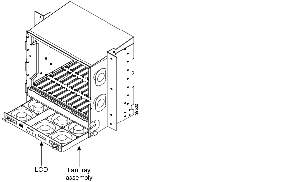
Figure 1-1 shows the location of the fan tray.
Figure 1-1 Installing the Fan-Tray Assembly
Step 4
Stop. You have completed this procedure.
NTP-A119 Install the Alarm Expansion Panel
Note
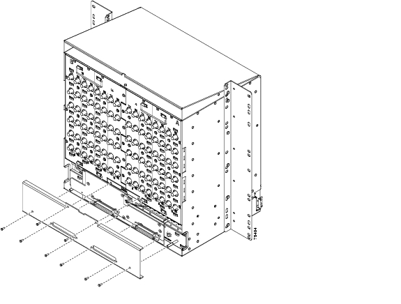
Step 1
Figure 1-2 Replace Backplane Screws with Standoffs
Step 2
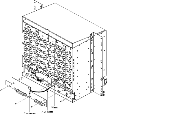
Step 3
Figure 1-3 Installing Standoffs and the AEP
Step 4
Step 5
a.
b.
Figure 1-4 AEP Wire-Wrap Connections to Backplane Pins
Step 6
Stop. You have completed this procedure.
NTP-A8 Attach Wires to Alarm, Timing, LAN, and Craft Pin Connections
Warning
Step 1
Step 2
Step 3
Step 4
Caution
Step 5
•
•
•
Stop. You have completed this procedure.
NTP-A120 Install an External Wire-Wrap Panel to the AEP
Step 1
Figure 1-5 Installing the AEP Cover
Step 2
Step 3
Table 1-3 lists the alarm output pin assignments.
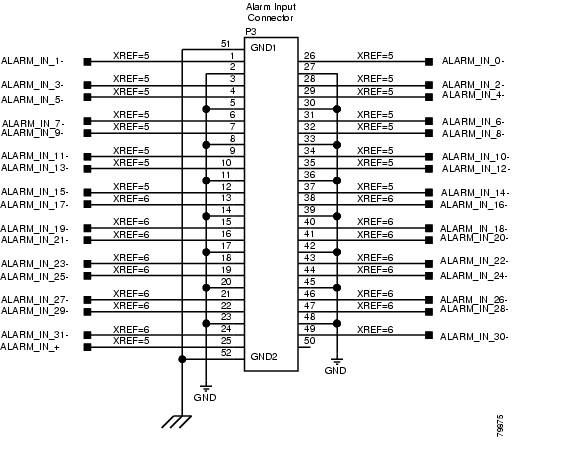
Figure 1-6 illustrates the alarm input connectors.
Figure 1-6 Alarm Input Connector
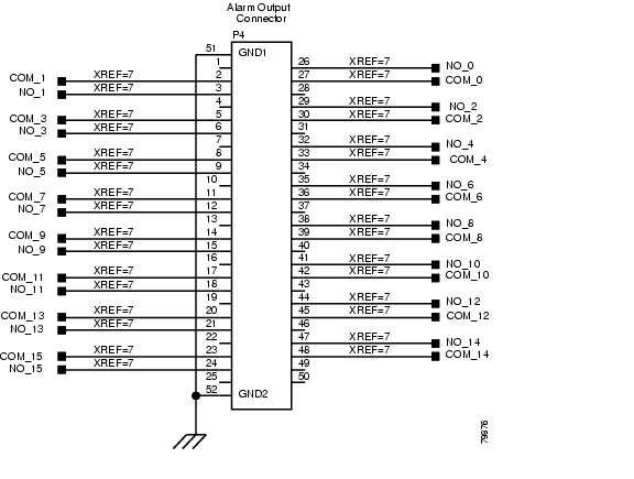
Figure 1-7 illustrates the alarm output connectors.
Figure 1-7 Alarm Output Connector
Step 4
•
•
Stop. You have completed this procedure.
NTP-A9 Install the Electrical Card Cables on the Backplane
Caution
Note
Step 1
Step 2
Step 3
Step 4
Step 5
Step 6
Step 7
Step 8
Step 9
Stop. You have completed this procedure.
NTP-A10 Route Electrical Cables
Step 1
Step 2
Step 3
Stop. You have completed this procedure.
NTP-A11 Install the Rear Cover
Step 1
Step 2
Note
Step 3
Figure 1-8 Mounting Holes on the UBIC-V EIA
Figure 1-9 Mounting Holes on the UBIC-H
Figure 1-10 Mounting Holes on All Other EIA Types
Step 4
Step 5
Figure 1-11 EIA Labelling on the Mounting Bar
Step 6
Step 7
Step 8
Figure 1-12 Installing the Rear Cover Onto the Mounting Bars
Figure 1-13 Installing the Rear Cover with Standoffs
Stop. You have completed this procedure.
NTP-A12 Install Ferrites
Purpose
This procedure describes how to attach ferrites.
Tools/Equipment
Oval and block ferrites
Prerequisite Procedures
A6 Install the Power and Ground
A8 Attach Wires to Alarm, Timing, LAN, and Craft Pin Connections
Required/As Needed
Required
Onsite/Remote
Onsite
Security Level
None
Step 1
Step 2
Step 3
Stop. You have completed this procedure.
NTP-A13 Perform the Shelf Installation Acceptance Test
Warning
Step 1
Table 1-5 Shelf Installation Task Summary
A8 Attach Wires to Alarm, Timing, LAN, and Craft Pin Connections
Step 2
Step 3
Step 4
Stop. You have completed this procedure.
![]()
![]()
![]()
![]()
![]()
![]()
![]()
![]()
Posted: Mon Oct 29 05:57:29 PDT 2007
All contents are Copyright © 1992--2007 Cisco Systems, Inc. All rights reserved.
Important Notices and Privacy Statement.