|
|

Table Of Contents
Configuring Ethernet over MPLS
EoMPLS Configuration Guidelines
VC Type 4 Configuration on PE-CLE Port
VC Type 5 Configuration on PE-CLE Port
EoMPLS Configuration on PE-CLE SPR Interface
EoMPLS Configuration on PE-CLE POS Interface
Bridge Group Configuration on MPLS Cloud-facing Port and SPR Interface
Bridge Group Configuration on MPLS Cloud-facing Port and POS Interface
Setting the Priority of Packets with the EXP
Monitoring and Verifying EoMPLS
Configuring an ML-Series Card for Tunnels Support
Configuring an Interface to Support RSVP-Based Tunnel Signalling and IGP Flooding
Configuring OSPF and Refresh Reduction for MPLS-TE
Monitoring and Verifying MPLS-TE and IP RSVP
Configuring Ethernet over MPLS
This chapter describes how to configure Ethernet over Multiprotocol Label Switching (EoMPLS) on the ML-Series card.
This chapter includes the following major sections:
•
EoMPLS Configuration Example
•
•
•
Understanding EoMPLS
EoMPLS provides a tunneling mechanism for transporting Layer 2 Ethernet frames through an MPLS-enabled Layer 3 core network. It encapsulates Ethernet protocol data units (PDUs) inside MPLS packets and using label stacking forwards them across the MPLS network. EoMPLS is an Internet Engineering Task Force (IETF) standard-track protocol based on the Martini draft, specifically the draft-martini-l2circuit-encap-mpls-01 and draft-martini-l2circuit-transport-mpls-05 sections.
EoMPLS allows service providers to offer customers a virtual Ethernet line service or VLAN service using the service provider's existing MPLS backbone. It also simplifies service provider provisioning, since the provider edge customer-leading edge (PE-CLE) equipment only needs to provide Layer 2 connectivity to the connected customer edge (CE) equipment.
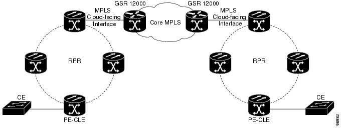
Figure 18-1 shows an example of EoMPLS implemented on a service provider network. In the example, the ML-Series card acts as PE-CLE equipment connecting to the Cisco GSR 12000 Series through an RPR access ring. Point-to-point service is provided to CE equipment in different sites that connect through ML-Series cards to the ML-Series card RPR access ring.
Figure 18-1 EoMPLS Service Provider Network
Although Figure 18-1 shows RPR connecting the ML-Series cards on either side of the core MPLS, the ML-Series cards can also connect through POS ports that are not configured in RPR. In the non-RPR scenario, the ML-Series cards connect in a point-to-point configuration.
Implementing EoMPLS across a service provider's network requires setting up directed Label Distribution Protocol (LDP) sessions (LSPs) between the ingress and egress PE-CLE ML-Series cards to exchange information for a virtual circuit (VC). Each VC consists of two LSPs, one in each direction, since an LSP is a directed path to carry Layer 2 frames in one direction only.
EoMPLS uses a two-level label stack to transport Layer 2 frames, where the bottom/inner label is the VC label and the top/outer label is the tunnel label. The VC label is provided to the ingress PE-CLE by the egress PE-CLE of a particular LSP to direct traffic to a particular egress interface on the egress PE-CLE. A VC label is assigned by the egress PE-CLE during the VC setup and represents the binding between the egress interface and a unique and configurative VC ID. During a VC setup, the ingress and egress PE-CLE exchange VC label bindings for the specified VC ID.
An EoMPLS VC on the ML-Series card is one of two types, based on whether it transports an Ethernet port or an IEEE 802.1Q VLAN over the MPLS core. A VC type 5 tunnels an Ethernet port, and a VC type 4 transports a VLAN. In a VC type 5 session, the user can expect any traffic that is received on an ML-Series card PE-CLE port with an mpls l2transport route command to be tunneled to the remote egress interface on the far-end ML-Series card PE-CLE port. With a VC type 4, a user can expect the tunnel to act as an extension to that VLAN. The EoMPLS session commands are entered on a VLAN subinterface on the PE-CLE, and only VLAN-tagged traffic received on that port will be tunneled to the remote PE-CLE.
EoMPLS Support
EoMPLS on the ML-Series card has the following characteristics:
•
–
–
–
–
•
•
•
•
•
EoMPLS Restrictions
EoMPLS on the ML-Series card has the following restrictions:
•
•
•
•
•
•
Caution
Caution
EoMPLS Quality of Service
The EXP is a 3-bit field and part of the MPLS header. It was created by the IETF on an experimental basis, but later became part of the standard MPLS header. The EXP bits in the MPLS header carry the packet priority. Each label switch router along the path honors the packet priority by queuing the packet into the proper queue and servicing the packet accordingly.
By default, the ML-Series card does not map the IEEE 802.1P bits in the VLAN tag header to the MPLS EXP bits. The MPLS EXP bits are set to a value of 0.
There is no straight copy between Layer 2 CoS and MPLS EXP, but the user can use the set mpls experimental action to set the MPLS EXP bit values based on a match to 802.1p bits. This mapping occurs at the entry point, the ingress of the network.
Quality of service (QoS) for EoMPLS traffic on ML-Series cards uses strict priority and/or weighted round robin scheduling in the egress interface of both imposition and disposition router. This requires selection of the service class queue that determines the type of scheduling. In the imposition router, the priority bits EXP or RPR CoS that are marked based on policing are used to select the service class queue and in the disposition router, the dot1p CoS bits (which are copied from EXP bits of the labels) are used to do the same. In addition to scheduling in the egress interface, the output policy action can also include remarking of EXP and RPR CoS bits.
EoMPLS on the ML-Series card uses the Cisco Modular Quality of Service Command-Line Interface (MQC), just like the standard QoS on the ML-Series card. But the full range of MQC commands are not available. Table 18-1 lists the applicable MQC statements and actions for the ML-Series card interfaces.
Configuring EoMPLS
Implementing EoMPLS on a service provider network requires ML-Series card interfaces to play three major roles. Figure 18-2 illustrates EoMPLS on ML-Series cards and the interfaces that play these major roles.
Figure 18-2 EoMPLS Configuration Example
•
The PE-CLE interface is either a VC type 4 or VC type 5. A VC type 4, which transport IEEE 802.1Q VLAN packets between two PE-CLE ML-Series cards, is configured on a subinterface, such as interface GigE 0.1 on card A and card C in Figure 18-2. A VC type 5, which transports the configured port's packets between two PE-CLE ML-Series cards, is configured on the main Fast Ethernet or Gigabit Ethernet interface. Interface GigE 1 on card A and card C plays the VC type 5 role in Figure 18-2.
For more information on the role of a VC type 4, see the "Understanding EoMPLS" section. For more information on the role of a VC type 5, see the "Understanding EoMPLS" section.
•
A POS interface is used in this role if the ML-Series cards on one side of the MPLS cloud use a point-to-point connection through POS interfaces instead of an RPR to connect. You provision the POS interface, instead of an SPR interface, to bridge the PE-CLE interface on the ML-Series card.
•
A POS interface is used in the SPR interface role if the ML-Series cards on one side of the MPLS cloud use a point-to-point connection through POS interfaces instead of an RPR to connect. You provision the POS interface, instead of the SPR interface, as a member of the bridge group with MPLS cloud-facing interface on the ML-Series card.
Peer ML-Series card interface roles must be configured on both sides of the EoMPLS point-to-point service crossing the MPLS core.
EoMPLS Configuration Guidelines
The ML-Series peer cards on both endpoints of the EoMPLS point-to-point service must be configured. Perform the following configuration tasks to enable EoMPLS:
•
•
•
•
•
•
•
These are the guidelines for configuring EoMPLS:
•
•
•
•
VC Type 4 Configuration on PE-CLE Port
To provision a VC type 4, perform the following procedure on the CE facing port, beginning in global configuration mode:
VC Type 5 Configuration on PE-CLE Port
To provision a VC type 5, perform the following procedure on the customer facing port, beginning in global configuration mode:
EoMPLS Configuration on PE-CLE SPR Interface
To provision the SPR interface for MPLS, perform the following procedure, beginning in global configuration mode:
EoMPLS Configuration on PE-CLE POS Interface
You can also configure a POS interface on the same ML-Series card that hosts the EoMPLS PE-CLE Fast Ethernet or Gigabit Ethernet interfaces. To provision the POS interface for MPLS, perform the following procedure, beginning in global configuration mode:
Bridge Group Configuration on MPLS Cloud-facing Port and SPR Interface
To provision the MPLS cloud-facing port for EoMPLS, perform the following procedure, beginning in global configuration mode:
Bridge Group Configuration on MPLS Cloud-facing Port and POS Interface
To provision the MPLS cloud-facing port for EoMPLS, perform the following procedure, beginning in global configuration mode:
Setting the Priority of Packets with the EXP
EoMPLS can provide QoS using the three EXP bits in a label to determine the priority of packets. Set the experimental bits in both the VC and tunnel labels to support QoS between ML-Series card endpoints.
Note
To set the experimental bits, perform the following procedure, beginning in global configuration mode:
EoMPLS Configuration Example
Figure 18-2 illustrates the sample network that the configuration commands reference. Examples 18-1, 18-2, 18-3, and 18-4 list relevant portions of the configuration files for enabling EoMPLS on ML-Series cards in a sample network.
Example 18-1 ML-Series Card A Configuration
microcode mplsip subnet-zerono ip domain-lookup!mpls label protocol ldp!interface Loopback0ip address 10.10.10.10 255.255.255.255!interface SPR1ip address 100.100.100.100 255.255.255.0no keepalivespr station-id 1mpls iphold-queue 150 in!interface GigabitEthernet0no ip address!interface GigabitEthernet0.1encapsulation dot1Q 10mpls l2transport route 3.3.3.3 1!interface GigabitEthernet1no ip addressmpls l2transport route 4.4.4.4 2!interface POS0no ip addressspr-intf-id 1crc 32!interface POS1no ip addressspr-intf-id 1crc 32router ospf 1log-adjacency-changesnetwork 1.1.1.0 0.0.0.255 area 0network 10.10.10.0 0.0.0.255 area 0!ip classlessno ip http serverExample 18-2 ML-Series Card B Configuration
bridge 10 protocol ieee!!interface SPR1no ip addressno keepalivebridge-group 10hold-queue 150 in!interface GigabitEthernet0no ip addressbridge-group 10Example 18-3 ML-Series Card C Configuration
microcode mplsip subnet-zerono ip domain-lookup!mpls label protocol ldp!interface Loopback0ip address 20.20.20.20 255.255.255.255!interface SPR1ip address 100.100.100.100 255.255.255.0no keepalivespr station-id 4mpls iphold-queue 150 in!interface GigabitEthernet0no ip address!interface GigabitEthernet0.1encapsulation dot1Q 10mpls l2transport route 1.1.1.1 1!interface GigabitEthernet1no ip addressmpls l2transport route 2.2.2.2 2!interface POS0no ip addressspr-intf-id 1crc 32!interface POS1no ip addressspr-intf-id 1crc 32!router ospf 1log-adjacency-changesnetwork 1.1.1.0 0.0.0.255 area 0network 10.10.10.0 0.0.0.255 area 0!ip classlessno ip http serverExample 18-4 ML-Series Card D Configuration
bridge 20 protocol ieee!!interface SPR1no ip addressno keepalivebridge-group 20hold-queue 150 in!interface GigabitEthernet0no ip addressbridge-group 20Monitoring and Verifying EoMPLS
Table 18-2 shows the privileged EXEC commands for monitoring and verifying EoMPLS.
Understanding MPLS-TE
MPLS traffic is normally routed to the least cost path as calculated by OSPF or another IGP routing protocol. This routing gives little or no consideration to varying bandwidth demands or link loads. MPLS traffic engineering (MPLS-TE) overcomes this by mapping traffic flows to paths that take bandwidth demands into account. These paths are known as MPLS-TE tunnels, and they may deviate from the normal IGP calculated routes.
MPLS-TE (RFC 2702) allow service providers to create traffic engineered tunnels to reserve bandwidth for specific types of traffic and to provide point-to-point services for end customers. The ML-Series card supports a maximum of 24 MPLS-TE tunnels. MPLS-TE tunnels can carry a VC type 5, which tunnels an Ethernet port, or a VC type 4, which tunnels an 802.1Q VLAN.
For the ML-Series card to use MPLS-TE, you need to configure three main components. First, you must implement an IGP routing protocol that conveys and distributes information about the link resources throughout the MPLS network. For this purpose, the ML-Series card supports OSPF and OSPF-TE extensions (RFC 2328 and RFC 2370). MPLS-TE extensions for other routing protocols, such as IS-IS, are not supported on the ML-Series card.
Second, you need to configure a signalling protocol to reserve needed resources and establish LSPs across the MPLS network. MPLS-TE tunnels use Resource Reservation Protocol (RSVP) messages (RFC 2205 and RFC 3209) to accomplish this. The ML-Series card supports RSVP and the RSVP extensions for LSP tunnels on both POS interfaces and RPR (SPR) interfaces.
For the third component, you need to set up an MPLS-TE tunnel on the appropriate ML-Series card interface. This requires creating an MPLS tunnel interface with an IP address, destination, encapsulation, bandwidth, and explicit or dynamic path.
RSVP on the ML-Series Card
The ML-Series card uses RSVP to establish MPLS-TE tunnels and the associated tunnel labels. Targeted LDP is still used to establish the VC Labels. Also, RSVP is only used to guarantee the bandwidth on the intermediate nodes on the tunnel. On the ML-Series card, which will be the end-point of the MPLS-TE tunnel, RSVP is used only for bandwidth allocation.
You configure bandwidth guarantees on the ML-Series card ports using the Cisco Modular Quality of Service Command-Line Interface (MQC), just like the standard QoS on the ML-Series card. For more information, see the "EoMPLS Quality of Service" section.
The ML-Series card does not use RSVP messages to carry the information for EoMPLS VCs. LDP sessions are still used to exchange VC information. Also RSVP does not guarantee bandwidth. It only allocates bandwidth.
The ML-Series card supports RSVP summary refresh and RSVP refresh reduction (RFC 2961). Refresh reduction is a set of extensions that reduce the messaging load imposed by RSVP. This helps RSVP scale to support larger numbers of flows. The global configuration command ip rsvp signalling refresh reduction enables this feature.
Ethernet FCS Preservation
You can configure the ML-Series card to encapsulate and preserve the customer's Ethernet FCS. The ML-Series card will carry the Ethernet FCS end-to-end and unmodified across EoMPLS or EoMPLS-TE tunnels. This end-to-end preservation of the original Ethernet FCS is useful for troubleshooting.
Ethernet FCS preservation is off by default on the ML-Series card. Configure Ethernet FCS preservation at the interface or sub-interface configuration level with the [no] fcs-preservation-on command. To operate correctly, both ends of the EoMPLS tunnel need to be configured for FCS preservation.
Configuring MPLS-TE
Perform the following tasks on the MPLS network before you enable MPLS-TE on the ML-Series card :
•
•
To configure MPLS-TE on the ML-Series card, perform the tasks described in the following sections:
•
•
•
•
Note
Note
Configuring an ML-Series Card for Tunnels Support
To configure an ML-Series card to support tunnels, use the following commands in global configuration mode:
Step 1
Router(config)# mpls traffic-eng tunnelsEnables the MPLS-TE tunnel feature on a device.
Configuring an Interface to Support RSVP-Based Tunnel Signalling and IGP Flooding
To configure an interface to support RSVP-based tunnel signalling and IGP flooding, use the following commands in interface configuration mode:
Note
Note
Configuring OSPF and Refresh Reduction for MPLS-TE
For a description of the OSPF commands (excluding the OSPF traffic engineering commands), see the Cisco IOS IP Command Reference, Volume 2 of 3: Routing Protocols
To configure OSPF and Refresh Reduction for MPLS-TE, use the following commands beginning in global configuration mode .
Configuring an MPLS-TE Tunnel
To configure an MPLS-TE tunnel, use the following commands, beginning in global configuration mode:
MPLS-TE Configuration Example
Figure 18-3 illustrates the sample network that the configuration commands reference. Example 18-5 lists relevant portions of the configuration files for enabling MPLS-TE on ML-Series card A in the sample network. ML-Series card A is configured with an explicit path.
Figure 18-3 MPLS-TE Configuration Example
Example 18-5 ML-Series Card A Configuration
microcode mplsip subnet-zerono ip domain-lookup!mpls label protocol ldpmpls traffic-eng tunnelsno mpls traffic-eng auto-bw timers frequency 0!!!interface Loopback0ip address 222.222.222.222 255.255.255.255!interface Tunnel0ip unnumbered Loopback0tunnel destination 212.212.212.212tunnel mode mpls traffic-engtunnel mpls traffic-eng autoroute announcetunnel mpls traffic-eng path-option 1 explicit identifier 1!interface Tunnel1ip unnumbered Loopback0tunnel destination 212.212.212.212tunnel mode mpls traffic-engtunnel mpls traffic-eng autoroute announcetunnel mpls traffic-eng path-option 2 explicit identifier 2!interface GigabitEthernet0no ip addressshutdown!interface GigabitEthernet1no ip address!interface GigabitEthernet1.1encapsulation dot1Q 10fcs-preservation-onmpls l2transport route 212.212.212.212 222!interface GigabitEthernet1.2encapsulation dot1Q 20mpls l2transport route 212.212.212.212 223!interface GigabitEthernet1.3encapsulation dot1Q 30mpls l2transport route 212.212.212.212 224!interface POS0ip address 170.170.170.172 255.255.255.0mpls traffic-eng tunnelstag-switching ipip rsvp bandwidth 10000!interface POS1ip address 2.1.1.22 255.255.255.0mpls traffic-eng tunnelstag-switching ipip rsvp bandwidth 10000!router ospf 1mpls traffic-eng router-id Loopback0mpls traffic-eng area 0log-adjacency-changesnetwork 2.1.1.22 0.0.0.0 area 0network 170.170.170.172 0.0.0.0 area 0network 222.222.222.222 0.0.0.0 area 0!ip classlessno ip http server!!ip explicit-path identifier 1 enablenext-address 2.1.1.1next-address 192.168.3.2next-address 192.168.3.1next-address 2.2.1.1next-address 2.2.1.2next-address 212.212.212.212!ip explicit-path identifier 2 enablenext-address 170.170.170.171next-address 192.168.3.2next-address 192.168.3.1next-address 2.2.1.1next-address 2.2.1.2next-address 212.212.212.212!!!!control-plane!!line con 0exec-timeout 0 0line vty 0 4exec-timeout 0 0password xxxno loginMonitoring and Verifying MPLS-TE and IP RSVP
Table 18-2 shows the privileged EXEC commands supported to monitor and verify the state of MPLS-TE tunnels on the ML-Series cards.
Table 18-2 shows the privileged EXEC commands supported to monitor and verify the state of IP RSVP on the ML-Series cards.
RPRW Alarm
For information on the ONS 15454 RPRW alarm, refer to the online version of the Cisco ONS 15454 Troubleshooting Guide, Release 5.0 at http://www.cisco.com/univercd/cc/td/doc/product/ong/15400/r50docs/r50tblsh/r50alts.htm.
![]()
![]()
![]()
![]()
![]()
![]()
![]()
![]()
Posted: Mon Sep 3 01:08:17 PDT 2007
All contents are Copyright © 1992--2007 Cisco Systems, Inc. All rights reserved.
Important Notices and Privacy Statement.